
US Model
Canadian Model
AEP Model
SERVICE MANUAL
PORTABLE VIDEO PRINTER
SPECIFICATIONS
PVP-MSH
Print method: Variable dot thermal transfer
Print resolution: 254 dpi
Number of printed dots: 640
× 480 (paper feed direction)
Print speed: 3.05 mm (1/8 in.)/second
Size of print pape: 91
× 55 mm (3 5/8 × 2 1/4 in.)
Print area size: 64
× 48 mm (2 5/8 × 1 15/16 in.)
Printing time (approx.): 160 seconds
Number of prints per print cartridge roll: 20
Power consumption: 5 W
Guaranteed operating temperature for printing:
10
°C to 35 °C (50 °F to 95 °F)
Storage temperature: -20
°C to + 55 °C (-4 °F to +131 °F)
Print cartridge storage temperature: -20
°C to + 55 °C (-4 °F to +131 °F)
Dimensions (approx.):
67
× 78 × 97 mm (2 3/5 × 3 1/10 × 3 4/5 in.) (h/w/d)
Mass (approx.): 305 g (10 3/4 oz)
Ver 1.0 2001. 03

-- 2 --
SAFETY-RELATED COMPONENT WARNING!!
COMPONENTS IDENTIFIED BY MARK 0 OR DOTTED LINE WITH
MARK 0 ON THE SCHEMATIC DIAGRAMS AND IN THE PARTS
LIST ARE CRITICAL TO SAFE OPERATION. REPLACE THESE
COMPONENTS WITH SONY PARTS WHOSE PART NUMBERS
APPEAR AS SHOWN IN THIS MANUAL OR IN SUPPLEMENTS
PUBLISHED BY SONY.
ATTENTION AU COMPOSANT AYANT RAPPORT
À LA SÉCURITÉ!
LES COMPOSANTS IDENTIFÉS PAR UNE MARQUE 0 SUR LES
DIAGRAMMES SCHÉMATIQUES ET LA LISTE DES PIÈCES SONT
CRITIQUES POUR LA SÉCURITÉ DE FONCTIONNEMENT. NE
REMPLACER CES COMPOSANTS QUE PAR DES PIÈSES SONY
DONT LES NUMÉROS SONT DONNÉS DANS CE MANUEL OU
DANS LES SUPPÉMENTS PUBLIÉS PAR SONY.
1.
Check the area of your repair for unsoldered or poorly-soldered
connections. Check the entire board surface for solder splashes
and bridges.
2.
Check the interboard wiring to ensure that no wires are
"pinched" or contact high-wattage resistors.
3.
Look for unauthorized replacement parts, particularly
transistors, that were installed during a previous repair. Point
them out to the customer and recommend their replacement.
4.
Look for parts which, through functioning, show obvious signs
of deterioration. Point them out to the customer and
recommend their replacement.
5.
Check the B+ voltage to see it is at the values specified.
6.
Flexible Circuit Board Repairing
· Keep the temperature of the soldering iron around 270°C
during repairing.
· Do not touch the soldering iron on the same conductor of the
circuit board (within 3 times).
· Be careful not to apply force on the conductor when soldering
or unsoldering.
SAFETY CHECK-OUT
After correcting the original service problem, perform the following
safety checks before releasing the set to the customer.
TABLE OF CONTENTS
SERVICE NOTE
1.
POWER SUPPLY DURING REPAIRS ····························· 3
1.
GENERAL
Before You Begin
Identifying the parts and lamp indications ····························· 1-1
Preparation
Inserting the print cartridge ··················································· 1-1
Attaching the printer ······························································ 1-2
Preparing the power supply ··················································· 1-2
Inserting the print paper ························································· 1-3
Making prints - Standard print
Printing images whenever you want to ·································· 1-3
Printing images recorded on "Memory Stick" ······················· 1-4
Printing images with the date ················································ 1-4
Making prints of split screens - Split printing
Printing a single image ·························································· 1-5
Printing images recorded on "Memory Stick" in recording
order ······················································································· 1-5
Printing images with print marks ··········································· 1-5
Additional Information
Precautions ············································································· 1-5
Troubleshooting ····································································· 1-6
Maintenance information ······················································· 1-7
2.
DISASSEMBLY
2-1.
PRINTER UNIT SECTION ············································ 2-1
2-2.
CABINET (UPPER) SECTION ······································ 2-1
2-3.
PRINTER UNIT (PR-036, SW-352 BOARDS) ·············· 2-2
2-4.
CONNECTOR PLUG (HOT SHOE) ······························ 2-3
2-5.
CABINET (LOWER) SECTION ···································· 2-3
2-6.
SHOE ADJUSTER ·························································· 2-4
2-7.
SHOE RETAINER CAM ASSEMBLY ·························· 2-5
3.
BLOCK DIAGRAMS
3-1.
OVERALL BLOCK DIAGRAM ···································· 3-1
4.
PRINTED WIRING BOARDS AND
SCHEMATIC DIAGRAMS
4-1.
FRAME SCHEMATIC DIAGRAM ································ 4-1
4-2.
PRINTED WIRING BOARDS AND
SCHEMATIC DIAGRAMS ············································ 4-4
· SW-352 (PRINT SW)
PRINTED WIRING BOARD AND
SCHEMATIC DIAGRAM ······························ 4-5
· PR-036 (PRINTER CONTROL, SYSTEM CONTROL,
DC/DC CONVERTER)
PRINTED WIRING BOARD ························· 4-7
· PR-036 (PRINTER CONTROL)(1/3)
SCHEMATIC DIAGRAM ······························ 4-9
· PR-036 (SYSTEM CONTROL)(2/3)
SCHEMATIC DIAGRAM ···························· 4-11
· PR-036 (DC/DC CONVERTER)(3/3)
SCHEMATIC DIAGRAM ···························· 4-13
4-3.
WAVEFORMS ······························································ 4-16
4-4.
MOUNTED PARTS LOCATION ································· 4-16
5.
ADJUSTMENTS
1.
ADJUSTMENT ······························································· 5-1
1-1.
PREPARATIONS BEFORE ADJUSTMENTS ·············· 5-1
1-1-1. Equipment to Required ···················································· 5-1
1-1-2. Connecting the Equipment ·············································· 5-1
1-1-3. Confirmation of the Adjustment RV. ······························· 5-1
1-2.
Printer Head Voltage Adjustment
(Without Adjustment RV) (PR-036 board) ······················ 5-2
1-3.
Printer Head Voltage Adjustment
(With Adjustment RV) (SW-352 board) ·························· 5-3
6.
REPAIR PARTS LIST
6-1.
EXPLODED VIEWS ······················································ 6-1
6-1-1. OVERALL SECTION ····················································· 6-1
6-2.
ELECTRICAL PARTS LIST ·········································· 6-2
-- 3 --
SERVICE NOTE
1.
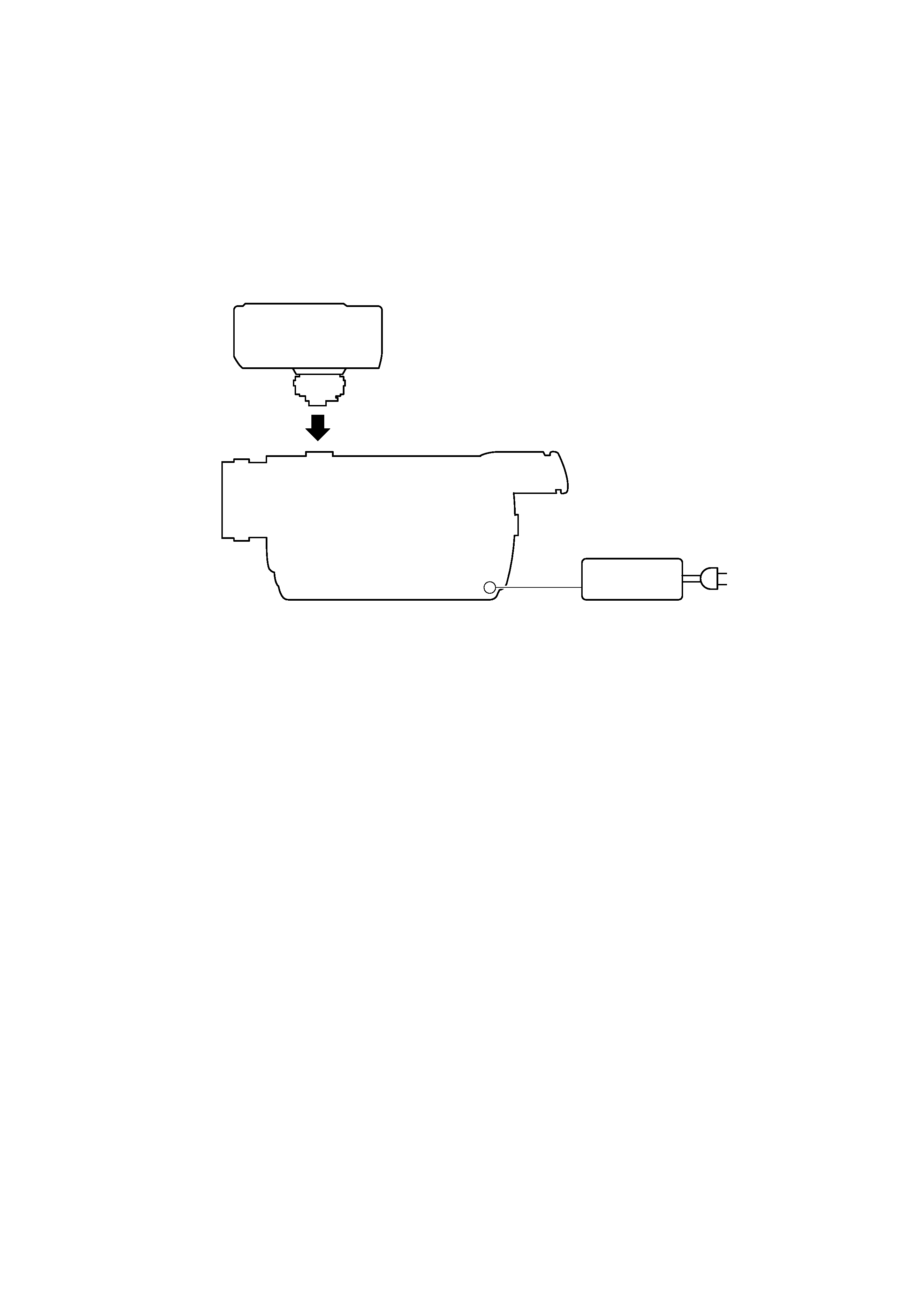
POWER SUPPLY DURING REPAIRS
Connect this printer to the Intelligent accessory shoe (15P) of the camcorder suitable for this printer, and repair/adjust this printer.
Camcorders suitable for this printer are shown in the following.
DCR-TRV830/TRV830E, etc.
Switch setting of the camcorder:
POWER ................................................................. MEMORY
Camcorder
AC IN
Printer
Intelligent accessory shoe (15P)
DC IN jack
AC power adaptor
AC-L10,
AC-VQ800 etc.
1-1
SECTION 1
GENERAL
PVP-MSH
This section is extracted from
instruction manual.
Before
You
Begin
5-US
BBefore You Begin
Identifying the parts and lamp indications
POWER lamp (green)
Lit
· The printer cover is open.
PAPER lamp (red)
Fast flashing
· Print paper error
Slow flashing
· Print paper not inserted
CARTRIDGE lamp (red)
Fast flashing
· Ribbon error
· Run out of ribbon
Slow flashing
· Ribbon not inserted
Print lamp ···· (4)
Print cartridge
lid
PRINT CARTRIDGE
OPEN
Paper feeder
Paper dispenser
Print lamp ··· (3)
Print lamp ·· (2)
Print lamp · (1)
Printer cover
PRINT button
POWER lamp
PAPER lamp
CARTRIDGE lamp
6-US
Print lamp 1 (orange)
Lit
· Cyan is being printed.
Print lamp 2 (orange)
Lit
· Magenta is being printed.
Print lamp 3 (orange)
Lit
· Yellow is being printed.
Print lamp 4 (orange)
Lit
· Overcoat is being printed.
Print lamps 1 and 2 flashing simultaneously
Fast flashing
· Printer internal error
Print lamps 3 and 4 flashing simultaneously
Fast flashing
· The temperature inside the printer has risen.
Identifying the parts and lamp indications (continued)
Preparation
7-US
BPreparation
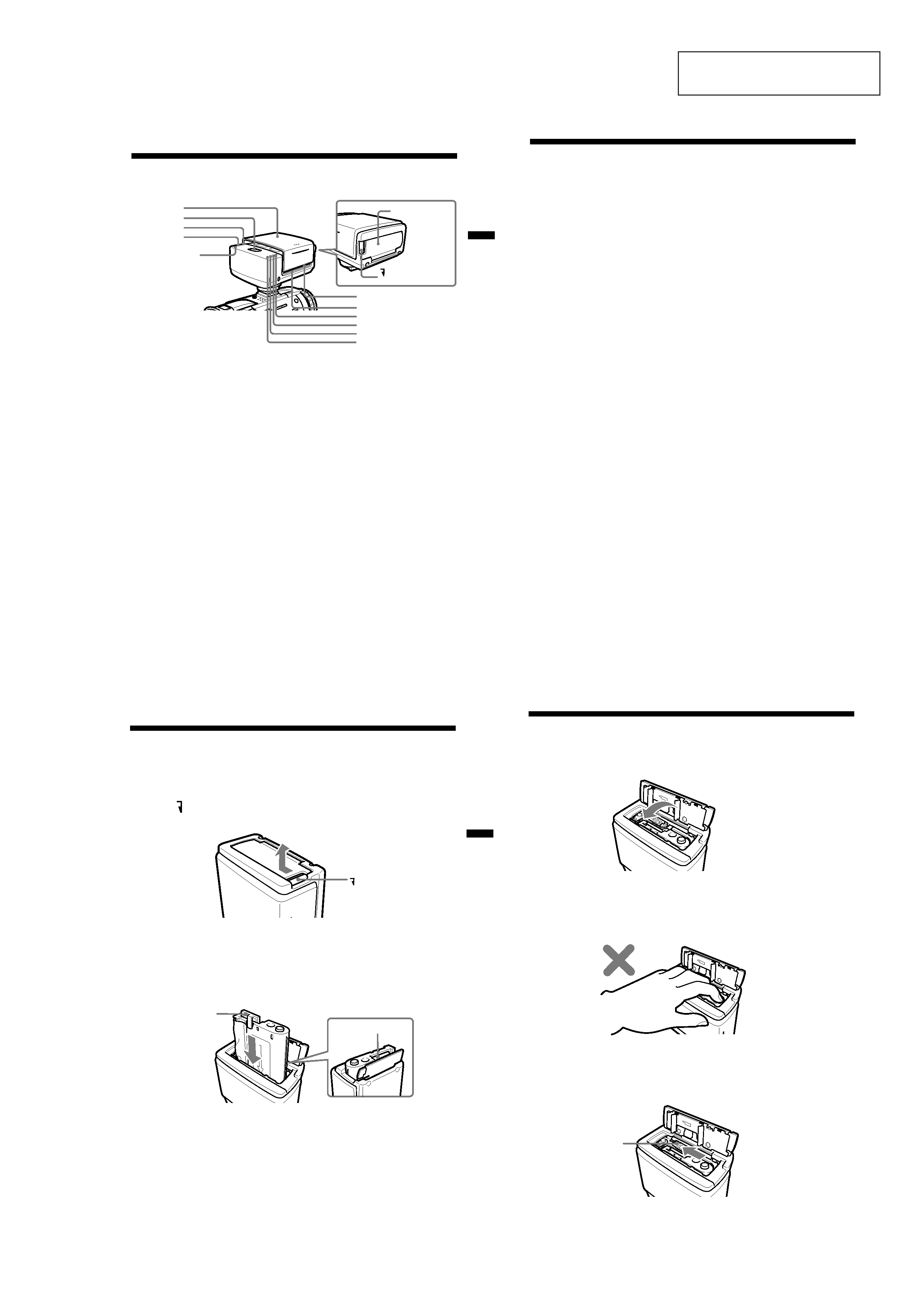
Inserting the print cartridge
Be sure to use the specified print cartridge.
A single new print cartridge allows you to make 20 prints.
1 Slide PRINT CARTRIDGE OPEN knob on the side of this unit in
the direction of the arrow, and open the print cartridge lid.
2 Insert the print cartridge as far as possible in the direction of
the arrow on the cartridge case until it clicks into the cartridge
compartment.
Insert the print cartridge so that the printing head is located between
the ribbon and the cartridge case.
The ribbon protector is located between the ribbon and the cartridge
case. This protector prevents the ribbon from being tangled when
inserting the print cartridge into the cartridge compartment.
Insert the print cartridge as it is into the cartridge compartment
without removing the ribbon protector. When the print cartridge is
inserted, the ribbon protector comes loose. Dispose of the ribbon
protector after the print cartridge is inserted.
PRINT CARTRIDGE
OPEN
Printing head
Ribbon protector
(blue cover)
8-US
Removing the print cartridge
Slide the removal switch to the end in the direction of the arrow, and
remove the print cartridge.
Inserting the print cartridge (continued)
3 Close the print cartridge lid completely.
PNote
The inside of this unit sometimes heats up. Do not put your hand inside the
print cartridge compartment.
Removal switch
1-2
Preparation
9-US
PNotes
· If the print cartridge is not inserted when the power is turned on, the
CARTRIDGE lamp flashes slowly. The CARTRIDGE lamp flashes fast
when an error occurs on the print cartridge or when the ribbon has run
out.
· If the removal switch is not slid to the end, you may not be able to
remove the print cartridge.
When the print cartridge cannot be inserted easily
Remove the print cartridge, and then re-insert it.
Turn in the direction of the arrow to take up ribbon slack only if ribbon
slack prevents the print cartridge from being inserted correctly.
PNotes
· Do not remove the print cartridge when print paper is inserted. This may
cause this unit to malfunction.
· Do not remove the print cartridge until you use it up. If you reinsert the print
cartridge before you use it up, the possible number of prints per print
cartridge roll may be reduced by one.
10-US
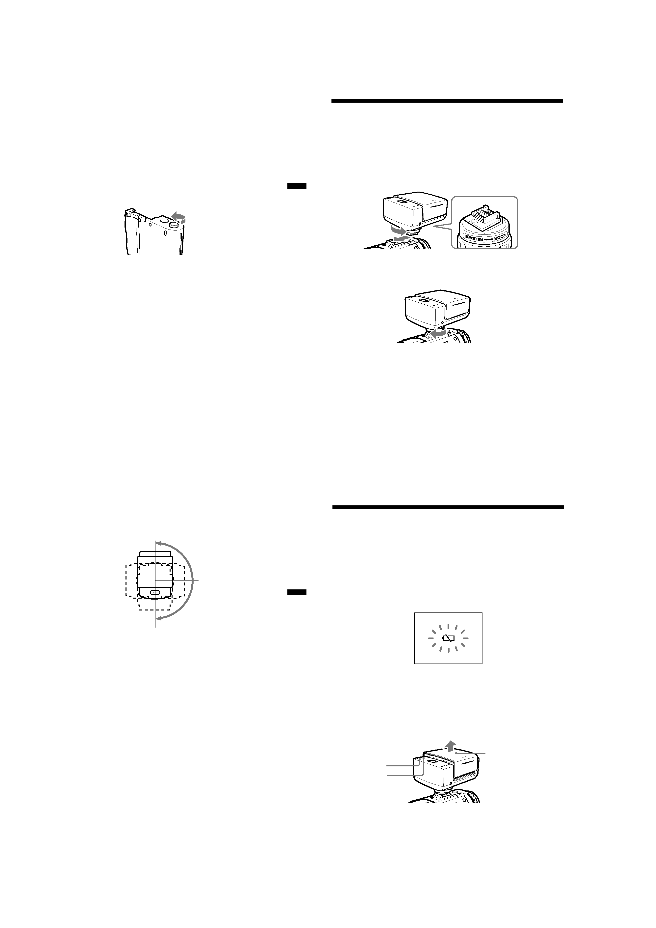
Attaching the printer
Before attaching this unit to your camcorder, make sure that your
camcorder is turned off.
1 Turn the knob in the direction of the arrow (RELEASE) to
loosen. Then, check the direction of the arrow on the shoe
attachment section on this unit, and firmly insert this unit
until it contacts the inside of the accessory shoe.
2 Turn the knob in the direction of the arrow (LOCK), and firmly
tighten until the knob comes to a stop.
PNotes
·If you cannot insert this unit, turn the knob in the direction of the arrow
(RELEASE) to unlock.
·Do not insert this unit backwards. Be sure to insert this unit in the direction of
the arrow.
· Do not lift up your camcorder by this unit.
· Attach this unit to your camcorder firmly. Otherwise, it may become detached
from your camcorder.
Preparation
11-US
PNote
Do not rotate this unit forcibly more than 180º in the clockwise direction. Doing
so may destroy this unit.
To remove the printer
Turn the knob in the direction of the arrow (RELEASE) to loosen, and then
pull out this unit in the direction opposite to the arrow to remove it.
Rotating the printer
This unit rotates toward about 180º in the clockwise direction.
0º
180º
90º
12-US
Preparing the power supply
Be sure to use a fully charged battery, the AC power adaptor or the AC
power adaptor/charger.
Printing is not possible if the battery is low. However, recording may be
possible depending on how much the battery power remains. The
remaining battery time indicator does not indicate the possible printing
time.
If you press PRINT or insert the print paper while the battery is low, the
warning indicator,
E, will be displayed on the LCD screen. Replace with a
fully charged battery.
1 Set the POWER switch on your camcorder to MEMORY.
2 Slide the printer cover in the direction of the arrow to open
while holding your camcorder.
The POWER lamp lights, the sound of motor operation stops, and the
PAPER lamp flashes slowly after several seconds.
PNote
While recording or playback mode, this unit cannot be turned on.
Printer cover
POWER lamp
PAPER lamp