1
MICROFILM
SERVICE MANUAL
Canadian Model
E Model
PMC-D307
PERSONAL COMPONENT SYSTEM
CD player section
System
Compact disc digital audio system
Laser diode properties
Material: GaAlAs
Wave length: 780 nm
Emission duration: Continuous
Laser output: Less than 44.6 µW
(This output is the value measured at a distance of
about 200 mm from the objective lens surface on
the optical pick-up block with 7 mm aperture.)
Spindle speed
200 r/min (rpm) to 500 r/min (rpm) (CLV)
Number of channels
2
Frequency response
20 - 20,000 Hz +1/2.5 dB
Wow and flutter
Below measurable limit
Radio section
Frequency range
FM: 87.6 - 108 MHz
AM: 530 - 1,710 kHz
Aerials
FM: Lead aerial
AM: External aerial terminal
Continued on next page
Cassette-corder section
Recording system
4-track 2 channel stereo
Fast winding time
Approx. 130 s (sec.) with Sony cassette C-60
Frequency response
TYPE I (normal): 40 - 15,000 Hz
General
Speaker
Full range: 8 cm (3 1/4 in.) dia., 6.0 ohms,
cone type
× 2
Input
LINE IN jack (stereo minijack)
Minimum input level 250 mV
Outputs
Headphones jack (stereo minijack)
For 16 - 68 ohms impedance headphones
LINE OUT jack (stereo minijack)
Rated output level 440 mV at load impedance
47 kilohms
Optical digital output (optical output connector)
Wave length: 630 - 690 nm
Power output
10 W + 10 W (at 6.0 ohms, 10% harmonic distortion)
Power requirements
For personal component system:
120 V AC, 60 Hz
For remote commander:
3 V DC, 2 size AA (R6) batteries
CD
Model Name Using Similar Mechanism PMC-D305
Section
CD Mechanism Type
KSM-213CDM
Optical Pick-up Name
KSS-213C
Tape
Model Name Using Similar Mechanism NEW
Section Tape Transport Mechanism Type
MF-D307
SPECIFICATIONS
Ver 1.0 1999. 05

2
Power consumption
AC 35 W
Dimensions (incl. projecting parts)
Player: approx. 130
× 211 × 200 mm (w/h/d)
(5 1/8
× 8 3/8 × 7 7/8 inches)
Left speaker: approx. 130
× 210 × 235 mm
(w/h/d) (5 1/8
× 8 3/8 × 9 3/8 inches)
Right speaker: approx. 130
× 210 × 200 mm
(w/h/d) (5 1/8
× 8 3/8 × 7 7/8 inches)
Mass
Player: approx. 1.7 kg (3 lb. 12 oz.)
Left speaker: approx. 3.2 kg (7 lb. 1 oz.)
Right speaker: approx. 1.6 kg (3 lb. 9 oz.)
Supplied accessories
Remote commander RMT-C305A (1)
AM loop aerial (1)
Audio connecting cord (1)
Slip stoppers (8)
Design and specifications are subject to change without
notice.
TABLE OF CONTENTS
1. SERVICING NOTES ......................................................... 3
2. GENERAL
2-1. Location of Controls ........................................................... 4
3. DISASSEMBLY
3-1. Cabinet (Rear) ..................................................................... 5
3-2. Case (Lower) Section .......................................................... 6
3-3. Tape Mechanism Deck Section ........................................... 6
3-4. Cabinet (CD) Section .......................................................... 7
3-5. CD, Control Board .............................................................. 7
3-6. Optical Pick-up Section ...................................................... 8
3-7. Rear Chassis (Speaker) Section .......................................... 8
3-8. Amplifier, Terminal, Jack Board ......................................... 9
3-9. Power Board ........................................................................ 9
4. MECHANICAL ADJUSTMENTS ............................... 10
5. ELECTRICAL ADJUSTMENTS
Tape Section .......................................................................... 10
Tuner Section ......................................................................... 12
CD Section ............................................................................ 14
6. DIAGRAMS
6-1. IC Pin Description ............................................................. 18
6-2. Circuit Boards Location .................................................... 20
6-3. Block Diagram Tuner Section ....................................... 21
6-4. Block Diagram CD Section ........................................... 23
6-5. Block Diagram Tape Section ........................................ 25
6-6. Printed Wiring Board Tuner Section ............................. 27
6-7. Schematic Diagram Tuner Section ................................ 29
6-8. Printed Wiring Boards CD Section ............................... 31
6-9. Schematic Diagram CD Section .................................... 33
6-10. Printed Wiring Boards Main Section ............................ 36
6-11. Schematic Diagram Main Section ................................. 39
6-12. Printed Wiring Boards Control Section ......................... 42
6-13. Schematic Diagram Control Section ............................. 45
6-14. Printed Wiring Boards Power Amplifier Section .......... 47
6-15. Schematic Diagram Power Amplifier Section .............. 49
7. EXPLODED VIEWS
7-1. Case Section ...................................................................... 55
7-2. Cabinet (Front) Section ..................................................... 56
7-3. Cabinet (CD) Section ........................................................ 57
7-4. Optical Pick-up Section .................................................... 58
7-5. Tape Mechanism Deck Section-1 ...................................... 59
7-6. Tape Mechanism Deck Section-2 ...................................... 60
7-7. Speaker (L) Section ........................................................... 61
7-8. Speaker (R) Section .......................................................... 62
8. ELECTRICAL PARTS LIST ........................................ 63
3
S801
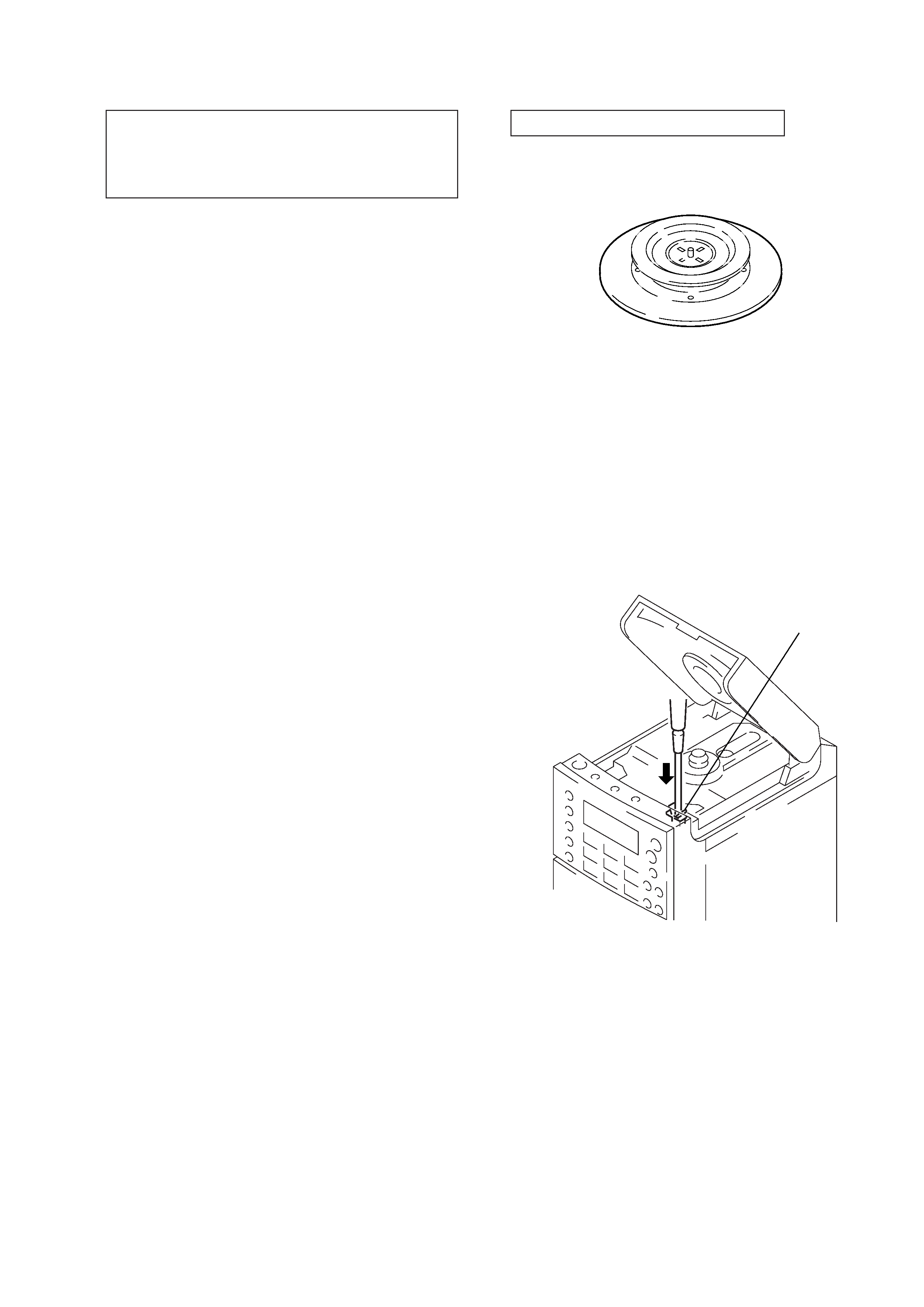
CHUCK PLATE JIG ON REPAIRING
On repairing CD section, playing a disc without the lid (CD), use
Chuck Plate Jig.
· Code number of Chuck Plate Jig: X-4918-255-1
SECTION 1
SERVICING NOTES
LASER DIODE AND FOCUS SEARCH OPERATION
CHECK
1. Turn POWER switch on with to disc inserted and press
FUNCTION button to CD position.
2. Open the lid (CD).
3. Turn on S801 as following figure.
4. Press the
( (CD) button.
5. Confirm the laser diode emission while observing the objecting
lens. When there is no emission, Auto Power Control circuit or
Optical Pick-up is broken.
Objective lens moves up and down three times for focus search.
HOW TO CHANGE THE FM CERAMIC FILTERS
This model is used three ceramic filters of CF1, 2 and CF3.
Therefore, the ceramic filters must change three pieces together since
it's supply three pieces in one package as a spare parts.
SAFETY-RELATED COMPONENT WARNING!!
COMPONENTS IDENTIFIED BY MARK
! OR DOTTED LINE
WITH MARK
! ON THE SCHEMATIC DIAGRAMS AND IN
THE PARTS LIST ARE CRITICAL TO SAFE OPERATION.
REPLACE THESE COMPONENTS WITH SONY PARTS WHOSE
PART NUMBERS APPEAR AS SHOWN IN THIS MANUAL OR
IN SUPPLEMENTS PUBLISHED BY SONY.
CAUTION
Use of controls or adjustments or performance of proce-
dures other than those specified herein may result in haz-
ardous radiation exposure.
Flexible Circuit Board Repairing
· Keep the temperature of the soldering iron around 270°C during
repairing.
· Do not touch the soldering iron on the same conductor of the
circuit board (within 3 times).
· Be careful not to apply force on the conductor when soldering
or unsoldering.
Notes on Chip Component Replacement
· Never reuse a disconnected chip component.
· Notice that the minus side of a tantalum capacitor may be dam-
aged by heat.
NOTES ON HANDLING THE OPTICAL PICK-UP BLOCK
OR BASE UNIT
The laser diode in the optical pick-up block may suffer electrostatic
breakdown because of the potential difference generated by the
charged electrostatic load, etc. on clothing and the human body.
During repair, pay attention to electrostatic breakdown and also use
the procedure in the printed matter which is included in the repair
parts.
The flexible board is easily damaged and should be handled with
care.
NOTES ON LASER DIODE EMISSION CHECK
The laser beam on this model is concentrated so as to be focused on
the disc reflective surface by the objective lens in the optical pick-
up block. Therefore, when checking the laser diode emission,
observe from more than 30 cm away from the objective lens.
ATTENTION AU COMPOSANT AYANT RAPPORT
À LA SÉCURITÉ!!
LES COMPOSANTS IDENTIFIÉS PAR UNE MARQUE
! SUR LES
DIAGRAMMES SCHÉMATIQUES ET LA LISTE DES PIÈCES
SONT CRITIQUES POUR LA SÉCURITÉ DE FONCTIONNEMENT.
NE REMPLACER CES COMPOSANTS QUE PAR DES PIÈCES
SONY DONT LES NUMÉROS SONT DONNÉS DANS CE MANUEL
OU DANS LES SUPPLÉMENTS PUBLIÉS PAR SONY.
4
1
2
3
4
5
6
7
8
9
10
11
12
13
14
15
16
17
18
19
20
21
22
23
24
SECTION 2
GENERAL
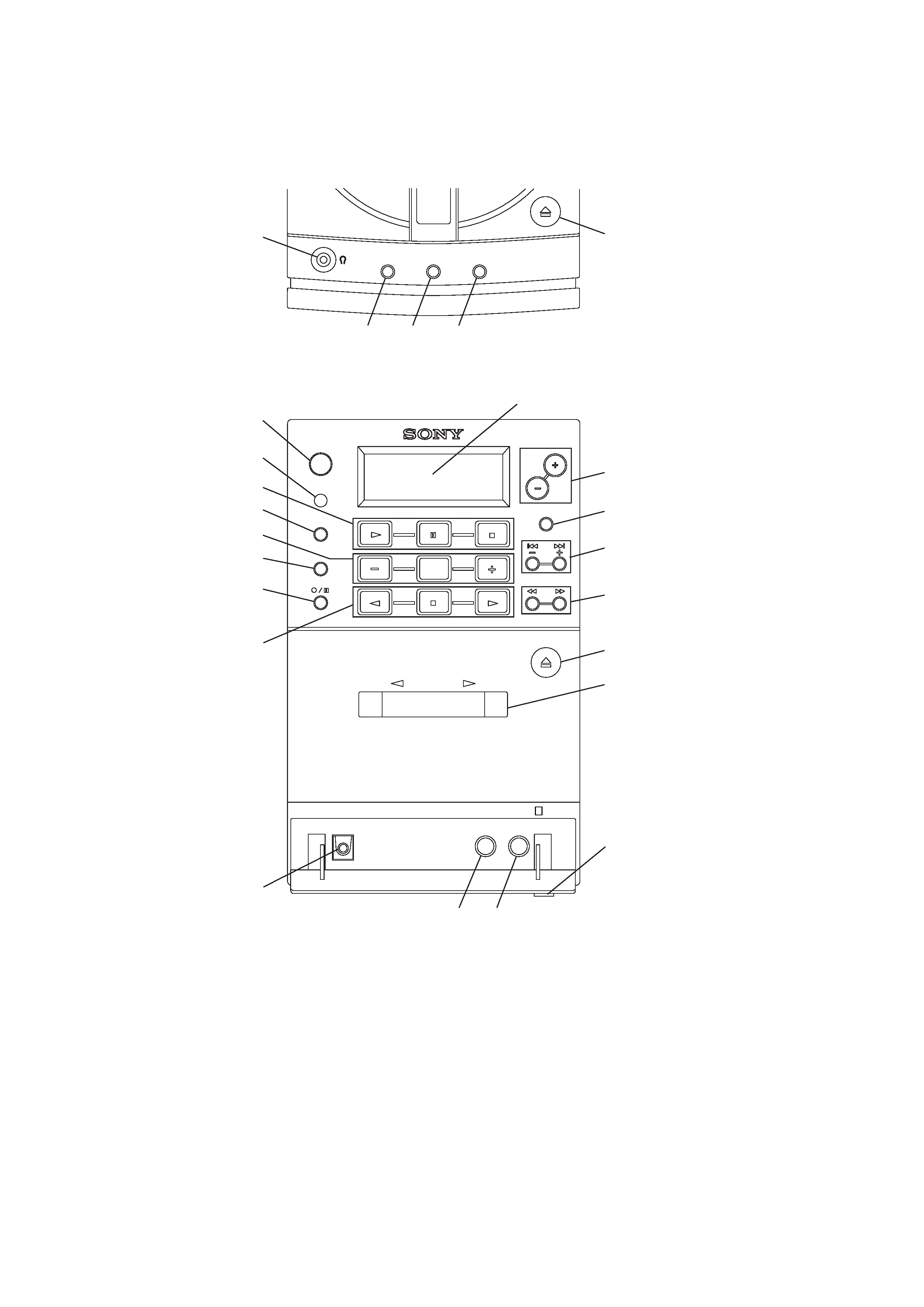
2-1. LOCATION OF CONTROLS
1.
6 OPEN/CLOSE (CD) button
2. PLAY MODE MONO/ST/ISS button
3. PGM SET/AUTO PRESET button
4. SOUND button
5.
2 (Headphones) jack
6. Display window
7. POWER button
8. Remote sensor window
9. CD operation buttons
( (Play) button
P (Pause) button
p (Stop) button
10. FUNCTION button
11. RADIO operation buttons
PRESET button
BAND button
PRESET + button
12. DIR MODE button
13.
r/P (Recording/pause) button
14. TAPE operation buttons
9 (Reverse) button
p (Stop) button
( (Play) button
15. OPTICAL DIGITAL OUT (CD) jack
16. VOLUME +/ button
17. DISPLAY/ENTER button
18.
=/+, TUNE +/ button
19.
0/) button
20.
6 PUSH (cassette holder open) button
21. Cassette holder
22. OPEN
$ knob
23. LINE OUT jack
24. LINE IN jack
upper side view
front side view
5
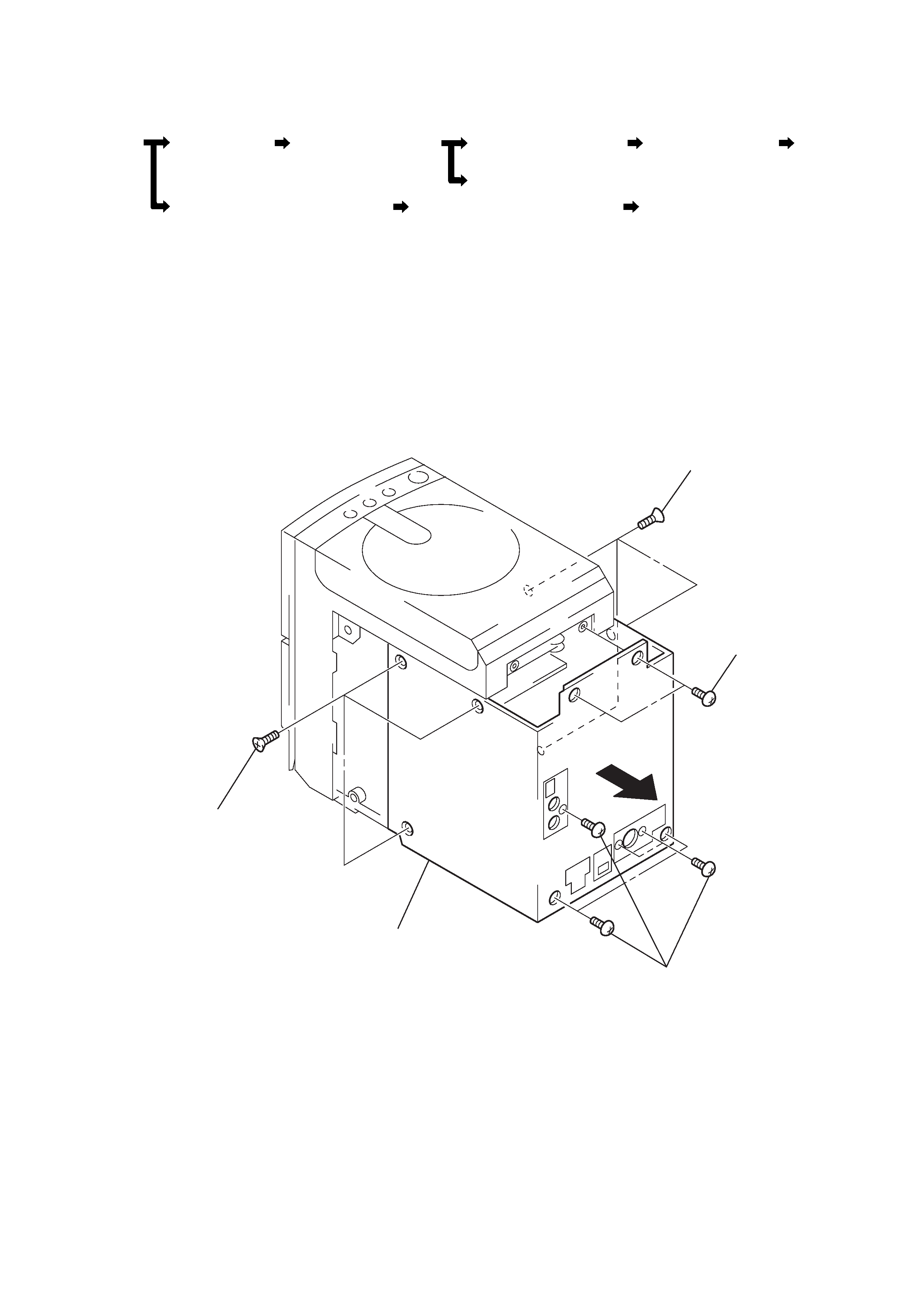
5 cabinet (rear)
4 BVTP 3x10
3 BVTP 3x10
2 KTP 3x10
1 KTP 3x10
Set
Cabinet (rear)
Rear chassis (speaker) section
Amplifier, terminal, jack board
Power board
Case (lower) section
Cabinet (CD) section
Optical
pick-up
section
Tape mechanism deck section
CD, Control board
· The equipment can be removed using the following procedure.
SECTION 3
DISASSEMBLY
3-1. CABINET (REAR)
Note : Follow the disassembly procedure in the numerical order given.