MICROFILM
SERVICE MANUAL
US Model
Canadian Model
AEP Model
UK Model
E Model
Australian Model
Hong Kong Model
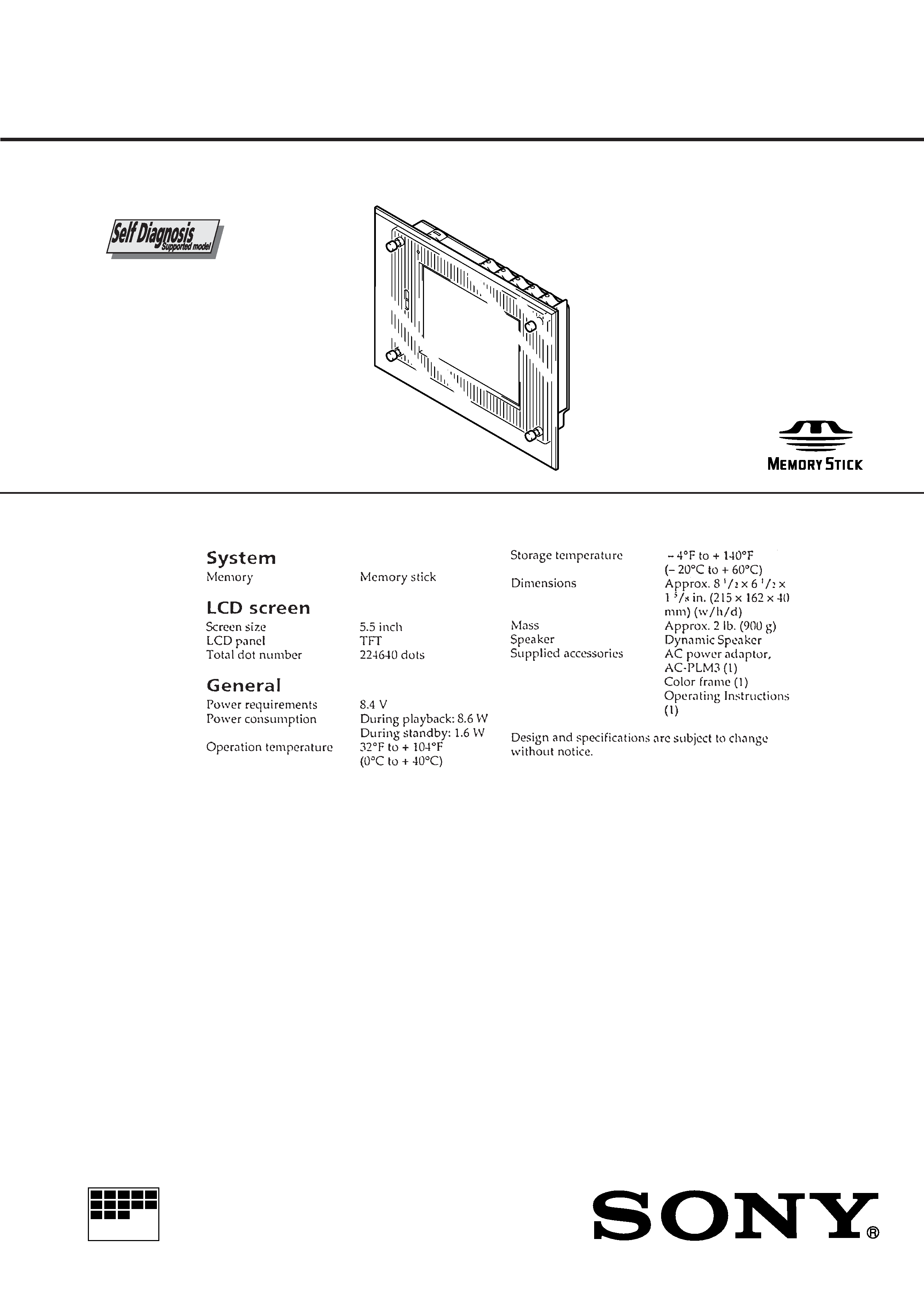
DIGITAL PHOTO FRAME
PHD-A55
SPECIFICATIONS
TM
Ver 1.0 1999. 04
2
1. Check the area of your repair for unsoldered or poorly-sol-
dered connections. Check the entire board surface for solder
splashes and bridges.
2. Check the interboard wiring to ensure that no wires are
"pinched" or contact high-wattage resistors.
3. Look for unauthorized replacement parts, particularly transis-
tors, that were installed during a previous repair. Point them
out to the customer and recommend their replacement.
SAFETY CHECK-OUT
After correcting the original service problem, perform the following
safety checks before releasing the set to the customer.
4. Look for parts which, though functioning, show obvious signs
of deterioration. Point them out to the customer and recom-
mend their replacement.
5. Check the B+ voltage to see it is at the values specified.
6. Flexible Circuit Board Repairing
·
Keep the temperature of the soldering iron around 270 °C
during repairing.
·
Do not touch the soldering iron on the same conductor of
the circuit board (within 3 times).
·
Be careful not to apply force on the conductor when sol-
dering or unsoldering.
ATTENTION AU COMPOSANT AYANT RAPPORT
À LA SÉCURITÉ!
LES COMPOSANTS IDENTIFIÉS PAR UNE MARQUE
!
SUR LES DIAGRAMMES SCHÉMATIQUES ET LA LISTE
DES PIÈCES SONT CRITIQUES POUR LA SÉCURITÉ
DE FONCTIONNEMENT. NE REMPLACER CES COM-
POSANTS QUE PAR DES PIÈCES SONY DONT LES
NUMÉROS SONT DONNÉS DANS CE MANUEL OU
DANS LES SUPPLÉMENTS PUBLIÉS PAR SONY.
SAFETY-RELATED COMPONENT WARNING!!
COMPONENTS IDENTIFIED BY MARK
! OR DOTTED
LINE WITH MARK
! ON THE SCHEMATIC DIAGRAMS
AND IN THE PARTS LIST ARE CRITICAL TO SAFE
OPERATION. REPLACE THESE COMPONENTS WITH
SONY PARTS WHOSE PART NUMBERS APPEAR AS
SHOWN IN THIS MANUAL OR IN SUPPLEMENTS PUB-
LISHED BY SONY.
SERVICE NOTE
· NOTE FOR REPAIR
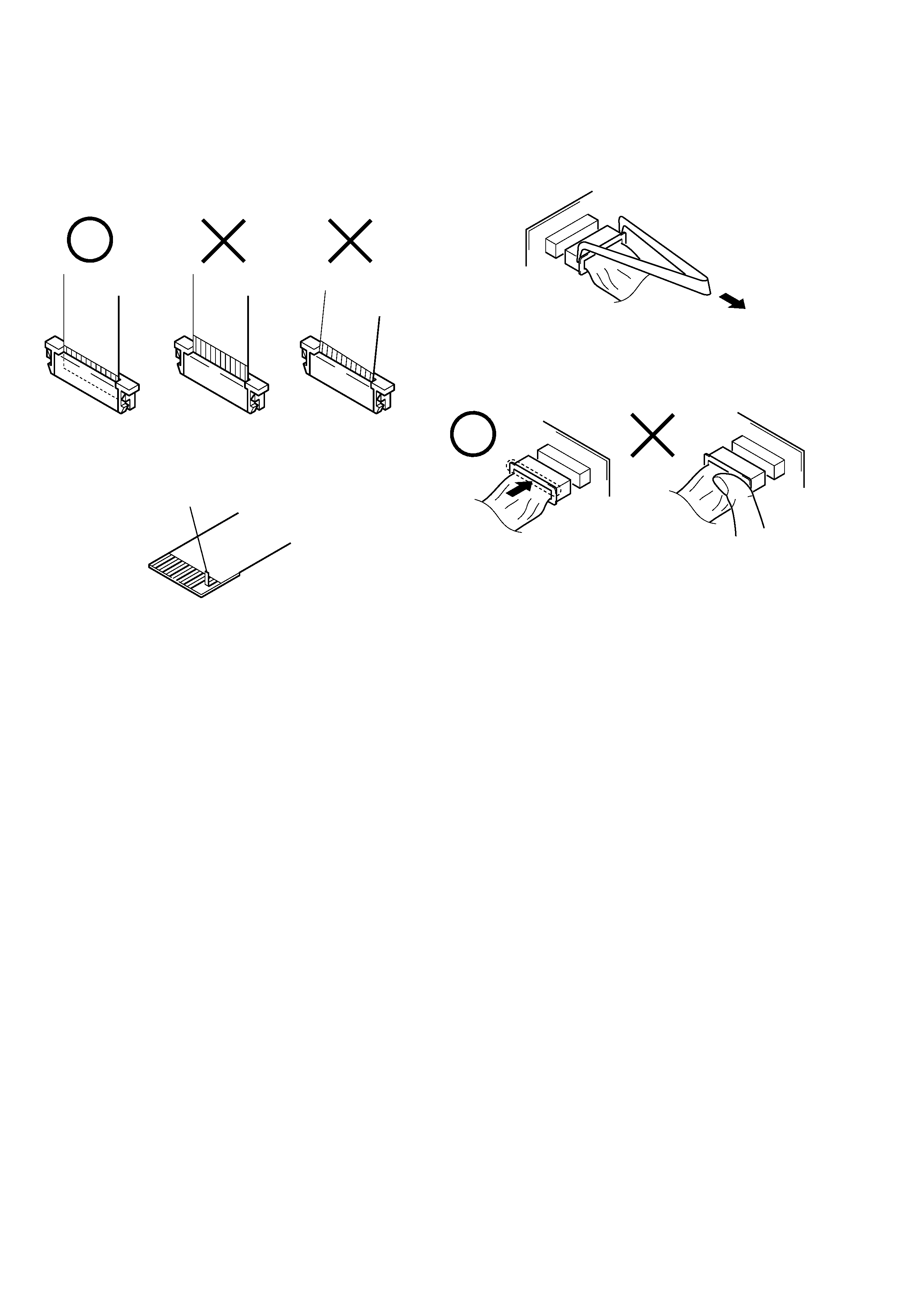
Make sure that the flat cable and flexible board are not cracked of
bent at the terminal.
Do not insert the cable insufficiently nor crookedly.
When remove a connector, don't pull at wire of connector.
Be in danger of the snapping of a wire.
Cut and remove the part of gilt
which comes off at the point.
(Take care that there are some
pieces of gilt left inside)
When installing a connector, don't press down at wire of connector.
Be in danger of the snapping of a wire.

3
SERVICE NOTE ................................................................... 2
1.
GENERAL
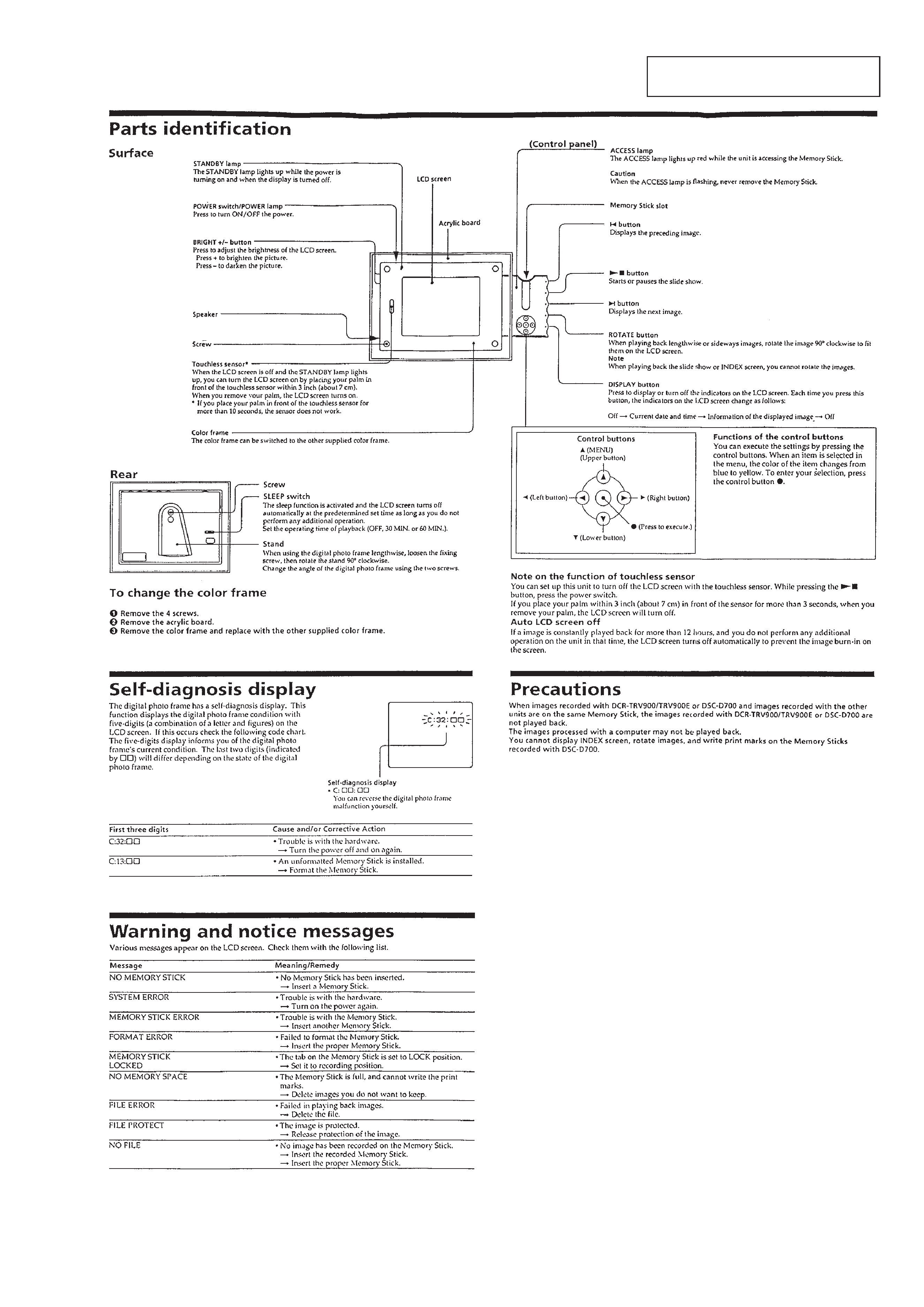
Parts Indentification ................................................................. 1-1
Self-Diagnosis Display ............................................................ 1-1
Warning and notice messages ................................................ 1-1
Precautions .............................................................................. 1-1
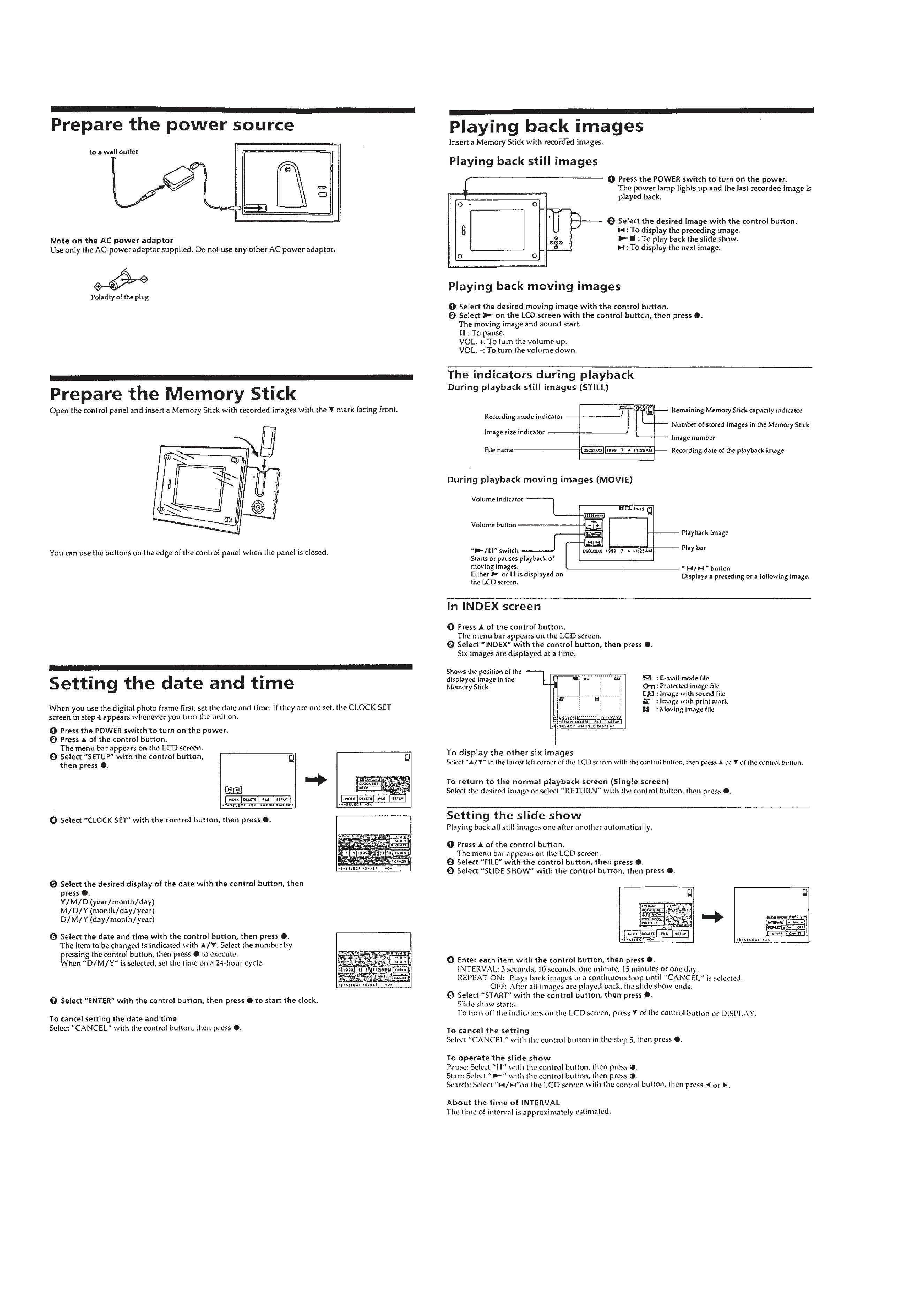
Prepare the Power Source ...................................................... 1-2
Prepare the Memory Stick ....................................................... 1-2
Setting the Date and Time ....................................................... 1-2
Playing Back Images ............................................................... 1-2
Changing the Menu Setting ..................................................... 1-3
Troubleshooting ....................................................................... 1-3
2.
DISASSEMBLY
2-1.
Removal of Front Cabinet Assembly ............................ 2-1
2-2.
Removal of Crystal Indication Module .......................... 2-1
2-3.
Removal of Control Panel Block Assembly .................. 2-1
2-4.
Removal of KY-41 Board ............................................... 2-1
2-5.
Removal of EX-35 Board .............................................. 2-2
2-6.
Removal of FU-136 Board ............................................ 2-2
2-7.
Removal of PS-423 Board ............................................ 2-2
2-8.
Removal of SY-55 Board ............................................... 2-2
2-9.
Circuit Boards Location ................................................. 2-3
3.
BLOCK DIAGRAMS
3-1.
Overall Block Diagram ................................................... 3-1
3-2.
Memory Stick Interface Block Diagram ......................... 3-3
3-3.
Audio, LCD Drive Block Diagram .................................. 3-5
3-4.
Mode Control Block Diagram ........................................ 3-7
3-5.
Power Block Diagram .................................................... 3-9
4.
PRINTED WIRING BOARDS AND
SCHEMATIC DIAGRAMS
4-1.
Frame Schematic Diagram ............................................ 4-1
4-2.
Printed Wiring Boards and Schematic Diagrams ......... 4-4
·
SY-55 Printed Wiring Board ..................................... 4-5
·
SY-55 (MEMORY READER) Schematic Diagram ... 4-10
·
SY-55 (SYSTEM CONTROL) Schematic Diagram .. 4-13
·
SY-55 (VIDEO DECODER) Schematic Diagram ..... 4-16
·
SY-55 (LCD DRIVER) Schematic Diagram ............. 4-19
·
SY-55 (AUDIO DECODER) Schematic Diagram ..... 4-23
·
SY-55 (SPEAKER AMP) Schematic Diagram ......... 4-25
·
SY-55 (MODE CONTROL) Schematic Diagram ...... 4-28
·
SY-55 (DC/DC CONVERTER)
Schematic Diagram .................................................. 4-31
·
KY-41 Printed Wiring Board ..................................... 4-34
·
KY-41 Schematic Diagram ....................................... 4-37
·
PS-423 Schematic Diagram ..................................... 4-39
·
PS-423 Printed Wiring Board ................................... 4-41
·
FU-136 Printed Wiring Board and
Schematic Diagram .................................................. 4-42
·
EX-35 Printed Wiring Board ..................................... 4-44
·
EX-35 Schematic Diagram ....................................... 4-47
TABLE OF CONTENTS
Section
Title
Page
Section
Title
Page
5.
ELECTRICAL ADJUSTMENTS
5-1.
Preparations Before Adjustments ................................. 5-1
5-1-1. Used Equipment ....................................................... 5-1
5-1-2. Connection of Equipment ......................................... 5-1
5-1-3. Adjusting Connectors (SY-55 Board CN802) .......... 5-1
5-1-4. Adjusting Remote Commander ................................ 5-2
1.
Used Adjusting Remote Commander ...................... 5-2
2.
Precautions Upon Using The Adjusting
Remote Commander ................................................ 5-2
5-1-5. Data Processing ....................................................... 5-3
5-2.
LCD Adjustment ............................................................ 5-4
1.
LCD Initial Data Input ............................................... 5-4
2.
Panel 19 V Adjustment (SY-55 Board) ................... 5-5
3.
H Position Adjustment (SY-55 Board) ...................... 5-5
4.
Bright Adjustment (SY-55 board) ............................. 5-6
5.
Contrast Adjustment (SY-55 Board) ......................... 5-6
6.
Color Adjustment (SY-55 Board) .............................. 5-7
7.
V COM Adjustment (SY-55 Board) .......................... 5-7
8.
White Balance Adjustment (SY-55 Board) ............... 5-8
5-3.
Touchless Sensor Adjustment ....................................... 5-9
1.
Touchless Sensor Adjustment (PS-423 Board) ....... 5-9
2.
Touchless Sensor Check (PS-423 Board) ............... 5-9
6.
REPAIR PARTS LIST
6-1.
Exploded Views ............................................................. 6-1
6-1-1. Front Cabinet Assembly ........................................... 6-1
6-1-2. Rear Cabinet and Control Panel Assemblies .......... 6-2
6-2.
Electrical Parts List ....................................................... 6-3
1-1
SECTION 1
GENERAL
This section is extracted from in-
struction manual.
PHD-A55
1-2