SERVICE MANUAL
PCV-RX462DS
US Model
Canadian Model
9-874-316-12
Differences Manual
PCV-RX462DS is almost same as PCV-RX470DS.
This manual contains only the points which differ from PCV-RX470DS.
Please refer to PCV-RX450/RX460/RX470DS/RX480DS/RX490TV service manual
(9-874-306-12) for the information not contained in this manual.
[CORRECTION]
This manual contains the following correction.
See original service manual.
Page
INCORRECT
CORRECT
S
213 9-085-008-07
REST, PALM
7-2
Ref.
S/P
No. Part No.
Description
Remark
S
66 4-651-848-01
STOPPER, BRACKET
S
213 9-885-008-07
REST, PALM
Ref.
S/P
No. Part No.
Description
Remark
38
37
38
37
66
· Main differences
CPU (P4/1.3GHz), HDD (40GB)
PCV-RX470DS
PCV-RX462DS
CPU
P4/1.5GHz
P4/1.3GHz
HDD
60GB
×1
40GB
×1
Accessories
×
iLINK Cable
7-12
Ver 2-2004A
Revision History

2
PCV-RX462DS (UC)
Confidential
SECTION 4
PROGRAM FOR SERVICE
4-1. General
The Diagnostic Programs for Service are available with the
following three kinds.
1. PC-Doctor
This can test the Mother Board, CPU, Memory, FDD, HDD, and
CD/DVD-ROM.
It is used for the PCV-RX52/RX62K/RX72K (J models) and PCV-
RX450/RX460/RX462DS/RX463DS/RX465DS/RX470DS/
RX480DS/RX490TV (US models).
2. SiS730 Video Diag
This can test the VGA (SiS730 Chipset built in).
It is used for the PCV-RX52 (J model) and PCV-RX450/RX460
(US model).
3. nVIDIA Video Diag
There are two types of diagnostic programs, one for the 16M
memory Geforce used in the PCV-RX62K (J model), and the other
for the 32M memory Geforce used in PCV-RX72K (J model)/
RX462DS/RX463DS/RX465DS/RX470DS/RX480DS/RX490TV
(US model).
4-2. PC-Doctor Starting Method
As the Diag. disc is a bootable CD, set the CD in the CD/DVD-
ROM drive and turn the system power on.
The menu will be displayed, then select the following:
1. PC-Doctor for PCV-RX52/RX62K/RX72K/RX450/RX460/
RX462DS/RX463DS/RX465DS/RX470DS/RX480DS/RX490TV
After the system started, set a DOS formatted 1.44M floppy disk
without the write protection in the FDD, and the CD-ROM Disc in
the CD-RW drive, select the model to be tested following the menu.
All tests are carried out automatically.
Do not remove the Diag. disc during the test.
4-2-1. Test Items
CPU/COPROCESSOR TEST
The CPU/Coprocessor are tested.
MEMORY TEST
The memory is tested.
The bus throughput of the extended memory cannot be tested,
and therefore N/A is displayed as the test result, but this is not
a fault.
SYSTEM BOARD TEST
The Mother Board is tested.
Also, the keyboard and mouse are tested, thus requiring the
keyboard and mouse to be connected to the set in advance.
SERIAL PORT TEST
The COM port is tested.
PARALLEL PORT TEST
The printer port is tested.
VIDEO ADAPTER TEST
The video card is tested.
Only the DOS legacy mode is tested.
FIXED DISK TEST
HDD is tested.
DISKETTE TEST
FDD is tested.
As the read/write operation is performed to the floppy disk,
set the DOS formatted 1.44M disk without the write protection
before the PC-Doctor is started. Also, if the PC-Doctor is
booted from the CD, the boot image of CD is treated as the
floppy 0 (drive A), and accordingly the FDD is treated as the
floppy 1 (drive B).
In this case, the floppy 0 cannot be tested and N/A is displayed
as the test result, but this is not a fault.
MISCELLANEOUS TEST
Other devices are tested.
CD/DVD-ROM read check, CPU type check, and configuration
check of PCI device, etc. are executed.
4-2-2. Test Result
After the test finished, "PASSED" or "FAILED" is displayed.
In case of "FAILED" display, press the F1 key to display the log
and then, check the faulty item.
Certain items cannot be tested and N/A is displayed, but this is not
a fault.
Example of log file
PC-DOCTOR 2.0 SYSTEM TEST LOG
=================================
Inventory........................
CPU MHz is too low (700 vs 750)
Inventory
FAILED
4-3. SiS730 Video Diag Starting Method
As the Diag. disc is a bootable CD, set the CD in the CD/DVD-
ROM drive and turn the system power on.
The menu will be displayed, then select the following:
2. SiS730 Video Diag for PCV-RX52/RX450/RX460
After the system started, the file is automatically expanded on the
RAM disk and the test starts.
4-3-1. Test Result
After the test finished, "PASS" or "FAIL" is displayed.
The contents of RAM disk are cleared when the power is turned
off.
4-4. nVIDIA Geforce Video Diag Starting Method
(For PCV-RX462DS/RX463DS/RX465DS/
RX470DS)
As the Diag. disc is a bootable CD, set the CD in the CD/DVD-
ROM drive and turn the system power on.
The menu will be displayed, then select the following:
3. nVIDIA Geforce 16M Diag for PCV-RX62K/RX470DS/
RX462DS/RX463DS/RX465DS
After the system started, the file is automatically expanded on the
RAM disk and the test starts.

3
PCV-RX462DS (UC)
Confidential
4-4-1. Test Result
After the test finished, "PASS" or "FAIL" is displayed.
The contents of RAM disk are cleared when the power is turned
off.
4-5. nVIDIA Geforce Video Diag Starting Method
(For PCV-RX480DS/RX490TV)
As the Diag. disc is a bootable CD, set the CD in the CD/DVD-
ROM drive and turn the system power on.
The menu will be displayed, then select the following:
4. nVIDIA Geforce 32M Diag for PCV-RX72K/RX480DS/
RX490TV
After the system started, the file is automatically expanded on the
RAM disk and the test starts.
4-5-1. Test Result
After the test finished, "PASS" or "FAIL" is displayed.
The contents of RAM disk are cleared when the power is turned
off.
4
PCV-RX462DS (UC)
Confidential
SECTION 5
SERVICE INFORMATION
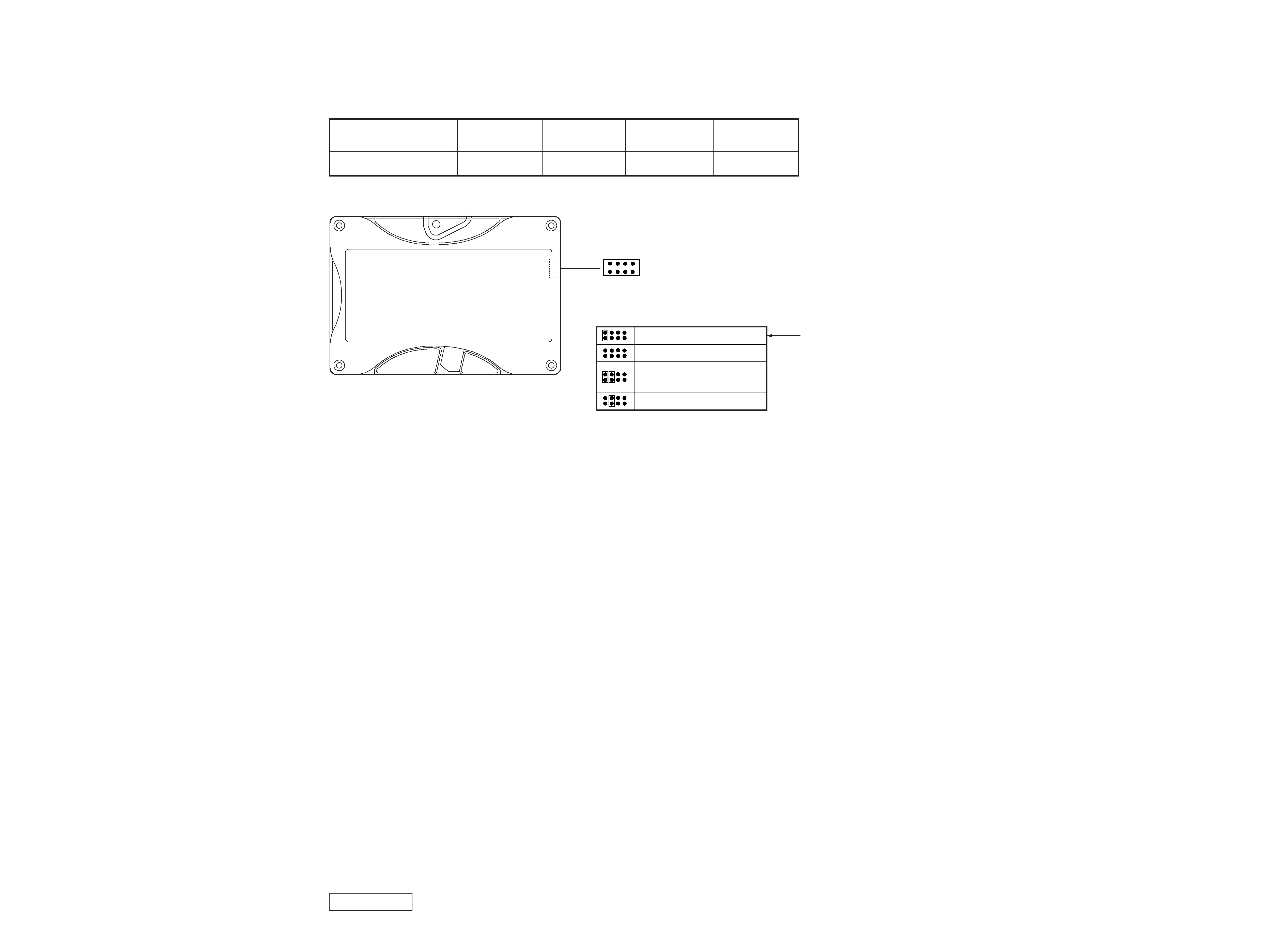
5-1.
JUMPER SETTING ON HARD DISK DRIVE
The hard disk drive of service parts can be used without changing factory jumper setting, when it was replaced for service.
Model
Part No.
Maker
Code
Capacity
(formatted)
PCV-RX462DS
A-8048-262-A
Seagate
ST340823A
40 GB
Master or single drive
Drive is a slave
Master with a non-ATA
compatible slave
Enable cable select
1
7
2
8
Factory setting
Master/Slave selection
Jumper setting
PCV-RX462DS (UC)
Confidential
S
11 4-645-944-01
SCREW (SW) (NO.6-32UNC)
S
12 1-959-912-31
HARNESS (IDE CD/DVD)
S
13 1-960-364-31
HARNESS (IDE/ATA100)
S
14 1-959-946-41
HARNESS (FDD)
S
15 1-960-947-31
HARNESS (USB/LUKE)
S
16 1-959-913-21
HARNESS (SW/LED)
S
17 8-749-019-34
RIMM 64MB (MC-4R64CPE6C-845)
S
18 A-8025-155-A
MOTHER BOARD (YA) ASSY (S)
S
19 4-648-911-31
PANEL, TOP
O
20 4-648-889-01
UPPER CHASSIS
O
21 X-4623-008-1
CD HOLDER ASSY
S
22 4-648-882-31
ESCUTCHEON (S)
S
23 A-8049-315-A
CD-RW DRIVE (160E-T3MM) ASSY (S)
S
24 7-682-903-01
SCREW +PWH 3X5
O
25 X-4623-521-1
CHASSIS ASSY, MAIN
S
26 4-648-910-01
PANEL, RIGHT
S
26 4-648-910-11
PANEL, RIGHT
S
28 A-8025-103-A
PANEL ASSY (UPPER) (for 2 BAY) (U)
S
31 A-8025-104-A
PANEL ASSY (LOWER) (U)
S
32 X-4623-809-1
AUDIO ASSY (U), DOOR
S
33 4-045-250-21
DAMPER
S
34 1-761-387-11
BOARD, SWX-66
S
37 1-681-235-11
BOARD, CNX-138
O
38 X-4623-522-1
BRACKET AV ASSY
S
39 1-959-197-21
HARNESS (1394)
O
41 X-4623-010-2
BRACKET ASSY, HDD
S
42 A-8048-262-A
HDD/S-U5 (40GB) ASSY (S)
S
43 1-761-430-11
MODEM CARD (LOW PROFILE)
S
46 1-772-251-41
FDD
O
47 X-4623-520-1
BRACKET ASSY, FDD
O
48 X-4623-108-1
BRACKET (ATX) ASSY (1394)
O
49 4-654-832-01
LABEL, I/O
O
50 4-654-835-01
LABEL, SLOT
O
51 4-650-918-11
SPACER, MB
S
52 4-643-547-01
FOOT
O
53 4-640-554-11
CABLE CLAMP
O
54 4-640-554-21
CABLE CLAMP
S
55 1-761-406-11
CARD, VGA (GE FORCE2)
S
58 4-648-913-11
ESCUTCHEON (P)
S
59 1-796-084-11
DVD-ROM/P-G6TR (16X)
O
60 4-657-277-01
LABEL, ID
O
67 4-651-252-01
SHIELD, LED
O
74 4-650-779-01
PANEL, PCI SLOT
S
78 1-761-410-11
CRIMM (YO)
O
79 4-656-276-01
LABEL, SAFETY
S
80 A-8049-313-A
HDD/M-LEO (80GB) ASSY (S)
for CTO Option
S
81 8-749-019-79
RIMM 64MB (MR16R0824BN1-CK8)
for CTO Option
S
81 6-600-004-01
RIMM 128MB (MR16R0828BN1-CK8)
for CTO Option
O
84 4-078-636-01
GASKET (A)
O
85 4-640-554-01
CABLE CLAMP
O
90 4-656-049-01
SPACER, LEFT PANEL
S
91 1-761-444-11
CARD, MODEM for CTO Option
O
7-300-000-40
SILICON COMPOUND (G-765) 90G
* Used on replacing CPU, heat sink.
(Refer to page 2-14)
19
20
21
58
59
22
23
24
25
31
32
33
54
37
11
53
52
51
46
24
55
43
84
47
50
49
48
11
2
1
A
A
26
11
67
34
60
74
11
17
6
14
11 15
16
12
13
8
39
18
78
11
42
41
11
11
HDD
CTO
80
38
B
81
RIMM
CTO
B
5
5
4
3
84
90
85
MODEM
CTO
91
28
79
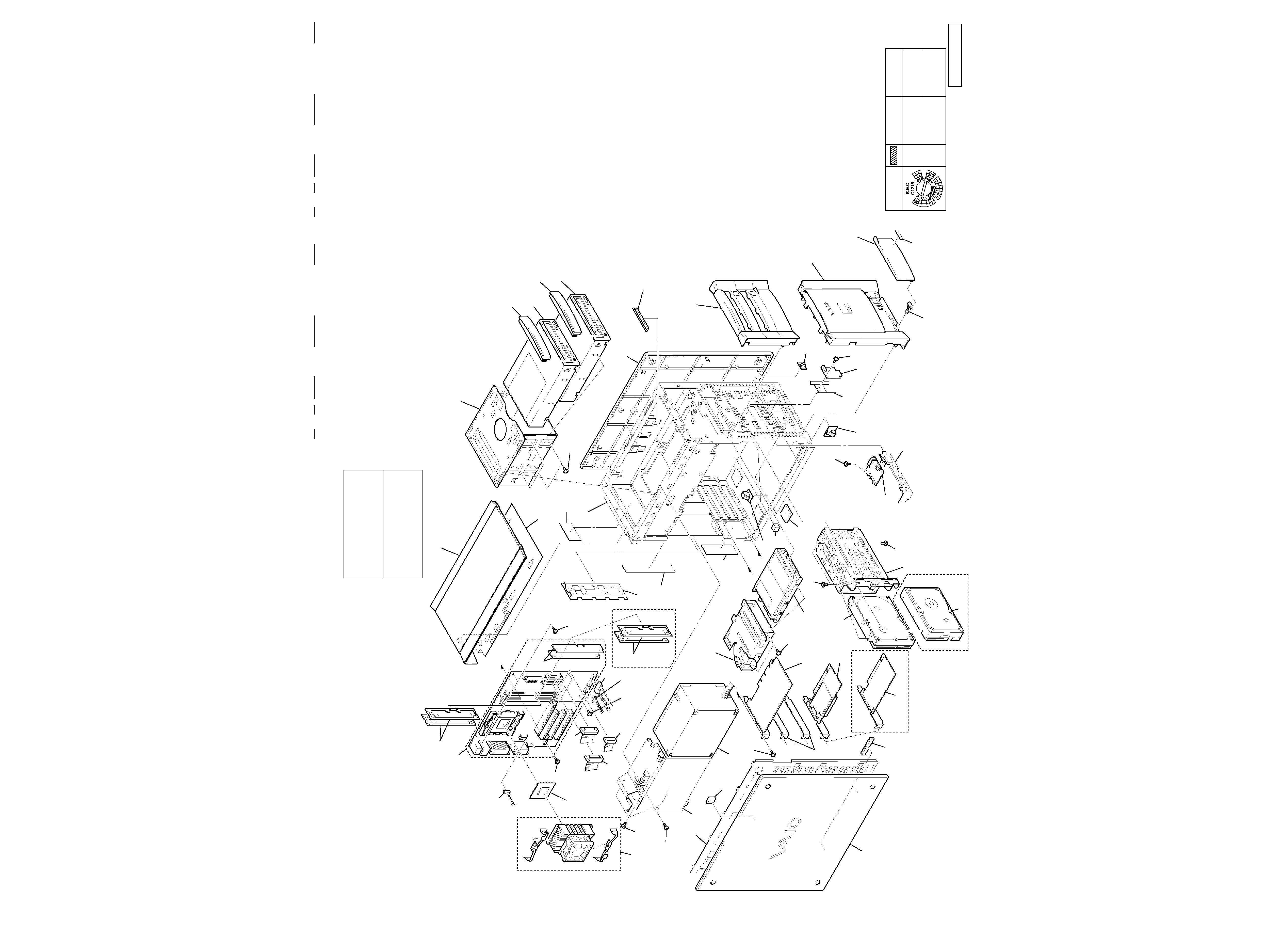
SECTION 7
REPAIR PARTS LIST
NOTE:
· The parts listed here are for service, and therefore they may be different
from the parts shown in circuit diagrams or used in the set.
· The category "O" in S/P column denotes that the parts are not always
stocked.
· The parts with
marking are stocked at the Division.
7-1.
EXPLODED VIEWS AND PARTS LIST
Les composants identifiés par une
marque 0 sont critiquens pour la
sécurité.
Ne les remplacer que par une pièce
portant le numéro spécifié.
The components identified by
mark 0 or dotted line with mark
0 are critical for safety.
Replace only with part number
specified.
Ref.
S/P
No. Part No.
Description
Remark
Ref.
S/P
No. Part No.
Description
Remark
S
1 4-648-912-02
PANEL, LEFT
S
1 4-648-912-12
PANEL, LEFT
O
2 X-4623-012-1
LEFT CHASSIS ASSY
0S
3 1-468-601-13
POWER UNIT
0S
3 1-468-601-23
POWER UNIT
O
4 X-4623-542-1
BRACKET (PS (280W)) ASSY
O
4 X-4623-542-1
BRACKET (PS (280W)) ASSY
S
5 4-635-795-01
SCREW (NO.6-32UNC)
S
6 1-763-675-21
FAN, DC (WITH HEAT SINK)
S
8 A-8049-329-A
CPU (P4/1.3G/370/4SF) ASSY (S)
5
6
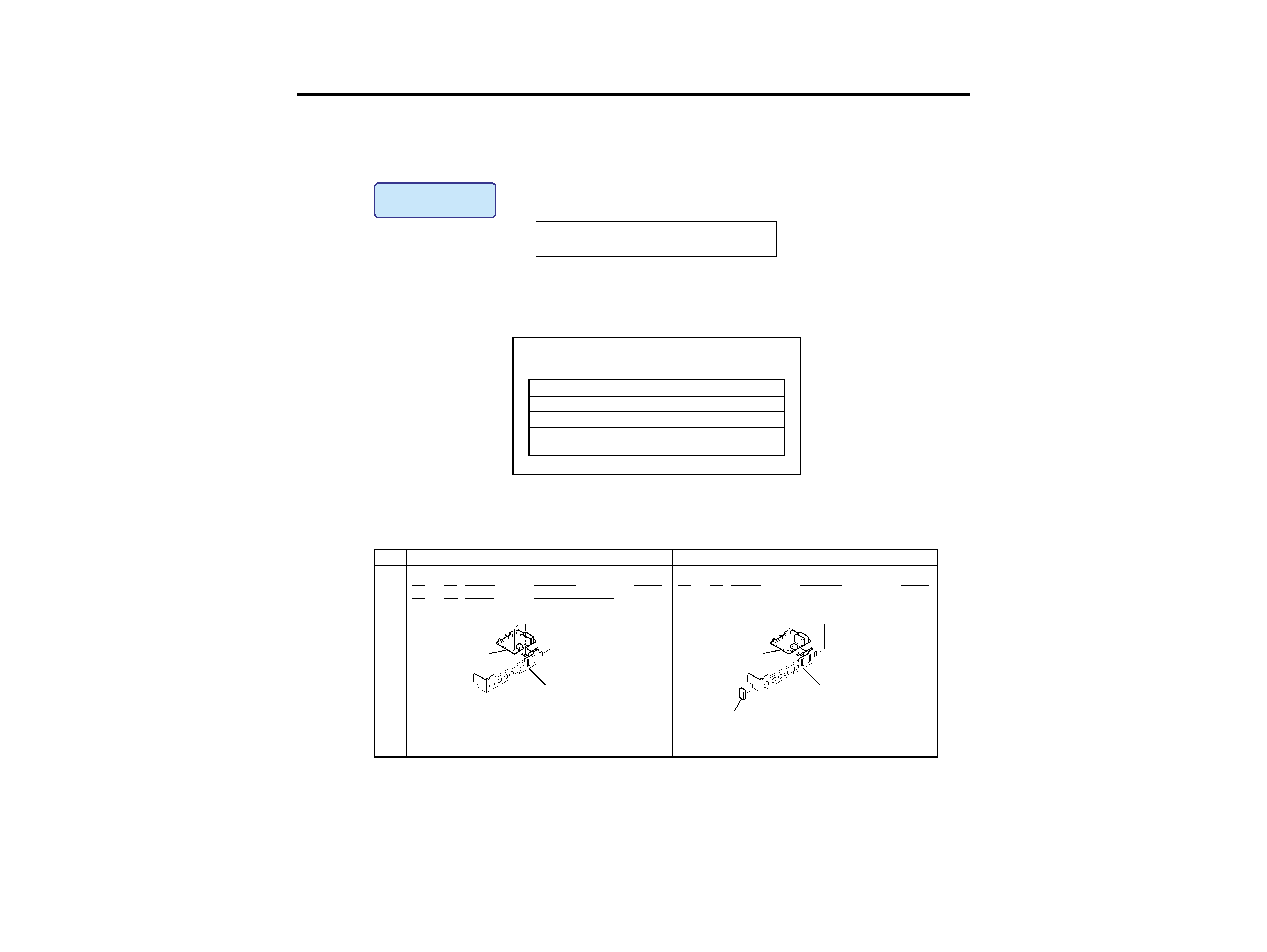
LEFT PANEL
(Ref. No. 1)
4-648-910-11
4-648-912-12
4-648-910-01
4-648-912-02
190H
VN30
RIGHT PANEL
(Ref. No. 26)
BACK SIDE
of PANEL
* Side panels (ref. no. 1 and 26) are different from by production
time.
When you change it, use right and left same thing in the table.