3-861-087-11(1)
© 1997 by Sony Corporation
Digital Audio
Recorder
Operating Instructions
Mode d'emploi
Bedienungsanleitung
EN
F
D
PCM-R300
2EN
INFORMATION
This equipment has been tested and
found to comply with the limits for a
Class B digital device, pursuant to Part
15 of the FCC Rules.
These limits are designed to provide
reasonable protection against harmful
interference in a residential installation.
This equipment generates, uses, and can
radiate radio frequency energy and, if
not installed and used in accordance
with the instructions, may cause harmful
interference to radio communications.
However, there is no guarantee that
interference will not occur in a particular
installation. If this equipment does cause
harmful interference to radio or
television reception, which can be
determined by turning the equipment off
and on, the user is encouraged to try to
correct the interference by one or more of
the following measures:
-- Reorient or relocate the receiving
antenna.
-- Increase the separation between the
equipment and receiver.
-- Connect the equipment into an
outlet on a circuit different from
that to which the receiver is
connected.
-- Consult the dealer or an
experienced radio/TV technician
for help.
CAUTION
You are cautioned that any changes or
modifications not expressly approved in
this manual could void your authority to
operate this equipment.
For the customers in Canada
CAUTION
TO PREVENT ELECTRIC SHOCK, DO
NOT USE THIS POLARIZED AC PLUG
WITH AN EXTENSION CORD,
RECEPTACLE OR OTHER OUTLET
UNLESS THE BLADES CAN BE FULLY
INSERTED TO PREVENT BLADE
EXPOSURE.
Voor de klanten in Nederland
Bij dit produkt zijn
batterijen geleverd.
Wanneer deze leeg zijn,
moet u ze niet weggooien
maar inleveren als KCA.
WARNING
To prevent fire or shock
hazard, do not expose the unit
to rain or moisture.
To avoid electrical shock, do
not open the cabinet. Refer
servicing to qualified
personnel only.
For the customers in the
United States
This symbol is intended to alert the user
to the presence of uninsulated
"dangerous voltage" within the
product's enclosure that may be of
sufficient magnitude to constitute a risk
of electric shock to persons.
This symbol is intended to alert the user
to the presence of important operating
and maintenance (servicing)
instructions in the literature
accompanying the appliance.
Owner's Record
The model and serial numbers are
located on the rear of the unit.
Record the serial number in the space
provided below. Refer to them
whenever you call upon your Sony
dealer regarding this product.
Model No. PCM-R300
Serial No.
Welcome!
Thank you for purchasing the Sony
Digital Audio Recorder. Before
operating the unit, please read this
manual thoroughly and retain it for
future reference.
The PCM-R300 has the following
features:
· SBM (Super Bit Mapping) function
· Three sampling frequencies (48 kHz,
44.1 kHz, 32 kHz)
· Recording and playback in long-play
mode
· Sub codes
Start IDs, skip IDs, an end ID, and
program numbers written to the tape
allow you to locate tracks quickly
· Easy menu operations using the
SELECT and DATA buttons that
allows you to make various settings
· Error rate counter
· See-through cassette compartment lid
A see-through cassette compartment
lid that allows you to view tape
operations during playback and
recording
· Rack mount adaptor
About This Manual
The instructions in this manual are for
PCM-R300.
Conventions
Instructions in this manual describe the
controls on the deck.
The following icons are used in this
manual:
z
Indicates useful information or
tips that make a task easier.
Z
Indicates a task that requires use
of the remote.

3EN
EN
TABLE OF CONTENTS
Getting Started
Unpacking 4
Rack Mounting 4
Hooking Up the System 5
Digital Interface 5
Playing a Tape 7
Recording on a Tape 8
Recording Operations
Things You Should Know Before Recording 10
Locating the End of the Recorded Portion (End Search) 10
Setting the Recording Mode 11
Using the SBM (Super Bit Mapping) Function 11
Inserting a Sound-Muted Section While Recording (Record Muting) 12
Playback Operations
About the Display 12
Locating a Track (AMS/Direct Access) 13
Playing Tracks Repeatedly (Repeat Play) 14
Playing Tracks Skipping Specific Portions During Playback (Skip Play) 14
Writing Sub Codes
About Sub Codes 15
Writing Sub Codes During Recording 15
Writing Sub Codes During Playback 16
Adjusting the Position of an Existing Start ID 17
Erasing Sub Codes 18
Renumbering the Program Numbers Automatically (Renumbering) 18
Menu Operations
Menu Operations 19
Additional Information
Precautions 21
Cleaning 21
Display Messages 22
Troubleshooting 22
Specifications 23
Index 25
4EN
Getting Started
Getting Started
Unpacking
Check that you have received the following supplied
items:
· AC power cord (1)
· Remote commander (remote) RM-D757 (1)
· Size-AA (R6) batteries (2)
· Rack mount adaptors (2)
· Screws (M5
× 12) (4)
· Decorative washers (4)
· Decorative panel (1)
· Tapping screws (3
× 8) (2)
· Operating instructions (1)
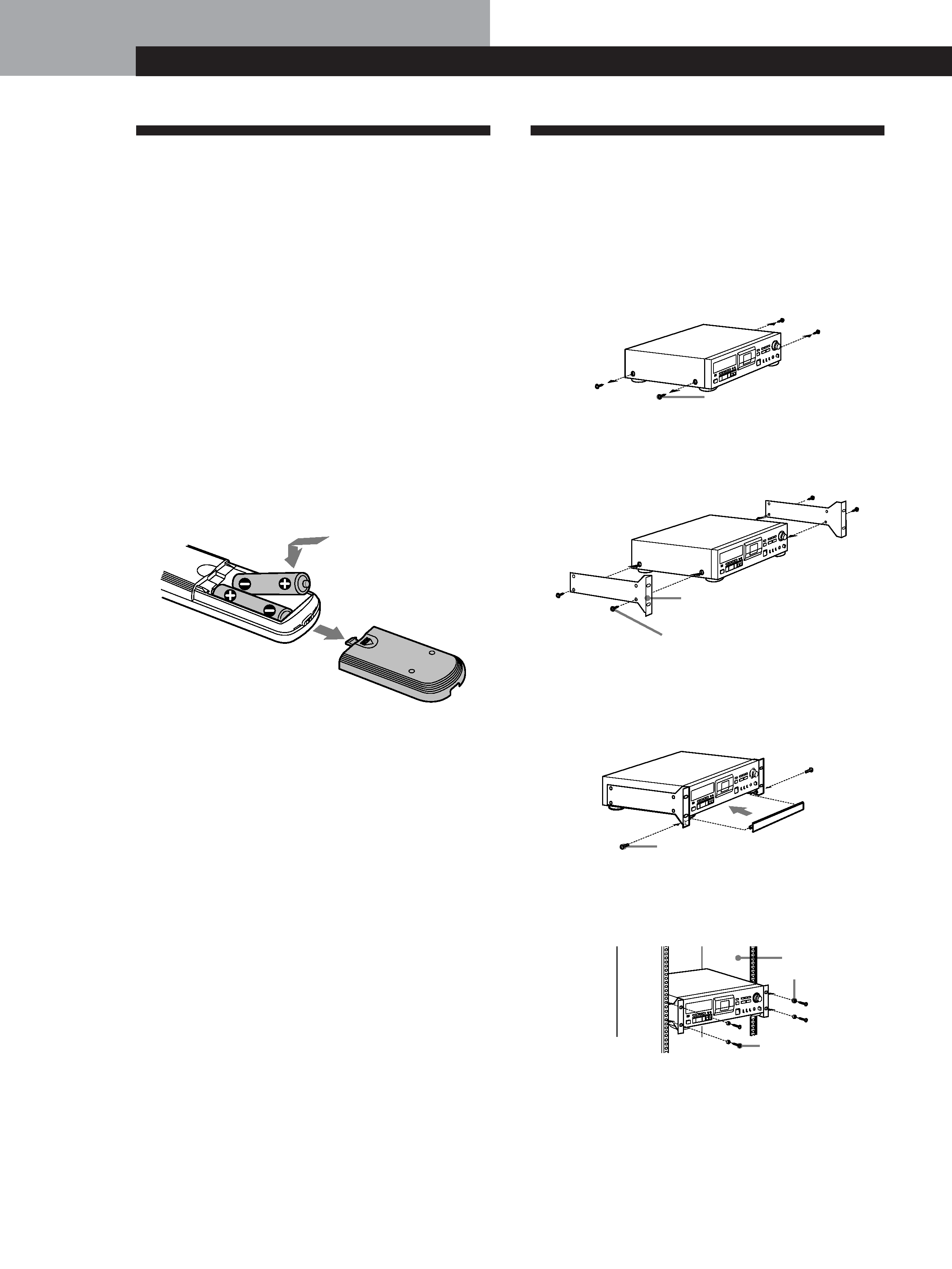
Inserting batteries into the remote
Insert two size-AA (R6) batteries, matching the + and
on the batteries with the markings inside the battery
compartment.
z When to replace the batteries
With normal use, batteries should last for about 6
months. When the remote no longer operates the deck,
replace both batteries.
Notes
· Do not leave the remote near an extremely hot or humid
place.
· Do not drop any foreign matter into the remote casing,
particularly when replacing the batteries.
· Do not expose the remote sensor to direct sunlight or
illumination as doing so may cause malfunction.
· When not using the remote for an extended period of time,
remove the batteries to avoid possible damage from
battery leakage and corrosion.
Rack Mounting
You can use the supplied rack mount adaptor to install
your deck in a 19-inch 3U-size rack. Be sure to turn the
deck off before you install it.
1 Remove the screws (M3
× 10) from the sides of the
deck.
2 Position the rack mount adaptors onto the sides of
the deck as shown below and secure them with
the screws removed in step 1.
3 If necessary, attach the decorative panel with the
tapping screws (3
× 8).
The decorative panel covers the space that forms
below the deck.
4 Insert the deck into the rack and secure it with the
supplied decorative washers and screws (M5
×
12).
Rack mount adaptor
Screw (M3
× 10)
Tapping screw (3
× 8)
Screw (M5
× 12)
Decorative washer
Screw (M3
× 10)
Rack
5EN
Getting Started
Getting Started
Hooking Up the System
This section describes how to hook up your deck to an
amplifier, CD player, MD deck, or other audio
components. Be sure to turn off the power to each
component before making the connections.
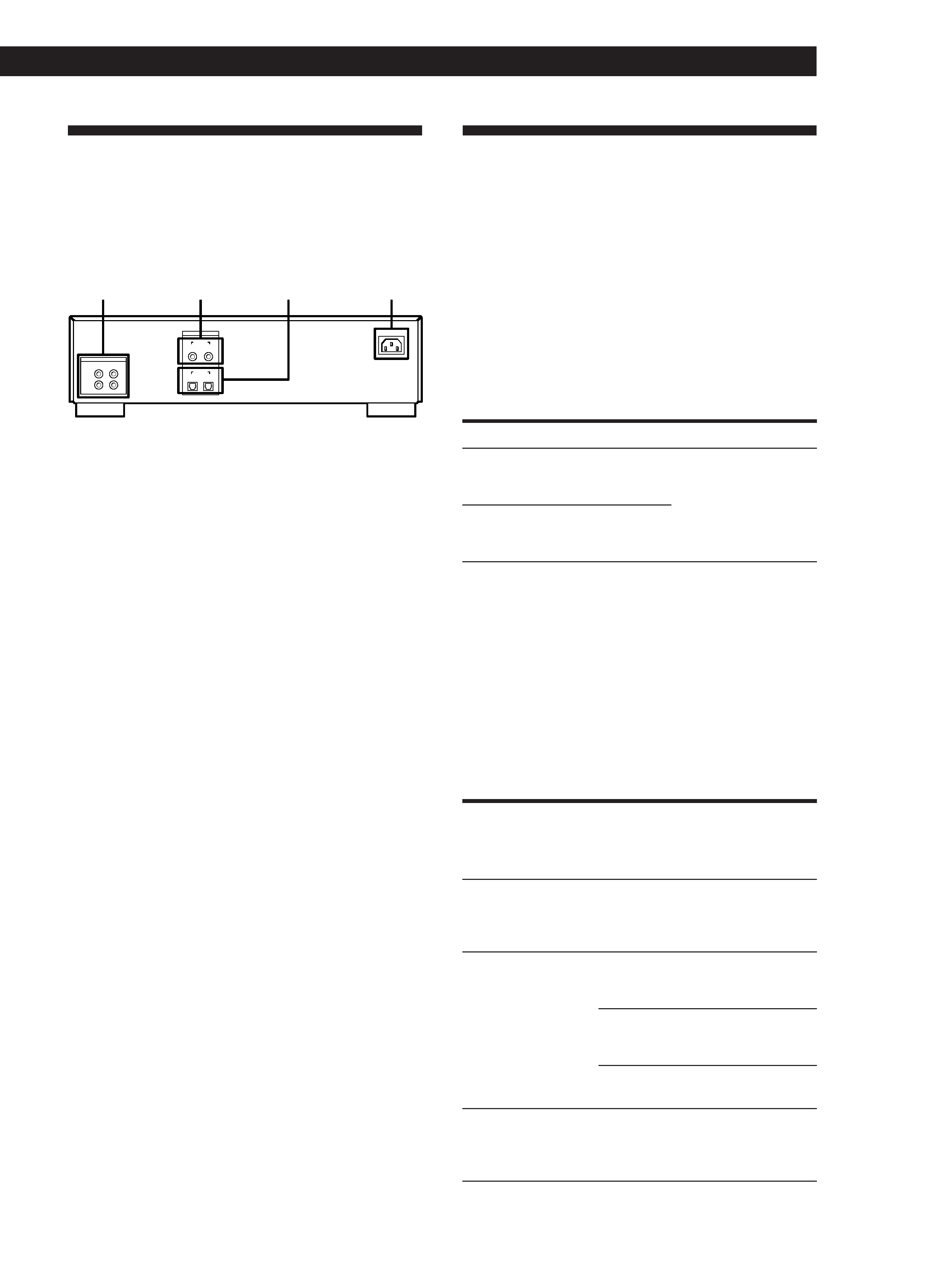
IN
ANALOG (LINE)
CH-1
CH-2
(L)
(R)
OUT
COAXIAL
DIGITAL
/ AC IN
IN
OUT
OPTICAL
IN
OUT
1
2
4
3
1 ANALOG (LINE) IN/OUT jacks
2 DIGITAL COAXIAL IN/OUT jacks
3 DIGITAL OPTICAL IN/OUT jacks
4 AC IN socket
Analog connections
Use phono-plug audio connecting cables (not
supplied).
Digital connections
For connections through the DIGITAL COAXIAL IN/
OUT jacks
Use coaxial digital connecting cables (not supplied).
For connections through the DIGITAL OPTICAL IN/
OUT jacks
Use optical digital connecting cables (not supplied).
Connecting the AC power cord
Connect the AC power cord (supplied) to the AC IN
socket on the rear panel and connect the plug on the
other end to a wall outlet.
Digital Interface
Digital input and output jacks
· The following table shows signal formats that
correspond to the input and output jacks on the
deck.
· The DIGITAL COAXIAL IN jack accepts not only the
consumer version of the IEC-958 international digital
audio interface standard, but also the broadcasting
studio version of the IEC-958 standard used by such
DAT decks as the PCM-2300, PCM-2700 or PCM-
2700A.
Type
Input signal format
Output signal format
DIGITAL
COAXIAL/
OPTICAL
IEC-958 for consumer
use
IEC-958 for
consumer use
DIGITAL
COAXIAL
IEC-958 for
broadcasting studio
use
Copy information during recording
· Copy information that is recorded on tape during
recording varies according to the input jack used and
the signal format, as shown in the table below.
· In the case of the IEC-958 for broadcasting studio
use, the digital signal carries no copy information.
· As for the IEC-958 for consumer use, three types of
copy information exists: copying possible, first-
generation copy permitted, and copying prohibited
(Serial Copy Management System).
Input jack
Signal
format
Copy
information
carried by
digital signal
Recording
capability
on this
deck
Copy
information
recorded on
tape
DIGITAL
COAXIAL
IEC-958 for
broadcasting
studio use
None
Possible
Determined
by menu
setting (page
19)
DIGITAL
COAXIAL/
OPTICAL
IEC-958 for
consumer
use
Permitted
Possible
Permitted (ID
6:00)
First-
generation
only
Possible
Prohibited
(ID 6:10)
Prohibited Possible
Prohibited
(ID 6:10)
ANALOG
(LINE)
--
--
Possible
Determined
by menu
setting (page
19)