Conf
idential
SERVICE MANUAL
US Model
Canadian Model
PCGA-DSD5/DSM5
S400
9-874-401-13
CD-RW/DVD Docking Station
DVD Docking Station
Drive performance
CD-RW/DVD Docking Station (PCGA-DSM5)
Reading speed: 24X max. CD-ROM/CD-R reading,
12X max. CD-RW reading,
8X max. DVD-ROM reading,
Writing speed: 8X max. CD-R writing,
4X max. CD-RW writing,
Disk diameter 4 3/4 inch (12cm), 3inch (8cm)
Multi-session correspondence
DVD Docking Station (PCGA-DSD5)
Reading speed: 24X max. CD-ROM reading,
: 8X max. DVD-ROM reading,
Disk diameter 4 3/4 inch (12cm), 3inch (8cm)
Multi-session correspondence
Floppy disk drive
3.5" 1.44MB/720KB
Connectors
SERIAL Connector: RS-232C, D-SUB 9 pin (1)
PRINTER Connector: ECP, D-SUB 25 pin (1)
MONITOR Connector: analog RGB, mini D-SUB 15 pin (1)
USB Connector: USB 4 pin (2)
i.LINK (IEEE 1394) Connector S400 4pin(1) S400=400Mbps
NETWORK Connector: RJ-45 (1)*
Docking Connector: Dedicated connector 100pin(1)
Power source AC adapter or battery pack (only when it is attached to the
notebook computer)
Operating temperature
41
°F to 95 °F (5 °C to 35 °C)
(temperature gradient less than 18
°F (10 °C)/hour)
Operating humidity
20 % to 80 % (not condensed), provided that humidity is
less than 65 % at 95
°F (35 °C)
(hygrometer reading of less than 84
°F (29 °C))
Storage temperature
4
°F to 140 °F (20 °C to 60 °C)
(temperature gradient less than 18
°F (10 °C)/hour)
Storage humidity
10 % to 90 % (not condensed), provided that humidity is
less than 20 % at 140
°F (60 °C)
(hygrometer reading of less than 95
°F (35 °C))
Dimensions
Approx. 11.0
× 0.8(0.9 backside) × 9.3 inches (w/h/d)
(Approx. 279.5
× 18.5(21.5 backside) × 235.0 mm)
(the projecting parts are not included)
Mass
PCGA-DSM5 2.38 lbs. (1,080 g)
PCGA-DSD5 2.27 lbs. (1,030 g)
Supplied accessories
Operating instructions (1)
Warranty card (1)
*There is a NETWORK Connector for the correspondence to 10BASE-T,
100BASE-TX.
Design and specifications are subject to change without notice.
Specifications
Ver. 3 2004G
Revision History

2
PCGA-DSD5/DSM5 (UC)
Confidential
Information in this document is subject to change without notice.
Sony and VAIO are trademarks of Sony. Microsoft, MS-DOS,
Windows, the Windows 95, Windows 98, Windows 2000 and
Windows ME logo are trademarks of Microsoft Corporation.
All other trademarks are trademarks or registered trademarks of
their respective owners. Other trademarks and trade names may be
used in this document to refer to the entitles claiming the marks and
names or their produces. Sony Corporation disclaims any proprietary
interest in trademarks and trade names other than its own.
Service and Inspection Precautions
1. Obey precautionary markings and instructions
Labels and stamps on the cabinet, chassis, and components identify areas
requiring special precautions. Be sure to observe these precautions, as
well as all precautions listed in the operating manual and other associated
documents.
2. Use designated parts only
The set's components possess important safety characteristics, such as
noncombustibility and the ability to tolerate large voltages. Be sure that
replacement parts possess the same safety characteristics as the originals.
Also remember that the 0 mark, which appears in circuit diagrams and
parts lists, denotes components that have particularly important safety
functions; be extra sure to use only the designated components.
3. Always follow the original design when
mounting parts and routing wires
The original layout includes various safety features, such as inclusion of
insulating materials (tubes and tape) and the mounting of parts above the
printer board. In addition, internal wiring has been routed and clamped so
as to keep it away from hot or high-voltage parts. When mounting parts or
routing wires, therefore, be sure to duplicate the original layout.
4. Inspect after completing service
After servicing, inspect to make sure that all screws, components, and wiring
have been returned to their original condition. Also check the area around
the repair location to ensure that repair work has caused no damage, and
confirm safety.
5. When replacing chip components...
Never reuse components. Also remember that the negative side of tantalum
capacitors is easily damaged by heat.
6. When handling flexible print boards...
· The temperature of the soldering-iron tip should be about 270C.
· Do not apply the tip more than three times to the same pattern.
· Handle patterns with care; never apply force.
Caution: Remember that hard disk drives are easily damaged by
vibration. Always handle with care.
Caution Markings for Lithium/Ion Battery - The following or similar
texts shall be provided on battery pack of equipment or in both the
operating and the service instructions.
CAUTION: Danger of explosion if battery is incorrectly replaced.
Replace only with the same or equivalent type recommended by
the manufacturer. Discard used batteries according to the
manufacturer's instructions.
CAUTION: The battery pack used in this device may present a fire
or chemical burn hazard if mistreated. Do not disassemble, heat
above 100°C (212°F) or incinerate.
Dispose of used battery promptly.
Keep away from children.
CAUTION: Changing the back up battery.
· Overcharging, short circuiting, reverse charging, multilation
or incineration of the cells must bi avoided to prevent one or
more of the following occurrences; release of toxic materials,
release of hydrogen and/or oxygen gas, rise in surface
temperature.
· If a cell has leaked or vented, it should be replaced
immediately while avoiding to touch it without any protection.

3
PCGA-DSD5/DSM5 (UC)
Confidential
TABLE OF CONTENTS
Section
Title
Page
CHAPTER 1. GENERAL
1-1. Locating Controls and Connectors .................................. 1-1
1-2. Attention of i.LINK ......................................................... 1-2
(to 1-2)
CHAPTER 2. REMOVAL
2-1. Flowchart ......................................................................... 2-1
2-2. Main Electrical Parts Location Diagram ......................... 2-1
2-3. Removal ........................................................................... 2-2
1.
Housing (Top) Assy ......................................................... 2-2
2.
COMBO Drive, DVD-ROM ............................................ 2-2
3.
FDD ................................................................................. 2-3
4.
IRX-146 Board ................................................................ 2-3
5.
CNX-130 Board ............................................................... 2-4
6.
SWX-75 Board ................................................................ 2-4
7.
CNX-132 Board ............................................................... 2-5
(to 2-5)
CHAPTER 3. SELF DIAGNOSTICS .......................... 3-1
Please confirm "Self Diagnostics" method which will be informed
you with distribution of "Self Diagnostics" software.
CHAPTER 4. BLOCK DIAGRAM ............................... 4-1
(to 4-2)
CHAPTER 5. FRAME HARNESS DIAGRAM ........ 5-1
(to 5-2)
CHAPTER 6. EXPLODED VIEWS AND
PARTS LIST
6-1. Main Section .................................................................... 6-1
6-2. Accessories ...................................................................... 6-4
(to 6-4)
·
Abbreviations
UC : US model / Canadian model
1-1
PCGA-DSD5/DSM5 (UC)
Confidential
CHAPTER 1.
GENERAL
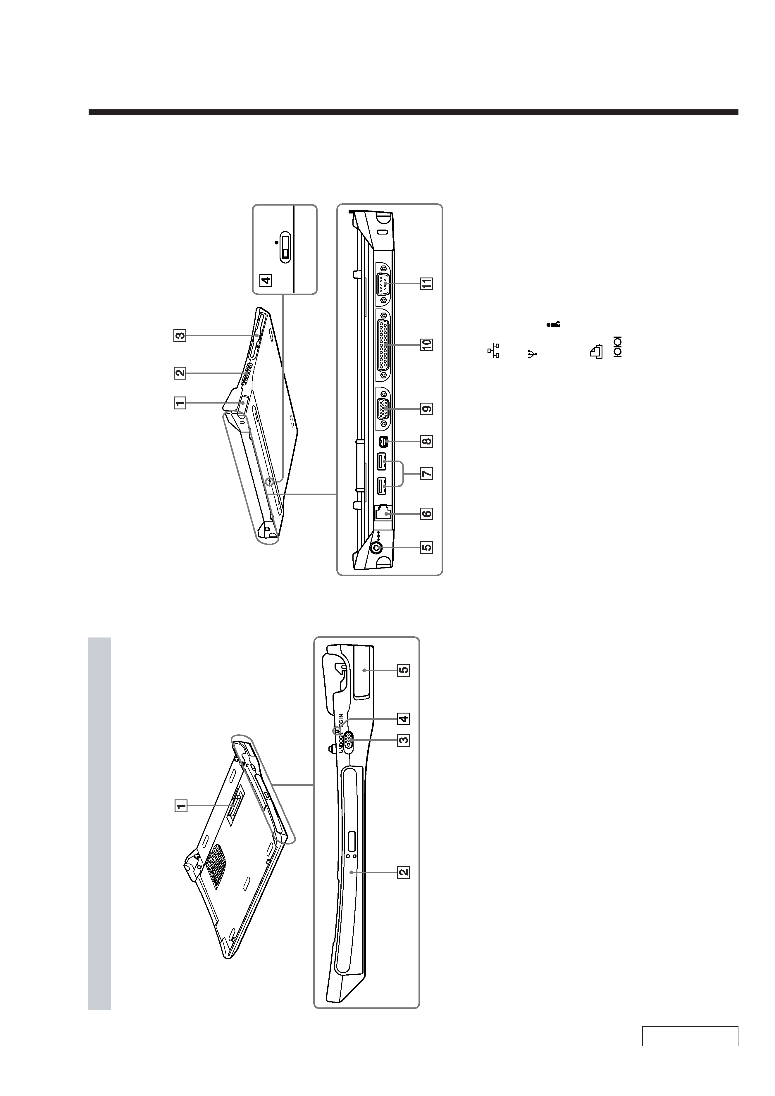
1-1. Locating Controls and Connectors
61
Docking
Station
Top/Right
Side
1
Docking
connector
2
PCGA-DSM5
CD-RW/DVD-ROM
combo
drive
PCGA-DSD5
DVD-ROM
drive
3
UNDOCK
switch
(page
66)
4
DC
IN
lamp
(page
65)
5
Release
lever
(page
67)
Docking
station
top
Docking
station
right
side
Locating
Controls
and
Connectors
62
Docking
Station
Left
Side/Rear
1
Release
lever
(page
67)
2
Ventilator
3
Floppy
disk
drive
4
i.LINK
network
switch
(page
91)
5
!
(DC
IN)
connector
(page
65)
6
(network)
connector
(page
6)
7
USB
connector
8
S400
i.LINK
connector
9
a
MONITOR
connector
0
PRINTER
connector
qa
SERIAL
connector
Docking
station
left
side
Docking
station
rear

1-2
PCGA-DSD5/DSM5 (UC)
Confidential
(END)
1-2. Attention of i.LINK
The i.LINK compatible unit connected to this set is not recognized. Or,
the message such as "Operation is disabled, as DV unit is not con-
nected or the power is not turned on" is displayed.
t Disconnect the i.LINK cable once, and reconnect it. For further informa-
tion, see "Connecting i.LINK unit" of "Data transfer to i.LINK unit" in the
"Extend" of the Online Manual for this set.
The unit connected to the i.LINK connector on the docking station does
not operate normally.
t Use the i.LINK connector on this set.
The operation of i.LINK compatible unit connected to this set stopped.
t Finish the operation of the i.LINK compatible unit first, when removing
the docking station during the connection of i.LINK compatible unit.
The message "Recording to DV unit failed. Retry after checking the DV
unit for power supply and connection state" is displayed during the
recording on the tape using the "DVgate" software.
t Check if the power and connection cables are connected correctly to
the DV unit. Continuous recording may cause a recording failure even if
the unit is connected correctly. In such a case, restart this set after exit-
ing all of the software.
To use the set in more comfortable environment, it is recommended to
extend the memory. For further information, see "Extending the memory"
(page 109).
The frames drop during the use of "DVgate" software.
t The frames may drop depending on the operating condition. In such a
case, extend the memory. For further information, see "Extending the
memory" (page 109).