Hong Kong Model
Singapore Model
SERVICE MANUAL
PORTABLE DVD PLAYER
SPECIFICATIONS
f
9-928-108-21
PBD-V30
RM-PBD1
System
System
Portable DVD Player
Laser
Semiconductor laser
Signal format system
NTSC color system, Macrovision
Disc
Compatible discs
· DVD VIDEO (NTSC)
· VIDEO CD (NTSC/PAL)
· AUDIO CD (CD-DA)
· CD-R
Disc diameter
12 cm (43/4 inch), 8 cm (3 inch)
Audio characteristics
Frequency response
DVD (PCM): 20 Hz to 44 kHz
(+1.0 dB to 3.0 dB)
CD: 20 Hz to 20 kHz
(+1.0 dB to 2.0 dB)
Signal-to-noise ratio (S/N)
More than 85 dB
High wave distortion rate
Less than 0.02%
Dynamic range
More than 88 dB
Wow and flutter
Less than detected value
(±0.001% W PEAK)
Outputs
Jack name Jack type Maximum Load
output
impedance
levels
A/V
Stereo
1 Vrms
Audio/Vrms
OUT
mini jack
47 k
Video/Vpp
75
terminated
PCM/
Optical
17 dBm
Wave length:
DOLBY
output
660 nm
DIGITAL
connector
S VIDEO
4-pin
Y:1.0
75
sync
OUT
mini DIN
Vp-p
negative
C:0.286
75
Vp-p
terminated
PHONES
Stereo
12 mV
16
mini jack
+
12 mV
General
Power requirements
· Power supply jack
DC IN 10V jack accepts the AC-PB1 AC power
adapter (supplied), AC 220-240 V, 50/60 Hz
· Battery pack (not supplied)
Power consumption
AC 220-240 V, 50 Hz, 0.18 A (max, AC power
adapter)
DC 10 V 1.1 A (max, DVD VIDEO playback with
the AC power adapter)
Dimensions (approx.)
149.6
× 33.5 × 182.3 mm
(6
× 13/8 × 71/4 inches) (w/h/d)
Mass (approx.)
570 g (1 lb 4 oz) (player only)
Operating temperature
5
°C to 35 °C (41°F to 95°F)
Operating humidity
5% to 80%
Environment
Temperature
20
°C to 55°C (4°F to 131°F)
Humidity
15% to 90% Rh
Supplied accessories
· Audio/video cable (stereo mini plug × 1 phono
plug
× 3) (1)
· AC-PBD1 AC power adapter (1)
· RM-PBD1 remote commander (remote) (1)
Optionl accessories
· Battery pack
NP-F750/F950
· AC battery changer
AC-V700
· DC battery changer
DC-V700
· Optical digital cable
POC-15B/15AB
· Headphones
MDR-605LP
Design and specifications are subject to change without
notice.

-- 2 --
SAFETY-RELATED COMPONENT WARNING!!
COMPONENTS IDENTIFIED BY MARK
! OR DOTTED LINE WITH
MARK
! ON THE SCHEMATIC DIAGRAMS AND IN THE PARTS
LIST ARE CRITICAL TO SAFE OPERATION. REPLACE THESE
COMPONENTS WITH SONY PARTS WHOSE PART NUMBERS
APPEAR AS SHOWN IN THIS MANUAL OR IN SUPPLEMENTS
PUBLISHED BY SONY.
TABLE OF CONTENTS
SERVICE NOTE ·························································· 3
1.
GENERAL ·································································· 1-1
2.
DISASSEMBLY
2-1.
SUB BOARD ································································· 2-1
2-2.
DVD MECHANISM (DVDM-D50), MAIN BOARD ·· 2-1
2-3.
UPPER LID ASSEMBLY ·············································· 2-2
2-4.
OCONTROL FLEXIBLE BOARD ······························· 2-2
3.
BLOCK DIAGRAMS
3-1.
OVERALL BLOCK DIAGRAM ··································· 3-1
3-2.
RF SERVO BLOCK DIAGRAM ··································· 3-3
3-3.
SCSI INTERFACE BLOCK DIAGRAM ······················ 3-5
3-4.
VIDEO/AUDIO BLOCK DIAGRAM ··························· 3-7
3-5.
SYSTEM CONTROL BLOCK DIAGRAM ·················· 3-9
3-6.
POWER BLOCK DIAGRAM ····································· 3-11
4.
PRINTED WIRING BOARDS AND SCHEMATIC
DIAGRAMS
· MAIN PRINTED WIRING BOARD ·························· 4-1
· MAIN (RF) SCHEMATIC DIAGRAM ······················ 4-5
· MAIN (DECODER) SCHEMATIC DIAGRAM ········ 4-8
· MAIN (CD DSP) SCHEMATIC DIAGRAM ··········· 4-11
· MAIN (SYSTEM CONTROL)
SCHEMATIC DIAGRAM ········································ 4-15
· MAIN (DVD DSP) SCHEMATIC DIAGRAM ········ 4-19
· MAIN (MOTOR DRIVER)
SCHEMATIC DIAGRAM ········································ 4-21
· MAIN (AV CONTROL) SCHEMATIC DIAGRAM
······················································································ 4-23
· MAIN (CONNECTOR) SCHEMATIC DIAGRAM
······················································································ 4-27
· MAIN (POWER SUPPLY)
SCHEMATIC DIAGRAM ········································ 4-29
· SUB PRINTED WIRING BOARD ··························· 4-31
· SUB (MPEG DECODER) SCHEMATIC DIAGRAM
······················································································ 4-33
· SUB (VIDEO D/A CONVERTER)
SCHEMATIC DIAGRAM ········································ 4-37
· SUB (CONNECTOR) SCHEMATIC DIAGRAM···· 4-39
· REMOTE PRINTED WIRING BOARD ·················· 4-41
· REMOTE SCHEMATIC DIAGRAM ······················· 4-42
Service Tool List
1
Extension cable 1
J-2500-129-1
Extension cable between the MAIN board CN453 and the SUB board CN454
2
Extension cable 2
J-2500-130-1
Extension cable between the MAIN board CN651 and the MD sled motor
3
FFC Extension cable
J-2500-131-1
Extension cable between the MAIN board CN652 and the MD spindle motor
4
Serial Extension cable
J-2500-132-1
RS-232C cable between the MAIN board CN802 PC (with conversion board)
5
Rewriting froppy disc
J-2500-133-1
Rewriting software
Ref.No.
Name
Part Code
Usage
1
234
5
5.
IC PIN FUNCTION DESCRIPTION
5-1.
SYSTEM CONTROL MICON
(MAIN BOARD IC801) ················································· 5-1
5-2.
A/V CONTROL MICON (MAIN BOARD IC901) ······· 5-3
6.
SELF DIAGNOSIS FUNCTION ·························· 6-1
7.
ELECTRICAL ADJUSTMENTS
7-1.
CHARGE VOLTAGE ADJUSTMENT ························· 7-1
7-2.
VIDEO ADJUSTMENT ················································· 7-1
8.
REPAIR PARTS LIST
8-1.
EXPLODED VIEWS
8-1-1. LOWER CABINET SECTION ······································ 8-1
8-1-2. UPPER CABINET SECTION ······································· 8-2
8-2.
ELECTRICAL PARTS LIST ········································· 8-3
-- 3 --
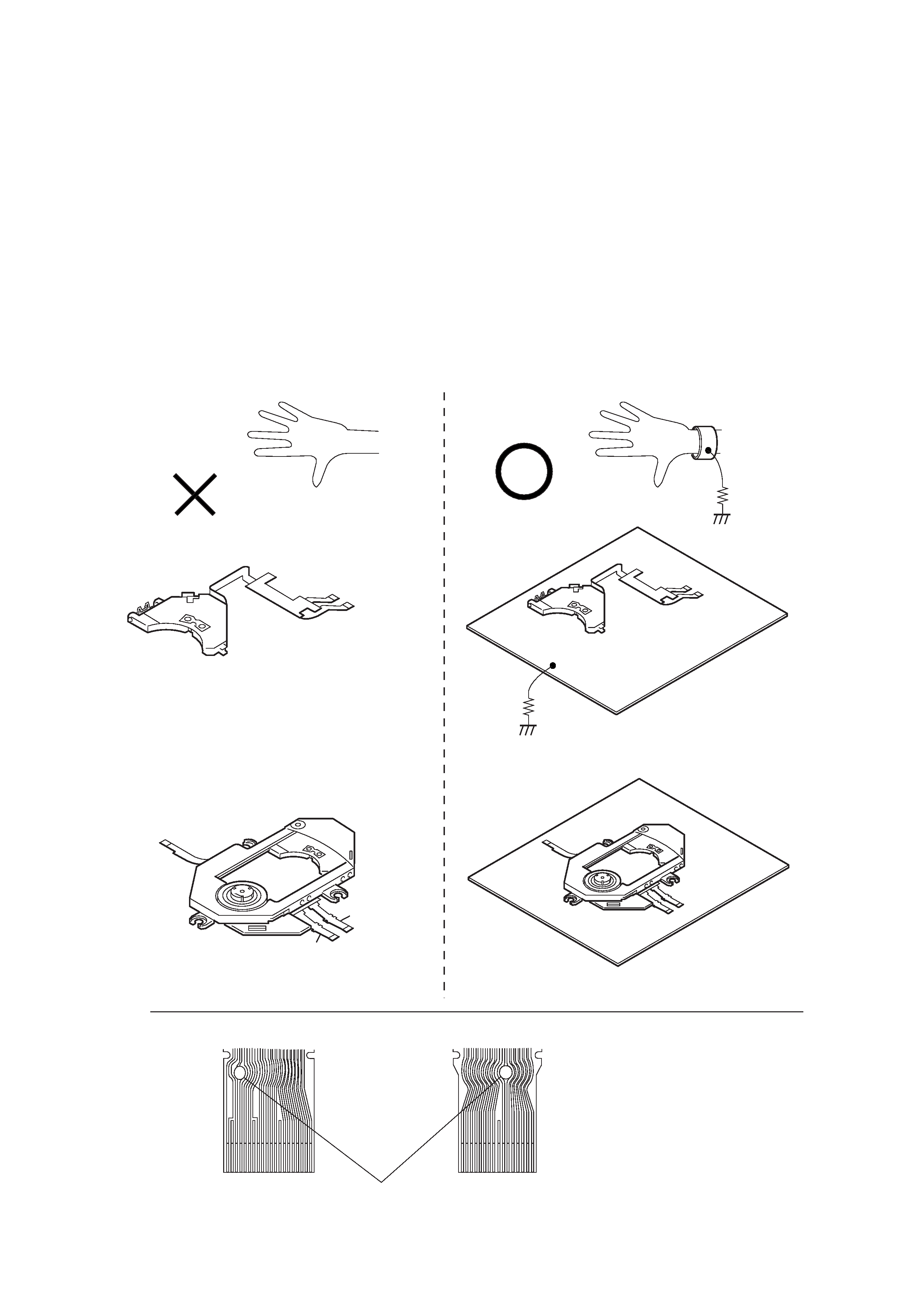
Do not unpack or install or repair the optical pickup unit KHS-190A series without the grounding
processing as shown below.
1. Grounding the human body
Be sure to wear a grounding wrist strap (10
or less) around your wrist to ground the static electricity accumulated in human body.
2. Grounding the work bend
Place a conductive sheet (10
or less) or a copper plate on the work bench on which the merchandise to be repaired is placed. (The black
sheet that is used for packaging the optical pickup unit, is a conductive sheet.) Connect the conductive sheet or the copper plate to an
electrical ground.
3. Be careful that your clothes do not touch the optical pickup unit because the static electricity accumulated in your clothes are not
grounded through the grounding wrist strap.
4. When the optical pickup unit is shipped from the factory, the laser diode pins are shorted to protect the laser diode from static electricity.
To open the shorting, connect the laser diode to an appropriate APC (Automatic laser Power Control) circuit first, then remove the
soldering quickly with a soldering iron having the insulation resistance of 1M or more.
SERVICE NOTE
1 Grounding wrist strap
2 Conductive sheet or copper plate
1M
1M
B
A
AB
Flexible board
Optical pickup unit (KHS-190A/J1N)
Optical pickup unit
DVD mechanism (DVDM-D50)
[Caution]
After installing the optical pickup unit, remove soldering.


1-1
PBD-V30
SECTION 1
GENERAL
This section is extracted from
instruction manual.3-864-642-71
3
Table
of
contents
Compatible
disc
types
1-5
About
this
manual
1-7
Getting
started
Hooking
up
the
system
1-8
Initial
setups
befor
eusing
the
player
1-9
Basic
operations
Playing
a
DVD
VIDEO
1-9
Playing
a
CD/VIDEO
CD
1-13
Additional
operations
Playing
r
epeatedly
(Repeat
Play)
1-17
Playing
in
random
or
der
(Shuf
fle
Play)
1-20
Cr
eating
your
own
pr
ogram
(Pr
ogram
Play)
1-20
Resuming
playback
fr
om
the
point
wher
eyou
stopped
a
disc
(Resume
Play)
1-22
Changing
the
sound
1-23
Using
the
sub-titles
1-23
Changing
the
angles
1-24
Pr
eventing
accidental
pr
essing
of
the
buttons
1-25
Using
the
r
echar
geable
battery
pack
1-25
Using
the
audio
amplifier
1-27
Setting
and
adjustment
Basic
settings
(INITIAL
SETUP)
1-29
Limiting
playback
by
childr
en
(Par
ental
Contr
ol)
1-31
Additional
information
Pr
ecautions
1-33
Notes
on
discs
1-34
T
roubleshooting
1-34
Glossary
1-36
Index
to
parts
and
contr
ols
1-2
Language
code
list
1-37
INITIAL
SETUP
items
list
1-38
Self-diagnosis
function
1-2
2
WARNINGWARNING
To
prevent
fire
or
shock
hazard,
do
not
expose
the
player
to
rain
or
moisture.
The
equipment
should
be
installed
near
an
easily
accessible
outlet.
Manufactured
under
license
from
Dolby
Laboratories
Licensing
Corporation.
DOLBY,
the
double-D
symbol
a
,"PRO
LOGIC,"
and
AC-3
are
trademarks
of
Dolby
Laboratories
Licensing
Corporation.
W
elcome!
Thank
you
for
purchasing
the
Sony
Portable
DVD
Player.
Before
operating
the
player,
please
read
this
manual
thoroughly
and
retain
it
for
future
reference.