SERVICE MANUAL
PORTABLE MEMORY STICK AUDIO PLAYER
US Model
Canadian Model
AEP Model
UK Model
E Model
Australian Model
Chinese Model
SPECIFICATIONS
NW-MS9
Ver 1.2 2001.09
9-873-028-13
Sony Corporation
2001I0500-1
Personal Audio Company
C
2001.9
Shinagawa Tec Service Manual Production Group

2
NW-MS9
TABLE OF CONTENTS
1.
SERVICING NOTES ............................................... 3
2.
GENERAL ................................................................... 4
3.
DISASSEMBLY
3-1. Disassembly Flow ...........................................................
5
3-2. Case Block Assy ..............................................................
5
3-3. Case .................................................................................
6
3-4. Guide (LED) ....................................................................
7
3-5. Chassis (Main) Assy .......................................................
7
3-6. "Console Unit", "SUB Board", "MAIN Board" ............
8
3-7. Console Assy ...................................................................
8
3-8. CONSOLE Board ...........................................................
9
4.
TEST MODE .............................................................. 10
5.
DIAGRAMS
5-1. Block Diagram MAIN Section .................................. 15
5-2. Block Diagram
DISPLAY/POWER SUPPLY Section ....................... 16
5-3. Note for Printed Wirinig Boards and
Schematic Diagrams ....................................................... 17
5-4. Printed Wiring Boards MAIN Section ...................... 19
5-5. Schematic Diagram MAIN Section (1/4) .................. 20
5-6. Schematic Diagram MAIN Section (2/4) .................. 21
5-7. Schematic Diagram MAIN Section (3/4) .................. 22
5-8. Schematic Diagram MAIN Section (4/4) .................. 23
5-9. Schematic Diagram SUB Section (1/2) ..................... 24
5-10. Schematic Diagram SUB Section (2/2) ..................... 25
5-11. Printed Wiring Board SUB Section ........................... 26
5-12. IC Pin Function Description ........................................... 31
6.
EXPLODED VIEWS
6-1. General Section ............................................................... 39
6-2. MAIN Board Section ...................................................... 40
7.
ELECTRICAL PARTS LIST ............................... 41
SAFETY-RELATED COMPONENT WARNING!!
COMPONENTS IDENTIFIED BY MARK 0 OR DOTTED
LINE WITH MARK 0 ON THE SCHEMATIC DIAGRAMS
AND IN THE PARTS LIST ARE CRITICAL TO SAFE
OPERATION. REPLACE THESE COMPONENTS WITH
SONY PARTS WHOSE PART NUMBERS APPEAR AS
SHOWN IN THIS MANUAL OR IN SUPPLEMENTS PUB-
LISHED BY SONY.
Notes on chip component replacement
· Never reuse a disconnected chip component.
· Notice that the minus side of a tantalum capacitor may be dam-
aged by heat.
Flexible Circuit Board Repairing
· Keep the temperature of the soldering iron around 270 °C dur-
ing repairing.
· Do not touch the soldering iron on the same conductor of the
circuit board (within 3 times).
· Be careful not to apply force on the conductor when soldering
or unsoldering.
UNLEADED SOLDER
Boards requiring use of unleaded solder are printed with the lead-
free mark (LF) indicating the solder contains no lead.
(Caution: Some printed circuit boards may not come printed with
the lead free mark due to their particular size)
: LEAD FREE MARK
Unleaded solder has the following characteristics.
· Unleaded solder melts at a temperature about 40 °C higher than
ordinary solder.
Ordinary soldering irons can be used but the iron tip has to be
applied to the solder joint for a slightly longer time.
Soldering irons using a temperature regulator should be set to
about 350 °C .
Caution: The printed pattern (copper foil) may peel away if the
heated tip is applied for too long, so be careful!
· Strong viscosity
Unleaded solder is more viscous (sticky, less prone to flow) than
ordinary solder so use caution not to let solder bridges occur
such as on IC pins, etc.
· Usable with ordinary solder
It is best to use only unleaded solder but unleaded solder may
also be added to ordinary solder.
NOTES:
· The recorded music is limited to private use only. Use of the music beyond this limit requires permission
of the copyright holders.
· Sony is not responsible for music files that are not saved on your computer due to unsuccessful recording
from CD or music downloading.
Other features
·Compact size, light weight.
·Skip-proof: you can enjoy uninterrupted enjoyment of music during physical activities such as
jogging or commuting.
·Approximately 10 hours of continuous playback with a rechargeable nickel hydride battery.
·Recordable time: up to 60 min., 80 min., 120 min.**, on the supplied 64MB "MagicGate Memory
Stick."
·Backlight LCD screen: song titles and artist names can be displayed.
·High speed data transfer using the supplied USB cable.
·OpenMG Jukebox software enables you to record compact discs using the ATRAC3 format
(high sound quality, high compression) to the hard drive.
* The copyright protection technology of Network Walkman conforms to the SDMI (Secure Digital Music
Initiative) specifications.
**Differs according to the bit rate when recording. In this case, the figures for the recordable time are when
recording on a 64MB "MagicGate Memory Stick" at 132kbps, 105kbps, and 66kbps.
ATTENTION AU COMPOSANT AYANT RAPPORT
À LA SÉCURITÉ!
LES COMPOSANTS IDENTIFIÉS PAR UNE MARQUE 0
SUR LES DIAGRAMMES SCHÉMATIQUES ET LA LISTE
DES PIÈCES SONT CRITIQUES POUR LA SÉCURITÉ
DE FONCTIONNEMENT. NE REMPLACER CES COM-
POSANTS QUE PAR DES PIÈCES SONY DONT LES
NUMÉROS SONT DONNÉS DANS CE MANUEL OU
DANS LES SUPPLÉMENTS PUBLIÉS PAR SONY.
Ver 1.1
3
NW-MS9
· NOTE FOR REPLACING THE EEPROM (IC6002)
In case of replacing the EEPROM (IC6002) when repairing this
set, it is necessary to write the setting for destination.
When replacing the EEPROM (IC6002), write the setting for
destination, referring to "4. TEST MODE, Items to Check in
the Test Mode, 3-2. Writing Destination".
· Replacement of MBM29LV400BC-90PBT (IC5000),
HY62UF16201ALLF (IC5600), CXD9534BGG (IC7001) and
CXD1859GA (IC8000) used in this set requires a special tool.
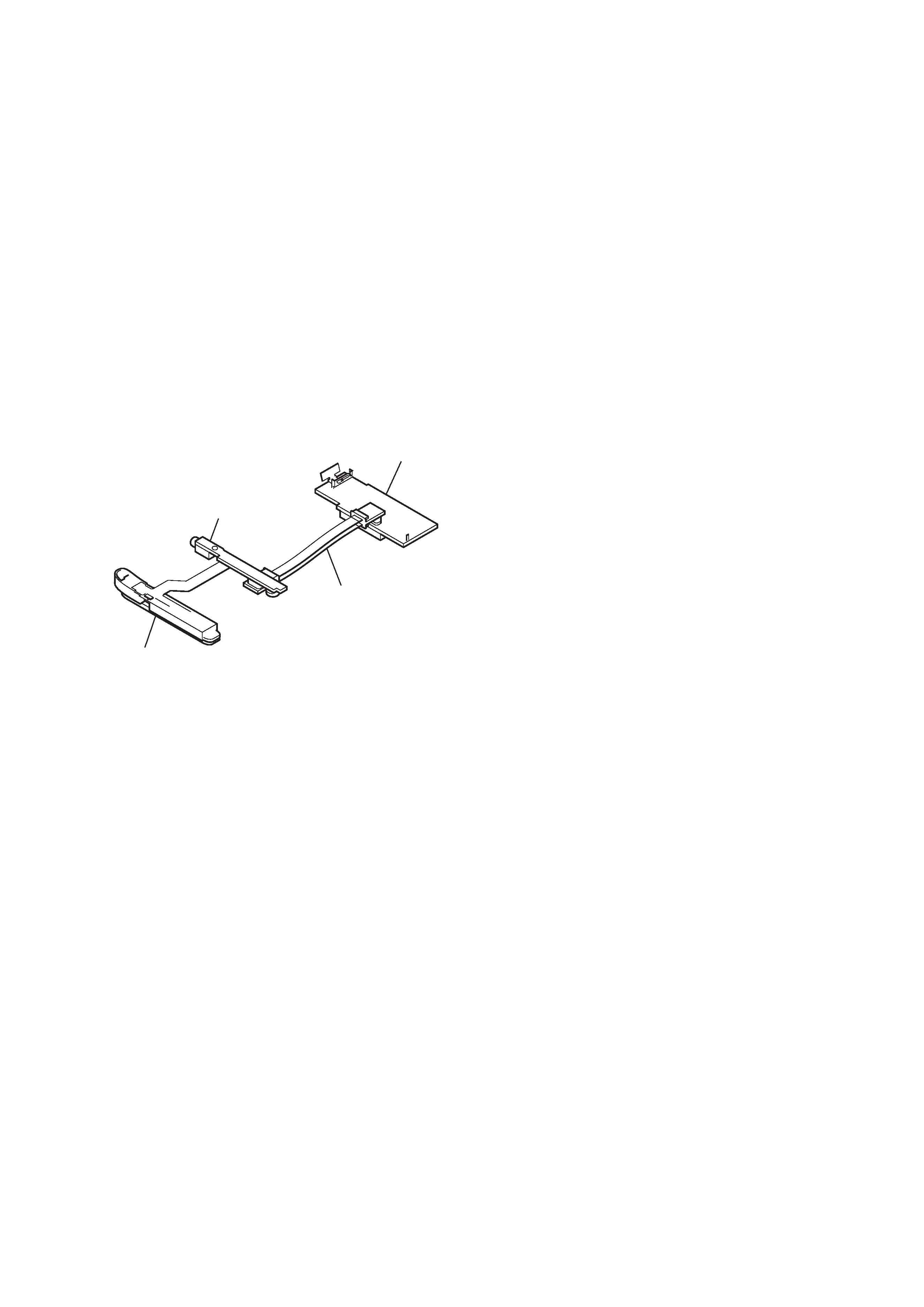
· To check the operation when the MAIN board and SUB board
are removed, check it after connecting CN100 on the MAIN
board and CN200 on the SUB board with the servicing jig (relay
board between the MAIN board and SUB board) as shown below.
SECTION 1
SERVICING NOTES
MAIN board
console unit
SUB board
servicing jig
(MAIN/SUB relay board)
4
NW-MS9
SECTION 2
GENERAL
This section is extracted from
instruction manual.
33
Other
Information
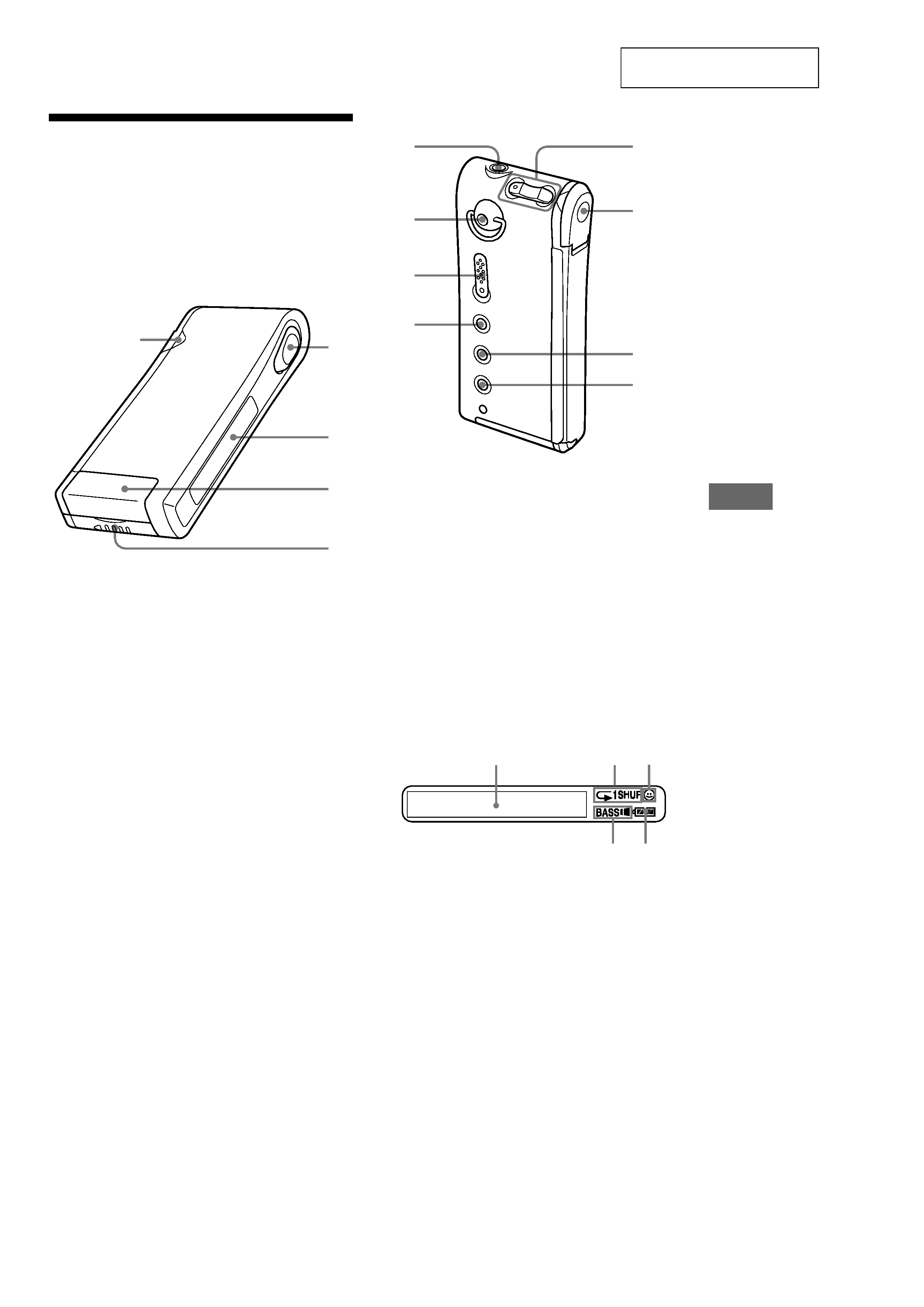
Looking at the
controls
Network Walkman
(front)
1
Access lamp (page 9)
2
Seesaw key (page 11-14, 16-22)
3
Display (page 12, 15)
4
Memory Stick slot (page 9, 11)
5
Battery compartment (page 8)
(rear)
6 i
(Headphones/earphones) jack (page 11)
7
Hole for attaching the key ring or strap
(The strap is not supplied)
8
HOLD switch (page 16)
9
MEGA BASS/AVLS button (page 14)
0
VOLUME +/ buttons (page 11, 16)
qa
Dedicated USB jack (page 9)
qs
MENU button (page 13, 16-22)
qd
DISPLAY button (page 12, 15)
Display
1
Text/graphic information display
(page 15)
2
Playback mode indication (page 13)
3
AVLS indication (page 14)
4
MEGA BASS indication (page 14)
5
Battery remain indication (page 8)
2
1
3
4
5
6
q;
qa
qs
qd
7
8
9
12
3
45
NW-MS9
5
· This set can be disassembled in the order shown below.
3-1.
DISASSEMBLY FLOW
SECTION 3
DISASSEMBLY
Note: Follow the disassembly procedure in the numerical order given.
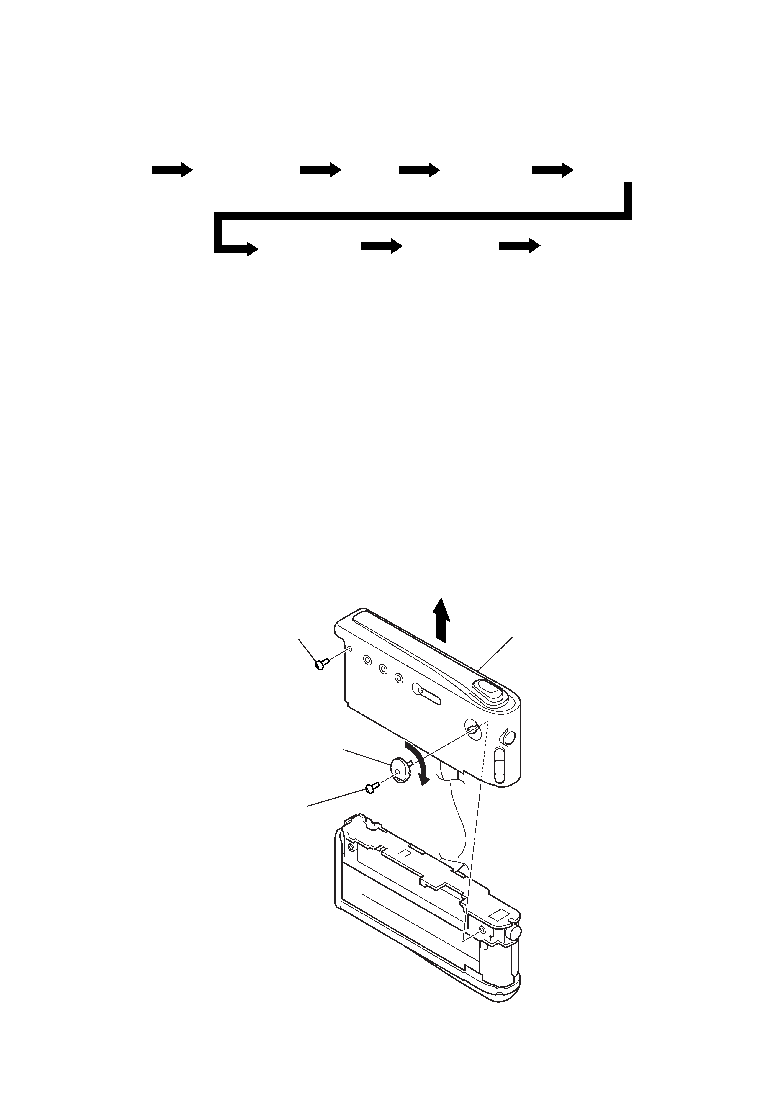
3-2.
CASE BLOCK ASSY
Set
3-2. Case block assy
3-3. Case
3-4. Guide (LED)
3-5. Chassis (main) assy
3-7. Console assy
3-6. "Console unit",
"Sub board"
"Main board"
3-8. Console board
,
1
tapping screw
(M1.4
× 3.5)
3
Remove the strap shaft assy rotating
in the direction of arrow A.
2
tapping screw
(M1.4
× 3.5)
4
case block assy
A