SERVICE MANUAL
PORTABLE MINIDISC RECORDER
Hong Kong Model
Tourist Model
MZ-R910
US and foreign patents licensed from Dolby
Laboratories.
Continued on next page
Model Name Using Similar Mechanism
NEW
Mechanism Type
MT-MZR910-180
Optical Pick-up Name
LCX-5RV
Ver 1.0 2002. 06
9-874-055-01
Sony Corporation
2002F0200-1
Personal Audio Company
C
2002.06
Published by Sony Engineering Corporation
Audio playing system
MiniDisc digital audio system
Laser diode properties
Material:GaAlAs
Wevelength :
=790nm
Emissin duration : continuous
Laser output : less than 44.6 µW
(This output is the value measured at a distance of 200 mm from the
lens surface on the optial pick-up block with 7 mm aperture.)
Recording and playback time (when using MDW-80)
Maximum 160 min. in monaural
Maximum 320 min. in stereo
Revolutions
382 rpm to 2,700 rpm (CLV)
Error correction
ACIRC (Advanced Cross Interleave Reed Solomon Code)
Sampling frequency
44.1 kHz
Sampling rate converter
Input : 32 kHz/44.1 kHz/48 kHz
Coding
ATRAC (Adaptive TRansform Acoustic Coding)
ATRAC3 - LP2/LP4
Modulation system
EFM (Eight to Fourteer Modulation)
Frequency response
20 to 20,000 Hz ± 3 dB
Wow and Flutter
Below measurable limit
Inputs 1)
MIC : sterto mini-jack
(minimum input level 0.25 mV)
Line in :
stereo mini-jack for anolog input (minimum input level 49 mV)
optical (digital) mini-jack for optical (digital) input
Outputs
i
/LINE OUT 2) : stereo mini-jack (dedicated remote control jack) /
194 mv(10 kohm)
Maximum output(DC) 2)
Headphones : 5 mW + 5 mW(16 ohm)
Power requirements
Sony AC Power Adaptor connected at the DC IN 3V jack (country
model in parentheses) :
230 - 240 V AC, 50 Hz (Hong Kong)
100 - 240 V AC, 50/60 Hz (Tourist)
The recorder :
Nickel metal hydride rechargeable battery
NH-14WM(A) 1.2V 1350 mAh (MIN) Ni-MH
LR6 (SG) alkaline battery
Battery charging stand:
AC power adaptor DC 3V
Dimensions
Approx.78.9 x 72.0 x17.1 mm (w/h/d)
(3 1/8 x 2 7/8 x 11/16 in.)
SPECIFICATIONS
2
MZ-R910
CAUTION
Use of controls or adjustments or performance of procedures
other than those specified herein may result in hazardous ra-
diation exposure.
Notes on chip component replacement
· Never reuse a disconnected chip component.
· Notice that the minus side of a tantalum capacitor may be dam-
aged by heat.
Flexible Circuit Board Repairing
· Keep the temperature of the soldering iron around 270 °C dur-
ing repairing.
· Do not touch the soldering iron on the same conductor of the
circuit board (within 3 times).
· Be careful not to apply force on the conductor when soldering
or unsoldering.
UNLEADED SOLDER
Boards requiring use of unleaded solder are printed with the lead-
free mark (LF) indicating the solder contains no lead.
(Caution: Some printed circuit boards may not come printed with
the lead free mark due to their particular size)
: LEAD FREE MARK
Unleaded solder has the following characteristics.
· Unleaded solder melts at a temperature about 40 °C higher than
ordinary solder.
Ordinary soldering irons can be used but the iron tip has to be
applied to the solder joint for a slightly longer time.
Soldering irons using a temperature regulator should be set to
about 350 °C .
Caution: The printed pattern (copper foil) may peel away if the
heated tip is applied for too long, so be careful!
· Strong viscosity
Unleaded solder is more viscous (sticky, less prone to flow) than
ordinary solder so use caution not to let solder bridges occur
such as on IC pins, etc.
· Usable with ordinary solder
It is best to use only unleaded solder but unleaded solder may
also be added to ordinary solder.
SAFETY-RELATED COMPONENT WARNING!!
COMPONENTS IDENTIFIED BY MARK 0 OR DOTTED
LINE WITH MARK 0 ON THE SCHEMATIC DIAGRAMS
AND IN THE PARTS LIST ARE CRITICAL TO SAFE
OPERATION. REPLACE THESE COMPONENTS WITH
SONY PARTS WHOSE PART NUMBERS APPEAR AS
SHOWN IN THIS MANUAL OR IN SUPPLEMENTS PUB-
LISHED BY SONY.
Battery life
When recording
(Unit: approxi.hours)(JEITA1))
Batteries
SP
Stere o
LP2
Stere o
LP4
Stereo
Nickel me ta l
hydride
rechargeable
battery 2)
12
17
21
LR6 (S G)
Sony alkaline
dry battery 3)
12
19
23
Nickel metal
hydride
rechargeable
battery
+ On e LR6
(SG)
30
43
52
1) Measured in accordance with the J EITA (J a pa n
Ele ctronic s a nd Informa tion Technology
Industries Association) standard.
2) Whe n us ing a 100% fully cha rged
nickel
metal hydride rechargeable ba ttery (NH-
14WM(A)).
3) Whe n us ing a S ony LR6 (S G)"STAMINA "
a lka line dry batte ry (produced in Ja pan).
When playing
(Unit
Batteries
S P
Stereo
LP2
Stereo
LP4
Stere o
Nickel metal
hydride
rechargeable
battery2)
30
38
42
LR6 (S G)
Sony alkaline
dry battery 3)
44
52
62
Nickel metal
hydride
rechargeable
battery 2)
+ On e LR6
(SG)3)
79
95
110
1) Measured in accordance woth the J EITA
(Japan Electronics and Information
Technology Industries Association) standard.
2) Whe n us ing a 100% fully charged
nickel
metal hydride rechargeable battery (NH-
14WM(A)).
3) When using a Sony LR6 (S G) "STAMINA "
a lka line dry battery (produced in Ja pan)
: approxi.hours)(JEITA1))
Mass
Approx. 108g (3.8 oz) the recorder only
1) The LINE IN (OPT) jack is used to connect either a digital (optical)
cable or a line (analog) cable.
2) The i/LINE OUT jack connects either headphones/earphones or a
line cable.
Design and specitications are subjext to change without notice.

3
MZ-R910
TABLE OF CONTENTS
1.
SERVICING NOTES ............................................... 4
2.
GENERAL ................................................................... 5
3.
DISASSEMBLY
3-1. Disassembly Flow ...........................................................
6
3-2. Panel Assy, Bottom .........................................................
6
3-3. Panel Assy, Upper Section ..............................................
7
3-4. "LCD Module", "Panel Assy,Upper" .............................
7
3-5. MAIN Board Assy ..........................................................
8
3-6. "Case Assy, Battery", "MAIN Board" ...........................
8
3-7. Strip, Ornamental ............................................................
9
3-8. "MD Mechanism Desk (MT-MZR910-180)",
"Chassis Assy, Set" .........................................................
9
3-9. Service Assy, OP (LCX-5RV) ......................................... 10
3-10. Holder Assy ..................................................................... 10
3-11. Motor, DC (Sled) (M602) ............................................... 11
3-12. "Motor, DC (Spindle) (M601)",
"Motor, DC (Over Write Head UP/DOWN) (M603)" ... 12
4.
TEST MODE .............................................................. 13
5.
ELECTRICAL ADJUSTMENTS ......................... 19
6.
DIAGRAMS
6-1. Note for Printed Wiring Board and
Schematic Diagrams ....................................................... 44
6-2. Block Diagram SERVO Section ............................... 46
6-3. Block Diagram AUDIO Section ............................... 47
6-4. Block Diagram DISPLAY/KEY CONTROL/
POWER SUPPLY Section ........................................... 48
6-5. Printed Wiring Board
MAIN Board (Component Side) ............................. 49
6-6. Printed Wiring Board
MAIN Board (Conductor Side) ............................... 50
6-7. Schematic Diagram MAIN Board (1/4) .................. 51
6-8. Schematic Diagram MAIN Board (2/4) .................. 52
6-9. Schematic Diagram MAIN Board (3/4) .................. 53
6-10. Schematic Diagram MAIN Board (4/4) .................. 54
6-11. IC Pin Function Description ........................................... 60
7.
EXPLODED VIEWS
7-1. Panel Section ................................................................... 67
7-2. Chassis Section ............................................................... 68
7-3. MD Mechanism Deck Section (MT-MZR910-180) ....... 69
8.
ELECTRICAL PARTS LIST ............................... 70
4
MZ-R910
NOTES ON HANDLING THE OPTICAL PICK-UP
BLOCK OR BASE UNIT
The laser diode in the optical pick-up block may suffer electro-
static break-down because of the potential difference generated
by the charged electrostatic load, etc. on clothing and the human
body.
During repair, pay attention to electrostatic break-down and also
use the procedure in the printed matter which is included in the
repair parts.
The flexible board is easily damaged and should be handled with
care.
NOTES ON LASER DIODE EMISSION CHECK
Never look into the laser diode emission from right above when
checking it for adjustment. It is feared that you will lose your sight.
NOTES ON HANDLING THE OPTICAL PICK-UP BLOCK
(LCX-5RV)
The laser diode in the optical pick-up block may suffer electro-
static break-down easily. When handling it, perform soldering
bridge to the laser-tap on the flexible board. Also perform mea-
sures against electrostatic break-down sufficiently before the op-
eration. The flexible board is easily damaged and should be handled
with care.
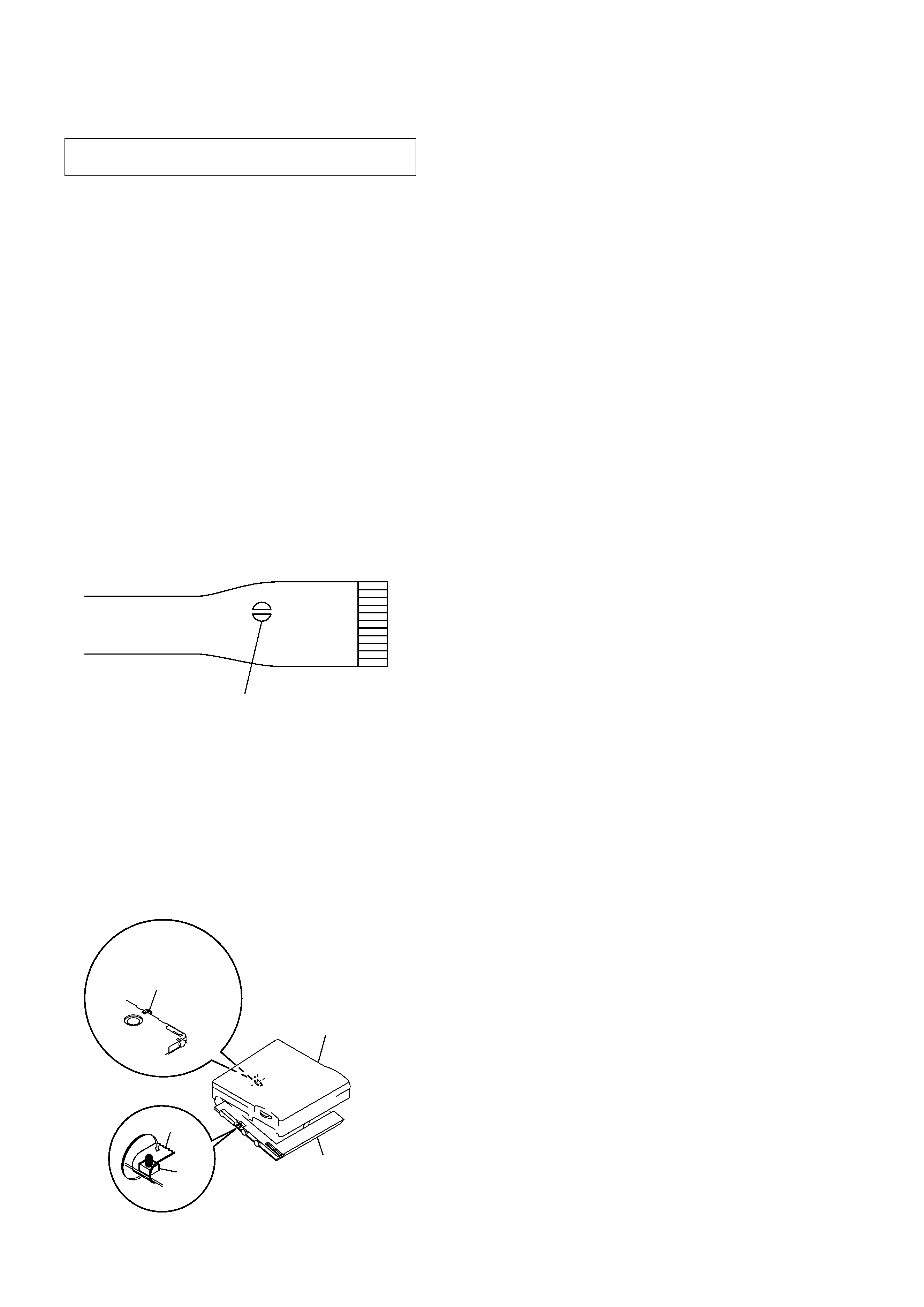
OPTICAL PICK-UP FLEXIBLE BOARD
SECTION 1
SERVICING NOTES
· In performing the repair with the power supplied to the set, re-
moving the MAIN board causes the set to be disabled.
In such a case, fix a convex part of the open/close detect switch
(S804 on MAIN board) with a tape in advance.
Handle the FLEXIBLE board (over write head) with care, as it
has been soldered directly to the MAIN board.
In repairing the component side of MAIN board, connect the
FLEXIBLE board (over write head) and the MAIN board with
the lead wires in advance. (See page 8)
laser-tap
upper panel assy
MAIN board
Tape
S804
FLEXIBLE board
(Over write head)
· The shipment data will be cleared when the NV is reset. There-
fore, change the NV adjusted values following the Change of
NV Adjusted Values immediately after the NV was reset. (See
page 19)
· This set requires the patch data in the nonvolatile memory
(IC802) to be rewritten using the application, when the MAIN
board or nonvolatile memory (IC802) was replaced. (See page
26)
· Replacement of CXD2677-204GA (IC801) uesd in this set re-
quires a special tool.
5
MZ-R910
SECTION 2
GENERAL
This section is extracted from
instruction manual.
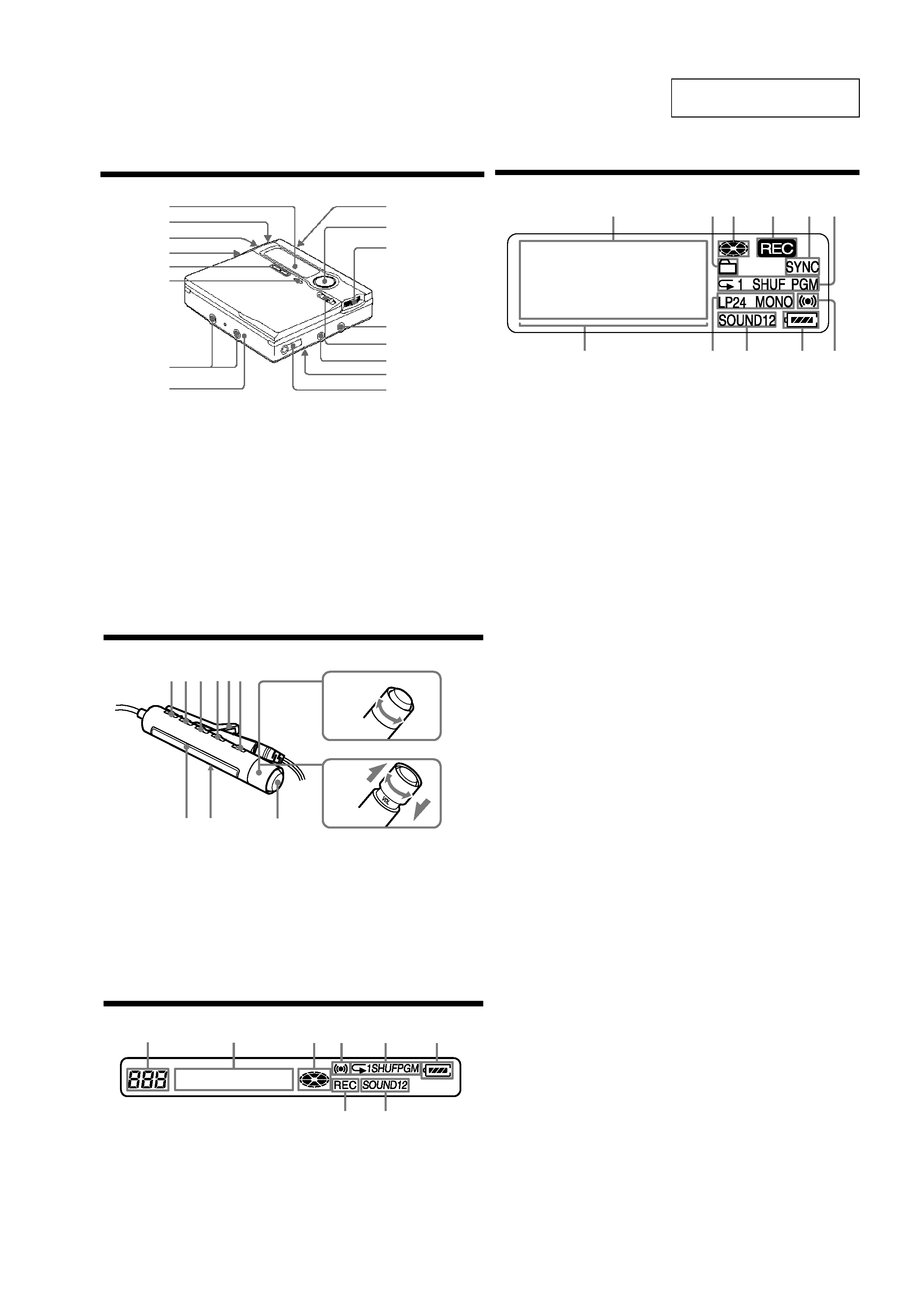
The display window of the recorder
1 Character information display
Displays the disc and track names,
date, error messages, track numbers,
etc.
2 Group intication
3 Disc intication
Shows that the disc is rotating for
recording, playing or editing an MD.
4 REC intication
Lights up while recording.When
flashing, the recorder is in record
standby mode.
5 SYNC (synchro-recording) intication
6 Play mode intication
Shows the play mode (shuffle play,
program play, repeat play, etc.) of
the MD
7 Level meter
8 LP2 (LP2 stereo), LP4 (LP4 stereo),
MONO (LP4 stereo)
9 Sound intication
Lights up when Digital Sound Preset
is on.
0 Battery intication
Shows approximatevbattery condition.
qa Melody timer intication
1
4
3
2
5
qa
9
q;
8
7
6
The headphones/earphones with a remote control
1 DISPLAY button
2 PLAY MODE button
3 RPT/ENT (repeat/enter) button
4 SOUND button
5 Clip
6
X (pause) button
7 Control (./N>)
N> : play, AMS, FF
. : REW
Turn or turn and hold to play, fast
forward or rewind.
You can quickly fast forward or
rewind without listening to the
play back sound.
8
Control (VOLUME +/-)
Pull and turn to adjust the volume.
9 Display window
0 HOLD switch
qa x
(stop) button
May be used as the Enter button,
depending on the function.
The display window of the remote control
1 Trak number display
2 Character information display
3 Disc indication
4 Melody timer indication
5 Play mode indication
6 Battery leavl indication
7 REC indication
8 SOUND indication
6
8
7
1
2
4
5
3
+
--
1 23 45
qa
6
9
7
8
0
Looking at controls
The recorder
1 Display window
2 T MARK button
3 Battery compartment
4 END SERCH button
5 VOLUME + */- buttons
* The VOLUME + button has a tactile dot.
6 Terminals for attaching dry battery case
7 DC IN 3V jack
8 GROUP / CANCEL buttons
9 OPEN buttons
0
1
2
3
4
5
6
7
8
9
0
5-way control key
· For basic operations
Press N* to play / enter.
* the N buttons has a tactile dot.
Press ./ > to rewind / fast forward.
Press X to pause.
Press CHG x to stop / charge.
qh i / LINE OUT jack
qa
Jog dial (MENU / ENTER)
Press to enter the menu, turn to select,
and then press to enter.
qs LINE IN (OPT) jack
qd MIC (PLUG IN POWER)* jack
* There is a tactile dot beside the MIC
(PLUG IN POWER) jack
qf REC (record) switch
qg
qh
qa
qs
qd
qf
qg
Hold switch (at the rear)
· For moving the cursor and entering
selected items (during text entry and
other settings).