SERVICE MANUAL
MICROFILM
PORTABLE MINIDISC RECORDER
MZ-R30
US Model
Canadian Model
AEP Model
UK Model
E Model
Australian Model
Tourist Model
Model Name Using Similar Mechanism
NEW
MD Mechanism Type
MT-MZR30-124
Optical Pick-up Type
KMS-250A/J2N
US and foreign patents licensed from Dolby
Laboratories Licensing Corporation.
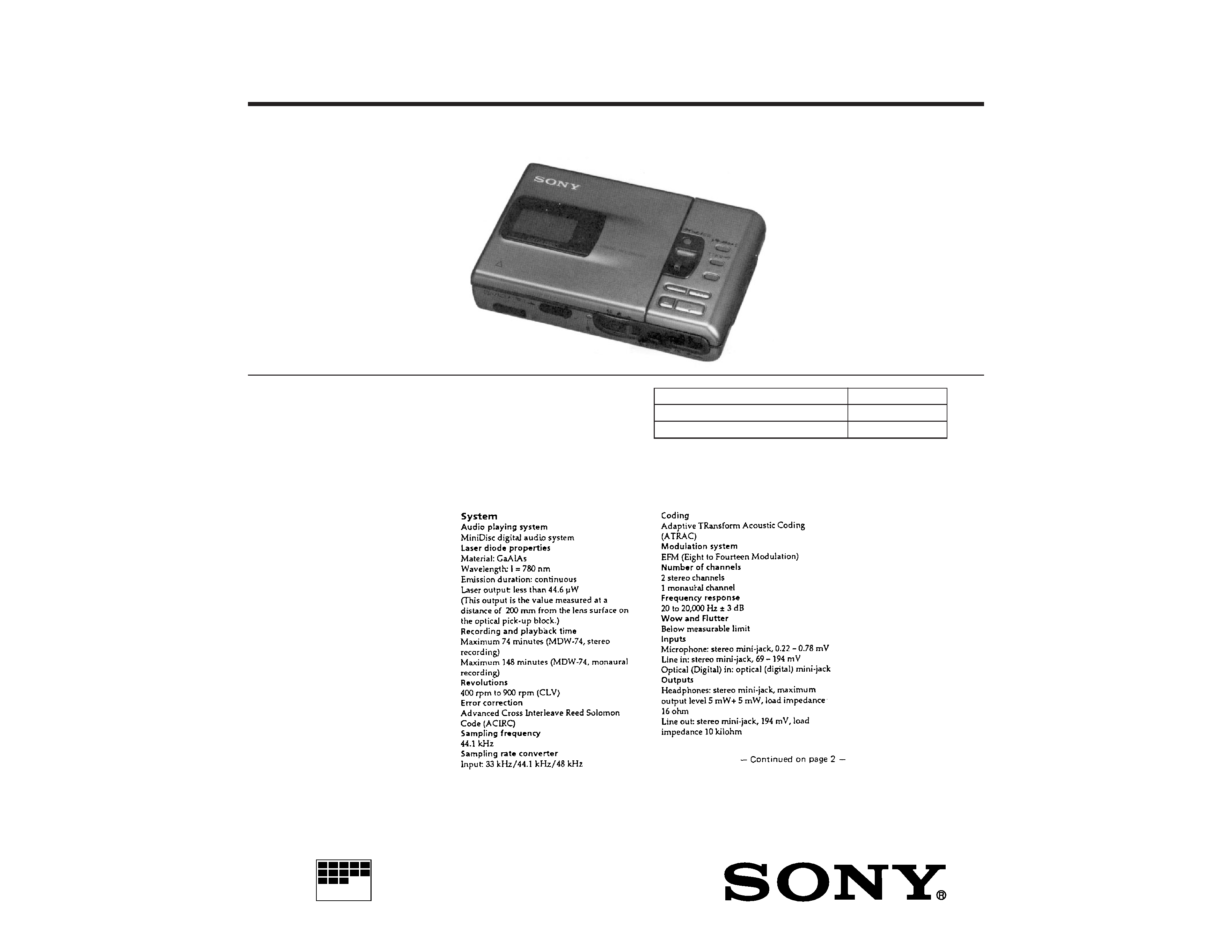
SPECIFICATIONS
2
TABLE OF CONTENTS
Specifications ............................................................................... 1
1.
SERVICE NOTE .................................................................. 3
2.
GENERAL ............................................................................ 4
3.
DISASSEMBLY
3-1. Upper Panel Assy, Bottom Panel Assy Removal .......... 20
3-2. Main Board Removal ................................................... 20
3-3. Mechanism Deck Removal ........................................... 21
3-4. Optical Pick-up Assy, Control Board,
REC Board Removal .................................................... 21
3-5. Battery Case Assy Removal ......................................... 22
3-6. Switch board, Power Board Removal ........................... 22
4.
TEST MODE ...................................................................... 23
5.
ELECTRICAL ADJUSTMENTS ..................................... 29
6.
EXPLANATION OF IC TERMINALS ............................. 33
7.
DIAGRAMS
7-1. Block Diagram .............................................................. 37
7-2. Cricuit Boards Location ............................................... 41
7-3. Printed Wiring Boards Main Section ...................... 42
7-4. Schematic Diagram Main (1/3) Section ................. 47
7-5. Schematic Diagram Main (2/3) Section ................. 51
7-6. Schematic Diagram Main (3/3) Section ................. 55
7-7. Schematic Diagram Power Section ....................... 57
7-8. Printed Wiring Boards Control Section .................. 60
7-9. Schematic Diagram Control Section ..................... 63
8.
EXPLODED VIEWS
8-1. Upper Panel, Bottom Panel Section ............................. 69
8-2. Chassis Section ............................................................. 70
8-3. Mechanism Deck Section-1 .......................................... 71
8-4. Mechanism Deck Section-2 .......................................... 72
9.
ELECTRICAL PARTS LIST ............................................ 73
Flexible Circuit Board Repairing
· Keep the temperature of the soldering iron around 270
°C during
repairing.
· Do not touch the soldering iron on the same conductor of the cir-
cuit board (within 3 times).
· Be careful not to apply force on the conductor when soldering or
unsoldering.
Notes on chip component replacement
· Never reuse a disconnected chip component.
· Notice that the minus side of a tantalum capacitor may be dam-
aged by heat.
ATTENTION AU COMPOSANT AYANT RAPPORT
À LA SÉCURITÉ!
LES COMPOSANTS IDENTIFIÉS PAR UNE MARQUE
! SUR LES
DIAGRAMMES SCHÉMATIQUES ET LA LISTE DES PIÈCES SONT
CRITIQUES POUR LA SÉCURITÉ DE FONCTIONNEMENT. NE
REMPLACER CES COMPOSANTS QUE PAR DES PIÈCES SONY
DONT LES NUMÉROS SONT DONNÉS DANS CE MANUEL OU
DANS LES SUPPLÉMENTS PUBLIÉS PAR SONY
SAFETY-RELATED COMPONENT WARNING!!
COMPONENTS IDENTIFIED BY MARK
! OR DOTTED LINE WITH
MARK
! ON THE SCHEMATIC DIAGRAMS AND IN THE PARTS
LIST ARE CRITICAL TO SAFE OPERATION.
REPLACE THESE COMPONENTS WITH SONY PARTS WHOSE
PART NUMBERS APPEAR AS SHOWN IN THIS MANUAL OR IN
SUPPLEMENTS PUBLISHED BY SONY.
CAUTION
Use of controls or adjustments or performance of procedures other
than those specified herein may result in hazardous radiation expo-
sure.
IN NO EVENT SHALL SELLER BE
LIABLE FOR ANY DIRECT,
INCIDENTAL OR CONSEQUENTIAL
DAMAGES OF ANY NATURE, OR
LOSSES OR EXPENSES RESULTING
FROM ANY DEFECTIVE PRODUCT
OR THE USE OF ANY PRODUCT.
"MD WALKMAN" is a trademark of Sony
Corporation.
This MiniDisc Recorder is classified as a
CLASS 1 LASER product.
The CLASS 1 LASER PRODUCT label is
located on the buttom exterior.
For customers in Europe
3
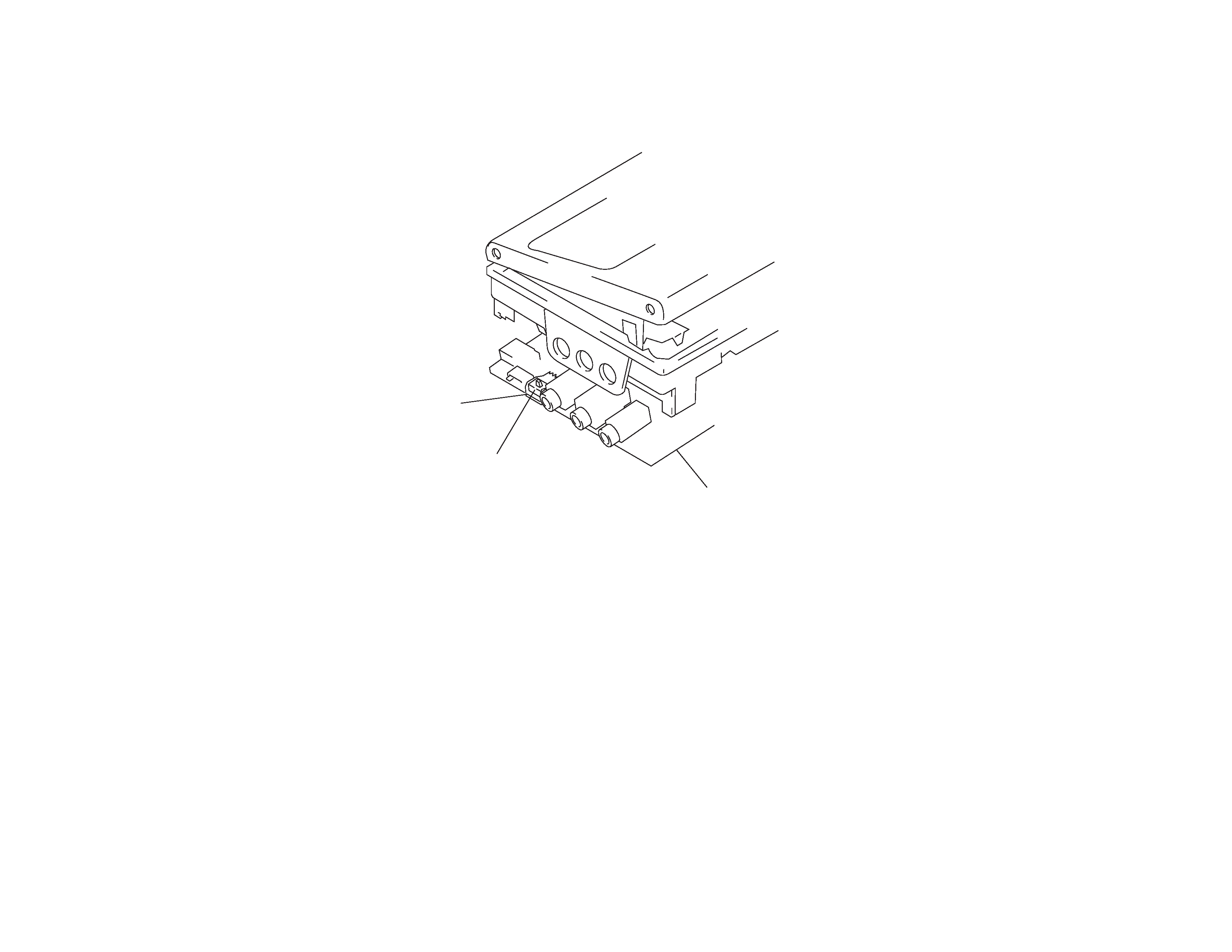
When repairing this device with the power on, if you remove the main board or open the upper panel assembly, this device stops working.
In this case, you can work without the device stopping by fastening the hook of the Open/Close detection switch (S817) with tape.
Door open/close
switch (S817)
Tape
Main board
SECTION 1
SERVICING NOTE
4
SECTION 2
GENERAL
This section is extracted from
instruction manual.
5