SERVICE MANUAL
PORTABLE MINIDISC RECORDER
AEP Model
UK Model
E Model
Australian Model
Chinese Model
Tourist Model
SPECIFICATIONS
MZ-N710
US and foreign patents licensed from Dolby
Laboratories.
Continued on next page
Model Name Using Similar Mechanism
MZ-R410
Mechanism Type
MT-MZN710-177
Optical Pick-up Name
LCX-5R
Ver 1.3 2003. 09
9-874-278-04
Sony Corporation
2003I16-1
Personal Audio Company
C
2003.9
Published by Sony Engineering Corporation
· SonicStage, OpenMG and the OpenMG
logo, MagicGate, Memory Stick and the
MagicGate Memory Stick logo,
Memory Stick and the Memory Stick
logo, Net MD and the Net MD logo are
trademarks of Sony Corporation.
· Microsoft, Windows, Windows NT and
Windows Media are trademarks or
registered trademarks of Microsoft
Corporation in the United States and /or
other countries.
· IBM and PC/AT are registered
trademarks of International Business
Machines Corporation.
· Macintosh is a trademark of Apple
Computer, Inc. in the United States and/
or other countries.
· MMX and Pentium are trademarks or
registered trademarks of Intel
Corporation.
Audio playing system
MiniDisc digital audio system
Laser diode properties
Material: GaAlAs
Wavelength:
= 790 nm
Emission duration: continuous
Laser output: less than 44.6
µW
(This output is the value measured at a distance
of 200 mm from the lens surface on the optical
pick-up block with 7 mm aperture.)
Recording and playback time (when
using MDW-80)
Maximum 160 min. in monaural
Maximum 320 min. in LP4 stereo
Revolutions
380 rpm to 2,700 rpm (CLV)
Error correction
ACIRC (Advanced Cross Interleave Reed
Solomon Code)
Sampling frequency
44.1 kHz
Sampling rate converter
Input: 32 kHz/44.1 kHz/48 kHz
Coding
ATRAC (Adaptive TRansform Acoustic
Coding)
ATRAC3 -- LP2/LP4
2
MZ-N710
Modulation system
EFM (Eight to Fourteen Modulation)
Frequency response
20 to 20,000 Hz
± 3 dB
Inputs1)
MIC: stereo mini-jack
(minimum input level 0.12 mV)
Line in:
stereo mini-jack for analog input
(minimum input level 49 mV)
optical (digital) mini-jack for optical
(digital) input
Outputs
i: stereo mini-jack
Maximum output level
1.2 mW + 1.2 mW; load impedance
16
(European models)
5 mW + 5 mW; load impedance
16
(Other models)
The recorder:
Nickel metal hydride rechargeable battery
NH-10WM 1.2V 900 mAh (MIN) Ni-MH
LR6 (size AA) alkaline battery
Battery charging stand:
AC power adaptor DC 3V
Dimensions
Approx. 81.0
× 74.4 × 20.0 mm (w/h/d)
(31/4
× 3 × 13/16 in.)
Mas
Supplied accessories
s
Approx. 108 g (3.8 oz) the recorder only
1)The LINE IN (OPTICAL) jack is used to
connect either a digital (optical) cable or a line
(analog) cable.
2)The i jack connects either headphones/
earphones or a line cable.
3)Measured in accordance with JEITA.
US and foreign patents licensed from Dolby
Laboratories.
Design and specifications are subject to change
without notice.
Optical cable (1)
CD-ROM (SonicStage Ver. 1.5) (1)*
Carrying pouch or carrying case with a belt clip (1)
Do
Design and apecifications are subject to change
without notice.
not play a CD-ROM on an audio CD play
AC power adaptor (1)
Battery charging stand (1)
Headphones/earphones with
a remote control (1)
NH-10WM Nickel metal
hydride rechargeable
battery (1)
Dedicated USB cable (1)
Battery carrying case (1)
Dry battery case (1)
When to replace the batteries
When the dry battery or rechargeable
battery is weak, flashing r or "LOW
BATT" appears in the display. Replace the
dry battery or charge the rechargeable
battery.
The battery level indicator is approximate.
It may be more or less than the indication
depending on the operating condition.
Note
Stop the recorder before replacing battery.
Battery life
The battery life may be shorter due to
operating conditions, the temperature of
the location, or alkaline dry battery you
use.
When recording
(Unit: approx.hours)(JEITA1))
1) Measured in accordance with the JEITA (Japan
Electronics and Information Technology
Industries Association) standard.
Batteries
SP
Stereo
LP2
Stereo
LP4
Stereo
Nickel metal
hydride
rechargeable
battery2)
2) When using a 100% fully charged nickel metal
hydride rechargeable battery (NH-10WM).
7.5
9.5
13
LR6 Sony
alkaline dry
battery3)
3) When using a Sony LR6 (SG) "STAMINA"
alkaline dry battery (produced in Japan).
12.5
16
19
Nickel metal
hydride
rechargeable
battery
+ One LR6
26
34
41
When playing
(Unit: approx.hours)(JEITA)
Batteries
SP
Stereo
LP2
Stereo
LP4
Stereo
Nickel metal
hydride
rechargeable
battery
19.5
23
27
LR6 Sony
alkaline dry
battery
42
48
56
Nickel metal
hydride
rechargeable
battery
+ One LR6
63
70
85
Power requirements
Sony AC Power Adaptor connected at the DC
IN 3V jack:
120 V AC, 60 Hz (Models for Mexico,
Taiwan)
230 V AC, 50/60 Hz (Models for continental
Europe, Singapore and Thailand)
240 V AC, 50 Hz (Model for Australia)
220 V AC, 50 Hz (Model for China)
230 - 240 V AC, 50 Hz (Models for U.K. and
Hong Kong)
220 V AC, 50 Hz (Model for Argentine)
100 - 240 V AC, 50/60 Hz (Other models)
and
SAFETY-RELATED COMPONENT WARNING!!
COMPONENTS IDENTIFIED BY MARK 0 OR DOTTED LINE
WITH MARK 0 ON THE SCHEMATIC DIAGRAMS AND IN
THE PARTS LIST ARE CRITICAL TO SAFE OPERATION.
REPLACE THESE COMPONENTS WITH SONY PARTS WHOSE
PART NUMBERS APPEAR AS SHOWN IN THIS MANUAL
OR IN SUPPLEMENTS PUBLISHED BY SONY.
Ver 1.1 2003.02
3
MZ-N710
TABLE OF CONTENTS
1.
SERVICING NOTES ............................................... 4
2.
GENERAL ................................................................... 5
3.
DISASSEMBLY
3-1. Disassembly Flow ...........................................................
6
3-2. Case (Lower) ...................................................................
7
3-3. MAIN Board, Battery Case ............................................
7
3-4. Panel (Upper) Section .....................................................
8
3-5. LCD Module, Panel Upper Block ..................................
8
3-6. Mechanism Deck (MT-MZN710-177) ...........................
9
3-7. OP Service Assy (LCX-5R) ............................................ 10
3-8. Holder Assy ..................................................................... 11
3-9. DC Motor (Sled) (M602) ................................................ 11
3-10. DC Motor (Over Write Head Up/Down) (M603),
DC SSM18B Motor (Spindle) (M601) ........................... 12
4.
TEST MODE .............................................................. 13
5.
ELECTRICAL ADJUSTMENTS ......................... 18
6.
DIAGRAMS
6-1. Block Diagram ................................................................ 37
6-2. Note for Printed Wiring Board and
Schematic Diagrams ....................................................... 38
6-3. Printed Wiring Board
MAIN Board (Side A) ............................................. 39
6-4. Printed Wiring Board
MAIN Board (Side B) ............................................. 40
6-5. Schematic Diagram MAIN Board (1/4) .................. 41
6-6. Schematic Diagram MAIN Board (2/4) .................. 42
6-7. Schematic Diagram MAIN Board (3/4) .................. 43
6-8. Schematic Diagram MAIN Board (4/4) .................. 44
6-9. IC Pin Function Description ........................................... 50
7.
EXPLODED VIEWS
7-1. Case Section .................................................................... 56
7-2. Chassis Section ............................................................... 57
7-3. MAIN Board Section ...................................................... 58
7-4. Mechanism Deck Section-1 (MT-MZN710-177) ........... 59
7-5. Mechanism Deck Section-2 (MT-MZN710-177) ........... 60
8.
ELECTRICAL PARTS LIST ............................... 61
CAUTION
Use of controls or adjustments or performance of procedures
other than those specified herein may result in hazardous ra-
diation exposure.
Notes on chip component replacement
· Never reuse a disconnected chip component.
· Notice that the minus side of a tantalum capacitor may be dam-
aged by heat.
Flexible Circuit Board Repairing
· Keep the temperature of the soldering iron around 270 °C dur-
ing repairing.
· Do not touch the soldering iron on the same conductor of the
circuit board (within 3 times).
· Be careful not to apply force on the conductor when soldering
or unsoldering.
UNLEADED SOLDER
Boards requiring use of unleaded solder are printed with the lead-
free mark (LF) indicating the solder contains no lead.
(Caution: Some printed circuit boards may not come printed with
the lead free mark due to their particular size)
: LEAD FREE MARK
Unleaded solder has the following characteristics.
· Unleaded solder melts at a temperature about 40 °C higher than
ordinary solder.
Ordinary soldering irons can be used but the iron tip has to be
applied to the solder joint for a slightly longer time.
Soldering irons using a temperature regulator should be set to
about 350 °C .
Caution: The printed pattern (copper foil) may peel away if the
heated tip is applied for too long, so be careful!
· Strong viscosity
Unleaded solder is more viscous (sticky, less prone to flow) than
ordinary solder so use caution not to let solder bridges occur
such as on IC pins, etc.
· Usable with ordinary solder
It is best to use only unleaded solder but unleaded solder may
also be added to ordinary solder.
On power sources
· Use house current, nickel metal hydride
rechargeable battery, LR6 (size AA) battery,
or car battery.
· For use in your house: For the supplied battery
charging stand, use the AC power adaptor
supplied with this recorder. Do not use any other
AC power adaptor since it may cause the recorder
to malfunction.
· Connect the AC power adaptor to an easily
accessible AC outlet. Should you notice an
abnormality in the AC power adaptor,
disconnect it from the AC outlet immediately.
· The recorder is not disconnected from the AC
power source (mains) as long as it is
connected to the wall outlet, even if the
recorder itself has been turned off.
· If you are not going to use this recorder for a
long time, be sure to disconnect the power
supply (AC power adaptor, dry battery,
rechargeable battery, or car battery cord). To
remove the AC power adaptor from the wall
outlet, grasp the adaptor plug itself; never pull
the cord.
Polarity of the
plug
4
MZ-N710
NOTES ON HANDLING THE OPTICAL PICK-UP
BLOCK OR BASE UNIT
The laser diode in the optical pick-up block may suffer electro-
static break-down because of the potential difference generated
by the charged electrostatic load, etc. on clothing and the human
body.
During repair, pay attention to electrostatic break-down and also
use the procedure in the printed matter which is included in the
repair parts.
The flexible board is easily damaged and should be handled with
care.
NOTES ON LASER DIODE EMISSION CHECK
Never look into the laser diode emission from right above when
checking it for adjustment. It is feared that you will lose your sight.
NOTES ON HANDLING THE OPTICAL PICK-UP BLOCK
(LCX-5R)
The laser diode in the optical pick-up block may suffer electro-
static break-down easily. When handling it, perform soldering
bridge to the laser-tap on the flexible board. Also perform mea-
sures against electrostatic break-down sufficiently before the op-
eration. The flexible board is easily damaged and should be handled
with care.
OPTICAL PICK-UP FLEXIBLE BOARD
SECTION 1
SERVICING NOTES
laser-tap
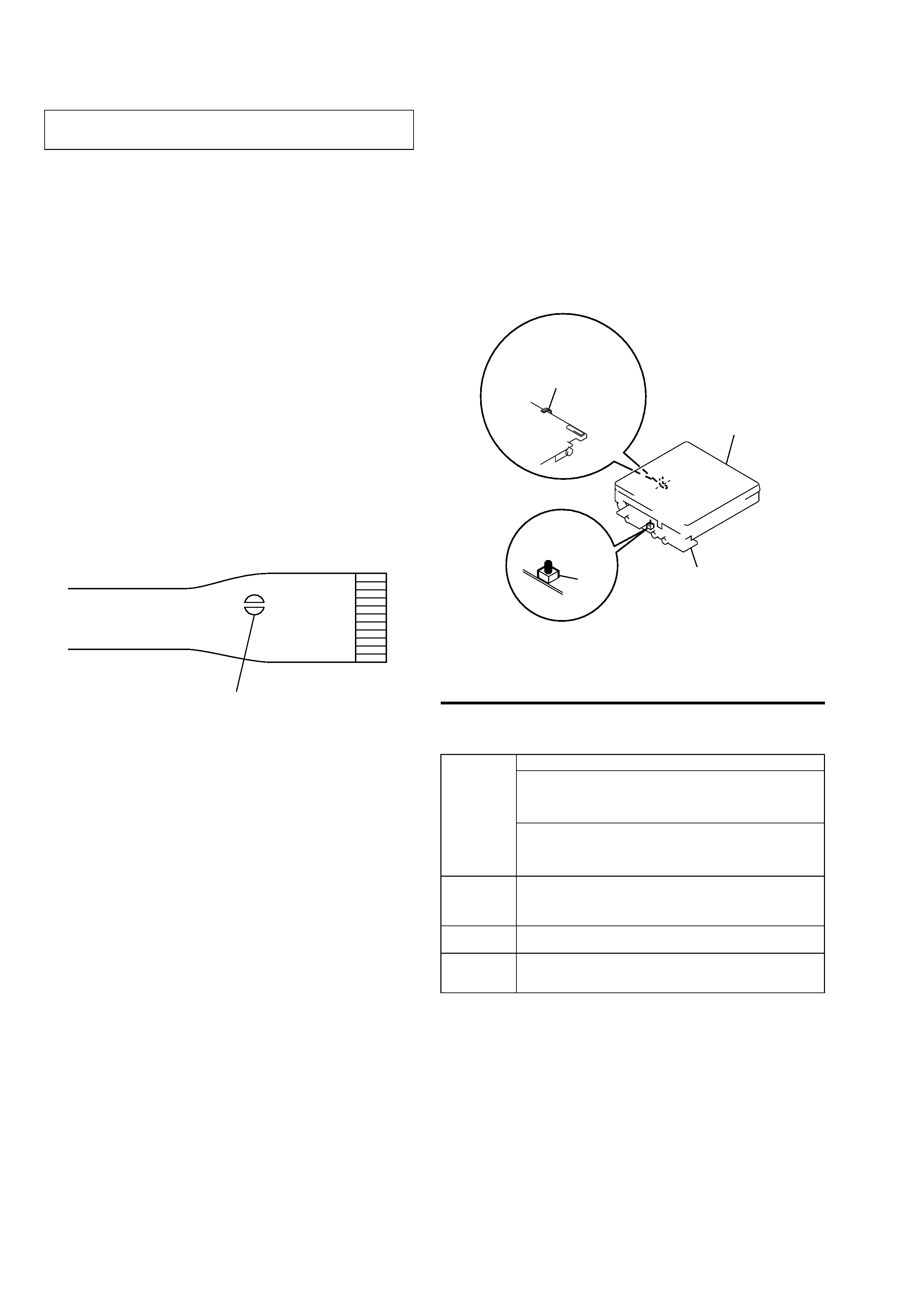
· In performing the repair with the power supplied to the set, re-
moving the MAIN board causes the set to be disabled.
In such a case, fix a convex part of the open/close detect switch
(S803 on MAIN board).
Handle the FLEXIBLE board (over write head) with care, as it
has been soldered directly to the MAIN board.
In repairing the component side of MAIN board, connect the
FLEXIBLE board (over write head) and the MAIN board with
the lead wires in advance.
upper panel assy
MAIN board
S803
FLEXIBLE board
(over write head)
·This set requires the patch data in the nonvolatile memory
(IC851) to be rewritten using the application, when the MAIN
board was replaced. (See page 28)
System requirements
The following hardware and software are required in order to use the SonicStage software
for the Net MD.
This software is not supported by the following environments:
· Macintosh
· Windows XP versions other than Home Edition or Professional
· Windows 2000 versions other than Professional
· Windows 98 versions other than Second Edition
· Windows NT
· Windows 95
· Personally constructed PCs or operating systems
· An environment that is an upgrade of the original manufacturer-installed operating system
· Multi-boot environment
· Multi-monitor environment
Notes
· We do not ensure trouble-free operation on all computers that satisfy the system requirements.
· We do not ensure trouble-free operation of the system suspend, sleep, or hibernation function on all
computers.
Computer
IBM PC/AT or Compatible
CPU: Pentium II 400 MHz or higher (Pentium III 450 MHz or higher
is recommended.)
Hard disk drive space1): 120 MB or more
RAM: 64 MB or higher (128 MB or higher is recommended)
1)
Others
CD-ROM drive (capable of digital playback by WDM)
Sound Board
USB port (supports USB 2.0 Full Speed (previously USB 1.1))
Operating
System
Factory installed:
Windows XP Home Edition/Windows XP Professional/Windows
Millennium Edition/Windows 2000 Professional/Windows 98 Second
Edition
Display
High Color (16bit) or greater, 800
480 dots or more (800 600 dots
or more is recommended)
Others
Internet access: for Web registration and EMD services
Windows Media Player (version 7.0 or higher) installed for playing
WMA files
Note on hard disk drive space
120 MB or more free space on the hard disk drive is required. If your computer does not
have enough space, the software will not be properly installed. The required free space
differs according to the version of your Windows OS, or the amount of audio files that you
handle.
Ver 1.2 2003.06
5
MZ-N710
SECTION 2
GENERAL
This section is extracted from
instruction manual.
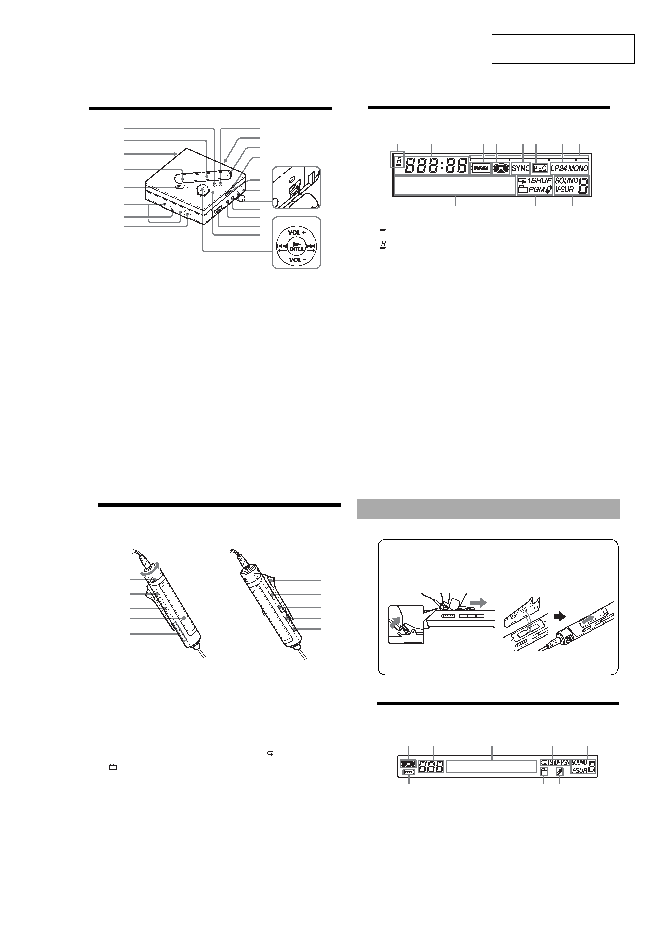
12
Looking at controls
The recorder
A x · CANCEL/CHG button
B Display window
C Battery compartment
D GROUP button
E REC (record) switch
F Terminals for attaching dry battery
case
G Terminals for attaching the battery
charging stand
H DC IN 3V jack
I X button
J OPEN switch
K END SEARCH button
L T MARK button
M HOLD switch
To prevent the buttons from being
accidentally operated when you carry
the recorder, use this function.
N Handstrap hole
Use the hole to attach your own strap.
O USB connecting jack
P LINE IN (OPTICAL) jack
Q MIC (PLUG IN POWER) jack
There is a tactile dot beside the MIC
(PLUG IN POWER) jack.
R i (headphones/earphones)
S MENU button
T 5-position control key
N* · ENTER
. · T
> · t
VOL +*,
*
N and VOL + have a tactile dot.
2
1
4
w;
qg
3
5
6
7
9
qa
qs
qd
qh
qj
qk
ql
qf
q;
8
13
The display window of the recorder
A
: Indication for remaining playing
time of the current track or of the disc
: Indication for remaining
recordable time of the disc
B Time display
C Battery indication
Shows approximate battery condition.
D Disc indication
Shows that the disc is rotating for
recording, playing or editing an MD.
E SYNC (synchro-recording) indication
F REC indication
Lights up while recording. When
flashing, the recorder is in record
standby mode.
G LP2 (LP2 stereo), LP4 (LP4 stereo),
MONO (monaural) indication
H Level meter
I Character information display
Displays the disc and track names,
date, error messages, track numbers,
etc.
J Play mode indications
Shows the play mode (shuffle play,
program play, repeat play, etc.) of the
MD.
K Sound indications
2
13
4
5
6
7
8
9q;
qa
14
The headphones/earphones with a remote control
A Volume Control (VOL+, )
Turn to adjust the volume.
B x (stop) button
C Jog lever (. · NX/ENT · >)
NX/ENT (to press): play, pause,
enter
.(to slide towards): REW
> (to slide towards): FF
D Display window
E
(group) +,
F Clip
See "Using the clip for the remote
control" (page 15).
G HOLD switch
To prevent the buttons from being
accidentally operated when you carry
the recorder, use this function.
H DISPLAY button
I P MODE/
button
J SOUND button
F
G
H
I
J
B
C
D
E
A
15
The display window of the remote control
A Disc indication
B Track number display
C Character information display
D Play mode indication
E SOUND indication
F Battery level indication
G Group indication
H Bookmark indication
1
2
Using the clip for the remote control
Remove the clip.
Attaching the clip in the opposite
direction.
The clip can be removed and reattached in the opposite direction.
F
G
8
B
AC
D
E