MZ-E909
SERVICE MANUAL
PORTABLE MINIDISC PLAYER
SPECIFICATIONS
US Model
AEP Model
E Model
Tourist Model
Model Name Using Similar Mechanism
NEW
MD Mechanism Type
MT-MZE909-173
Optical Pick-up Mechanism Type
LCX-4E
US and foreign patents licensed from Dolby
Laboratories Licensing Corporation
Ver 1.3 2002.06
with SUPPLEMENT-1
Audio playing system
MiniDisc digital audio system
Laser diode properties
Material: GaAlAs
Wavelength:
= 790 nm
Emission duration: continuous
Laser output: less than 44.6 µW*
* This output is the value measured at a distance
of 200 mm from the objective lens surface on
the optical pick-up block with 7 mm aperture.
Revolutions
Approx. 300 rpm to 2,700 rpm
Error correction
ACIRC (Advanced Cross Interleave Reed Solomon Code)
Sampling frequency
44.1 kHz
Coding
ATRAC (Adaptive TRansform Acoustic Coding)
ATRAC3: LP2
ATRAC3: LP4
Modulation system
EFM (Eight to Fourteen Modulation)
Number of channels
2 stereo channels
1 monaural channel
Frequency response
20 to 20,000 Hz ± 3 dB
Wow and Flutter
Below measurable limits
Outputs
Headphones/earphones: stereo mini-jack,
maximum output level
5 mW + 5 mW (US model) load impedance
16 ohms,
3 mW + 3 mW (Other models)
load impedance 32 ohms
Power requirements
Nickel metal hydride rechargeable battery
One NH-14WM(A) (supplied): 1.2V, 1,350 mAh
One LR6 (size AA) battery (not supplied)
External power jack (for the rechargeable
battery): Power rating 3V DC
Battery life 1)
(Unit: Approx. hours) (JEITA 2) )
Batteries
SP Stereo
LP2
LP4
(normal)
Stereo
Stereo
Ni-MH
38
45
53
rechargeable
battery
NH-14WM(A)3)
LR6 (SG)
60
70
83
Sony Alkaline
dry battery 4)
LR6 (SG)4) and
100
122
145
NH-14WM(A)3)
1) Measured with the power save function on (see
"Preserving battery power") is on.
2) Measured in accordance with the JEITA (Japan
Electronics and Information Technology
Industries Association) standard (using a Sony
MDW-series Mini-disc).
3) With a fully charged battery
4) When using a Sony LR6 (SG) "STAMINA" alkaline dry
battery (produced in Japan).
Note
The battery operation may be shorter than that
specified, depending on the operating conditions,
the temperature of the location, and the type of
battery being used.
9-873-304-04
2002F0200-1
© 2002.06
Sony Corporation
Personal Audio Company
Published by Sony Engineering Corporation
2
MZ-E909
Specifications ........................................................................... 1
1. SERVICING NOTE ...................................................... 3
2. GENERAL
Location and Function of Controls .................................... 4
3. DISASSEMBLY
3-1. "Lid ASSY, Upper" ..................................................... 5
3-2. Mechanism Deck ........................................................ 5
3-3. Bracket (R) ASSY ...................................................... 6
3-4. Main Board Sub ASSY, Bracket (L) ASSY,
SW Board ............... 6
3-5. Optical Pick-up ASSY ................................................ 7
4. TEST MODE .................................................................. 8
5. ELECTRICAL ADJUSTMENTS ........................... 12
6. DIAGRAMS
6-1. Block Diagram .......................................................... 17
6-2. Printed Wiring Boards Main Section (1/2) ......... 18
6-3. Printed Wiring Boards Main Section (2/2) ......... 19
6-4. Schematic Diagram Main Section (1/2) ............. 20
6-5. Schematic Diagram Main Section (2/2) ............. 21
6-6. Printed Wiring Boards Audio Section ................ 22
6-7. Schematic Diagram Audio Section ..................... 23
7. EXPLODED VIEWS
7-1. Main Section ............................................................. 26
7-2. Mechanism Deck Section ......................................... 27
8. ELECTRICAL PARTS LIST ................................... 28
SAFETY-RELATED COMPONENT WARNING!!
COMPONENTS IDENTIFIED BY MARK
! OR DOTTED LINE WITH
MARK
!ON THE SCHEMATIC DIAGRAMS AND IN THE PARTS
LIST ARE CRITICAL TO SAFE OPERATION.
REPLACE THESE COMPONENTS WITH SONY PARTS WHOSE
PART NUMBERS APPEAR AS SHOWN IN THIS MANUAL OR IN
SUPPLEMENTS PUBLISHED BY SONY.
Flexible Circuit Board Repairing
· Keep the temperature of the soldering iron around 270
°C during
repairing.
· Do not touch the soldering iron on the same conductor of the
circuit board (within 3 times).
· Be careful not to apply force on the conductor when soldering or
unsoldering.
Notes on chip component replacement
· Never reuse a disconnected chip component.
· Notice that the minus side of a tantalum capacitor may be dam-
aged by heat.
TABLE OF CONTENTS
* Replacement of CXD2671B-206GA (IC601) used in this set
requires a special tool.
CAUTION
Use of controls or adjustments or performance of procedures
other than those specified herein may result in hazardous
radiation exposure.
Dimensions
Approx. 71.1 x 77.6 x 12.5 mm (w/h/d) (2 7 / 8 x 3 1 /8 x 1 /2 in.)
(not including projecting parts and controls)
Mass
Approx. 49 g (1.8 oz) (the player only)
Supplied accessories
Headphones/earphones with a remote control
(1)
Battery charging stand (1)
AC power adaptor (for the supplied battery
charging stand)
Rechargeable battery (1)
Rechargeable battery carrying case (1)
Dry battery case (1)
Carrying pouch (1)
AC plug adaptor (1) (world model only)
US and foreign patents licensed from Dolby Laboratories.
Design and specifications are subject to change without notice.
r
UNLEADED SOLDER
Boards requiring use of unleaded solder are printed with the
lead-free mark (LF) indicating the solder contains no lead.
(Caution: Some printed circuit boards may not come printed
with the lead free mark due to their particular size.)
: LEAD FREE MARK
Unleaded solder has the following characteristics.
· Unleaded solder melts at a temperature about 40
°C higher
than ordinary solder.
Ordinary soldering irons can be used but the iron tip has to
be applied to the solder joint for a slightly longer time.
Soldering irons using a temperature regulator should be set
to about 350
°C.
Caution: The printed pattern (copper foil) may peel away if
the heated tip is applied for too long, so be careful!
· Strong viscosity
Unleaded solder is more viscous (sticky, less prone to
flow) than ordinary solder so use caution not to let solder
bridges occur such as on IC pins, etc.
· Usable with ordinary solder
It is best to use only unleaded solder but unleaded solder
may also be added to ordinary solder.
Ver 1.1 2001.11
MAIN BOARD SUB ASSY
· Audio board is supplied with main board sub ASSY.
· Audio board can't be moved away from main board.
Give a damage when take it off forcibly.
· The part that audio board overlap with main board can't be re-
paired.
3
MZ-E909
SECTION 1
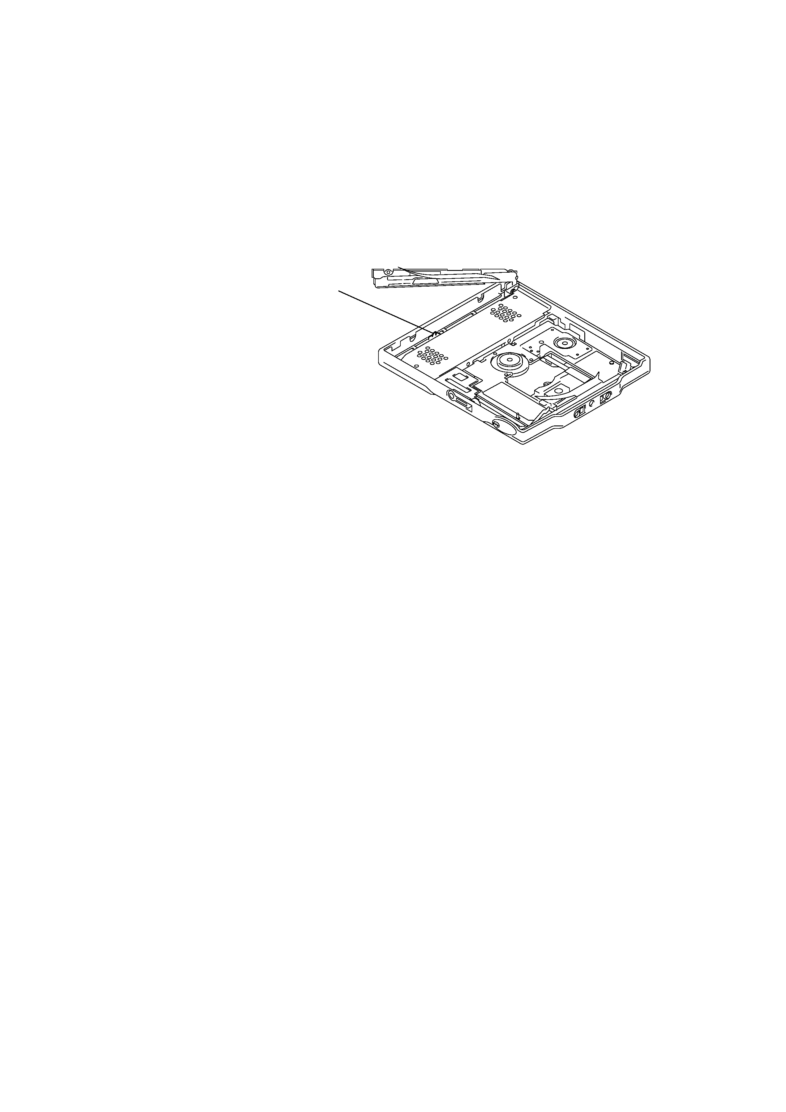
SERVICING NOTE
When repairing this device with the power on, if you remove the main board, this device stops working.
In this case, you work without the device stopping by fastening the hook of the Open/Close detection switch (S809).
Open/Ciose detection switch (S809)
4
MZ-E909
SECTION 2
GENERAL
This section is extracted from
instruction manual.
To
Find the beginning of
the current track or
the previous track3)
Find the beginning
of the next track4)
Go backwards
while playing
Go forward
while playing
Pause
Remove the MD
2) You can turn off the beep sound. For more details, see "Turning off the beep sound."
3) If you turn the control towards . on the remote control (or press . on the player) during the
first track of the disc, the player goes to the beginning of the last track on the disc.
4) If you turn the control towards N> on the remote control (or press > N on the player) during
the last track of the disc, the player goes to the beginning of the first track on the disc.
5) If you open the lid, the playback will begin from the beginning of the first track (except when disc
information is stored to the personal disc memory or when group mode is on).
z
The MZ-E909 supports the newly developed DSP TYPE-R for ATRAC.
It thus allows you to enjoy TYPE-R high-quality sound from MDs recorded in SP stereo on TYPE-R-
equipped MD decks, etc.
Note
When removing the disc, make sure to press x first, and then slide OPEN.
Viewing the display window of the remote control
Track number Track name6) or elapsed time of the track
6) Appears only with MDs that have been electronically labeled.
z
· The player can play the track recorded by 2
× or 4 × long playing mode (LP2 or LP4). Normal stereo
playback, LP2 stereo playback, LP4 stereo playback or monaural playback is automatically selected to
match the audio source.
· The display on the remote control will turn off shortly after you press x.
Do this (Beeps2) in the headphones)
Turn the control towards . on the remote control once
(three short beeps). (Or press . on the player once.)
Turn the control towards . on the remote control repeatedly
(continuous three short beeps). (Or press . on the player
repeatedly.)
Turn the control towards N> on the remote control (two
short beeps).
Press > N on the player once.
Turn and hold the control towards . on the remote control.
Hold down . on the player.
Turn and hold the control towards N> on the remote control.
Hold down > N on the player.
Press X on the remote control (continuous short beeps).
Press X on the remote control again to resume play.
Press x, and then slide OPEN.5)
Playing an MD
Insert an MD.
1
2
3
Play an MD.
2
x
X
1N>
VOL+
VOL
.
> N
.
VOLUME +/
GROUP
x
1
Turn the control towards N> on the remote control (or press > N
on the player) to play the disc.
A short beep sounds in the headphones/earphones when using the remote control.
The LED flashes and then lights up.
2
Pull and turn VOL +/ on the remote control (or press VOLUME +/ on the
player) to adjust the volume.
The volume indicator appears in the display, allowing you to check the
volume level. After you adjust the volume, push back the control.
To stop play, press x.
Playback starts from the point you last stopped playing. To start playback from the
beginning of the disc, turn and hold the control towards N> on the remote control
(or hold down > N on the player) for 2 seconds or more.
1) The LED indicates the current operating status by the lighting up in the following colors.
When the battery power is exhausted, the LED starts flashing. For more details, see
"When to replace or recharge the battery."
LED color
Operating status
Red
Normal play (The LED lights up continuously)
Green
Group mode* (The LED lights up continuously)
Orange
Group skip mode* (The LED lights for about 5 seconds)
*For more details, see "Using the group function."
1
2
Insert an MD with the label side facing up, pushing the
MD to the direction of the arrow in the illustration.
1
Slide OPEN to open the lid.
2
Insert an MD.
3
Close the lid.
3 Color Info-LED1)
The Player
1
9
7
F
E
C
D
2
8
1 ./x/N> button
2 3 Color Info-LED
3 GROUP button
4 HOLD (Locking the control) switch
5 i (earphones) jack
6 OPEN switch
7 Terminals for charging stand/
dry battery case (at the bottom)
8 VOL +/ button
9 Battery compartment
The earphones with a remote
control
J
+
H
I
K
D
A
L
F
B
E
G
C
1 Headphones/earphones
2 Stereo mini plug
3 X (pause) button
4 SOUND button
5 RPT/ENT (Repeat/Enter) button
6 PLAYMODE button
7 DISPLAY button
8 x (stop) button*
9 Control (./N>)
q; Control VOL +/
Pull and turn to adjust the volume.
qa HOLD (Locking the control) switch
qs Display window
* The stop button also operates as the enter
button, depending on the function.
The display window of the remote
control
F
G
AB
C D E
1 Track number display
2 Charactor information display
3 Disc indication
4 Alarm indication
5 Play mode indication
6 Battery level indication
7 SOUND indication
The battery charging stand
B
A
C
1 Terminals for charging
2 CHARGE lamp
3 DC IN (3V jack) (at the rear)
5
MZ-E909
SECTION 3
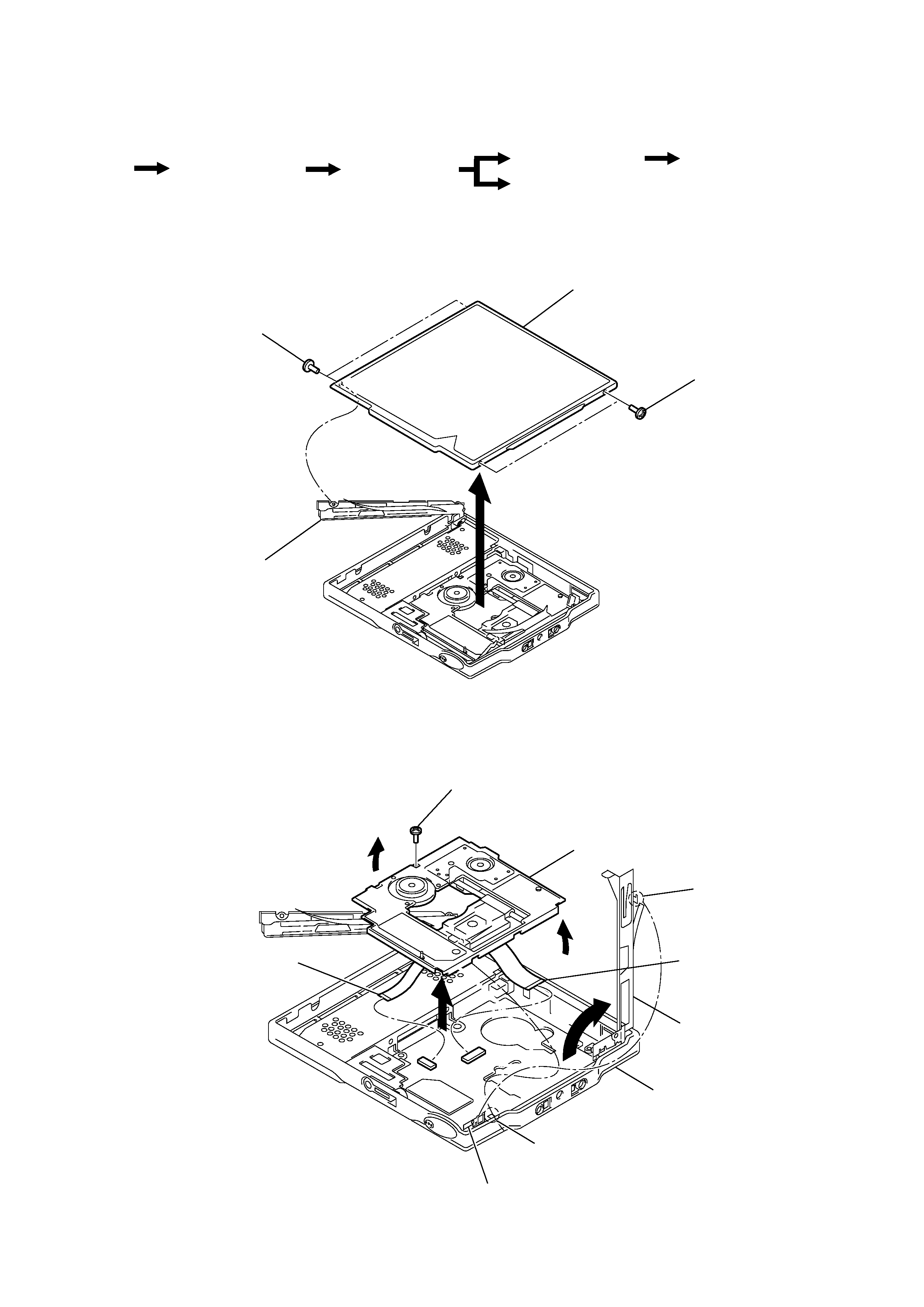
DISASSEMBLY
Note : Follow the disassembly procedure in the numerical order given.
3-1. "LID ASSY, UPPER"
3-2. MECHANISM DECK
r
The equipment can be removed using the following procedure.
2
1
Screws , ES Lock
1
Screws , ES lock
Bracket (L) ASSY
Lid ASSY, upper
4
7
5
2
9
Motor flexible board
(CN551)
6
Claw
8
OP flexible board
(CN501)
1
Move claw away from
bracket (stop) ASSY
3
Screw (LL), step
Bracket (stop) ASSY
Panel, bottom
Bracket (R) ASSY
Mechanism deck
"Lid ASSY Upper"
Set
Optical pick-up ASSY
Mechsnism deck
Bracket (R) ASSY
Main board sub ASSY
Bracket (L) ASSY,
SW board
Ver 1.1 2001.11