SERVICE MANUAL
PORTABLE MINIDISC PLAYER
E Model
Tourist Model
SPECIFICATIONS
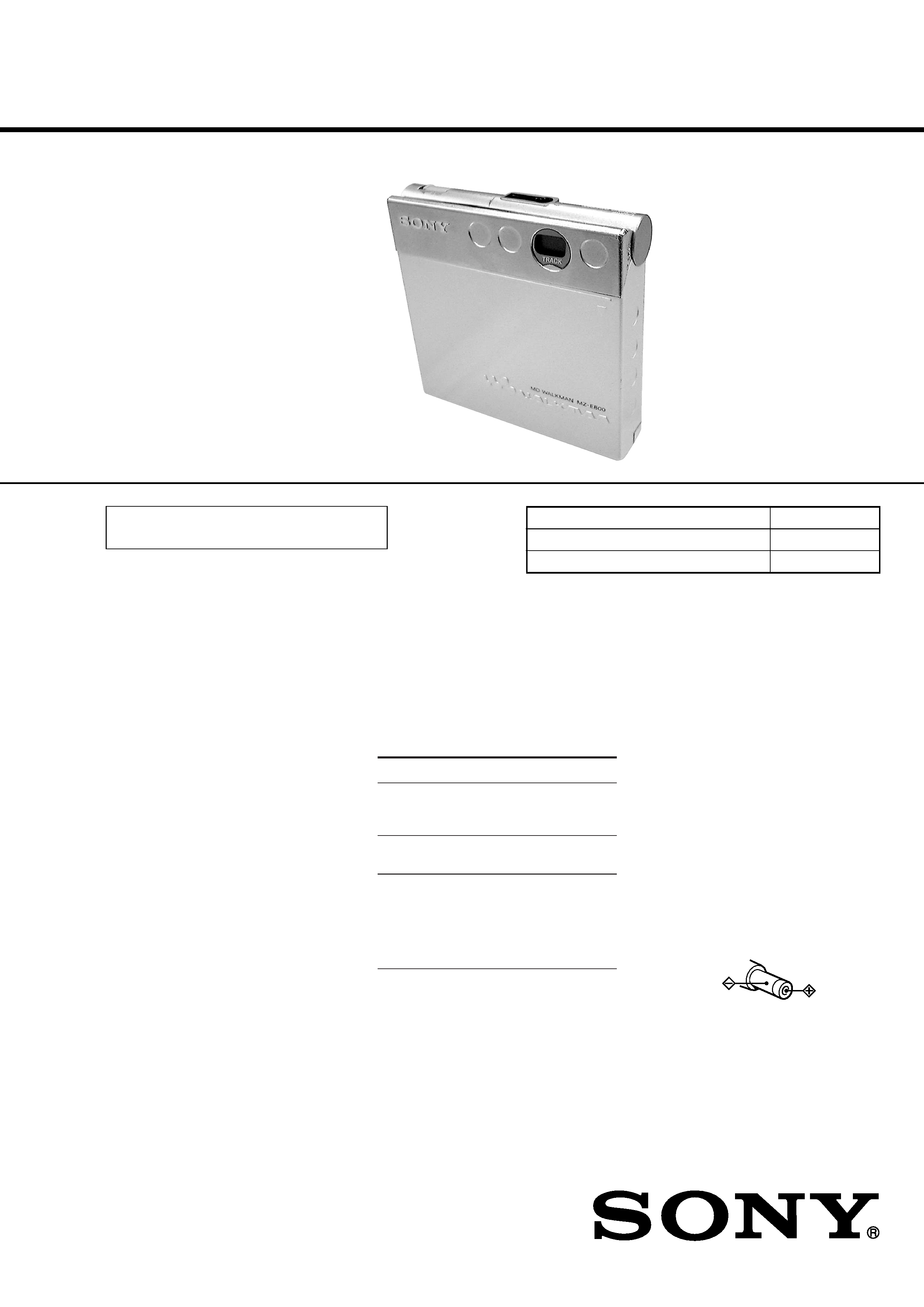
MZ-E800
US and foreign patents licensed from Dolby
Laboratories Licensing Corporation.
Photo: Silver type
Model Name Using Similar Mechanism
NEW
MD Mechanism Type
MT-MZE800-170
Optical Pick-up Mechanism Type
LCX-2E
System
Audio playing system
MiniDisc digital audio system
Laser diode properties
Material: GaAlAs
Wavelength:
= 790 nm
Emission duration: continuous
Laser output: less than 44.6
µW*
* This output is the value measured at a distance
of 200 mm from the objective lens surface on
the optical pick-up block with 7 mm aperture.
Revolutions
600 rpm to 2250 rpm
Error correction
Advanced Cross Interleave Reed Solomon Code
(ACIRC)
Sampling frequency
44.1 kHz
Coding
Adaptive TRansform Acoustic Coding (ATRAC)
Modulation system
EFM (Eight to Fourteen Modulation)
Number of channels
2 stereo channels
1 monaural channel
Frequency response
20 to 20,000 Hz
± 3 dB
Wow and Flutter
Below measurable limit
Outputs
Earphones: stereo mini-jack, maximum output
level 5 mW + 5 mW, load impedance 16 ohms
General
Power requirements
Nickel metal hydride rechargeable battery
One NH-14WM (supplied): 1.2V, 1,400 mAh
One LR6 (size AA) battery (not supplied)
Sony AC Power Adaptor* (supplied) connected
to the DC IN 3V jack
Battery operation time
Dimensions
Approx. 79.5
× 76.7 × 17.0 mm (w/h/d) (not
including projecting parts and controls)
Mass
Approx. 110g (the player only)
Supplied accessories
Earphones with a remote control (1)
Charging stand (1)
Nickel metal hydride rechargeable battery (1)
AC power adaptor (1)
Dry battery case (1)
Rechargeable battery carrying case (1)
Carrying pouch (1)
Design and specifications are subject to change
without notice.
Playback
Approx. 24 hours*
Approx. 37 hours
Approx. 64 hours
Battery life*
Batteries
Ni-MH
rechargeable battery
(NH-14WM)
One (size AA)
alkaline battery**
One (size AA)
alkaline battery**
and a Ni-MH
rechargeable
battery
(NH-14WM)
* With a fully charged battery
** When using a LR6 (SG) Sony "STAMINA"
alkaline dry battery (produced in Japan).
Note
The battery life may be shorter depending on
operating conditions, the surrounding
temperature, and the battery type.
About power sources
· For use in your house or car: Use the
supplied AC power adaptor or the
DCC-E230 car battery cord (not supplied)
to supply power to the player. Do not use
any other power supply.
Polarity of the plug
Ver 1.1 2001.02
9-927-939-12
Sony Corporation
2001B0500-1
Audio Entertainment Group
C
2001.2
General Engineering Dept.

2
TABLE OF CONTENTS
1.
SERVICING NOTES ............................................... 3
2.
GENERAL ................................................................... 6
3.
DISASSEMBLY ......................................................... 7
4.
TEST MODE .............................................................. 12
5.
ELECTRICAL ADJUSTMENTS ......................... 17
6.
DIAGRAMS
6-1. Block Diagram MAIN Section (1/2) ......................... 21
6-2. Block Diagram MAIN Section (2/2) ......................... 23
6-3. Block Diagram DISPLAY/KEY CONTROL/
POWER SUPPLY Section ........................................... 25
6-4. Printed Wiring Board ...................................................... 27
6-5. Schematic Diagram MAIN Board (1/4) .................... 29
6-6. Schematic Diagram MAIN Board (2/4) .................... 31
6-7. Schematic Diagram MAIN Board (3/4) .................... 33
6-8. Schematic Diagram MAIN Board (4/4) .................... 35
6-9. IC Pin Function Description ........................................... 40
7.
EXPLODED VIEWS ................................................ 47
8.
ELECTRICAL PARTS LIST ............................... 50
SAFETY-RELATED COMPONENT WARNING!!
COMPONENTS IDENTIFIED BY MARK 0 OR DOTTED
LINE WITH MARK 0 ON THE SCHEMATIC DIAGRAMS
AND IN THE PARTS LIST ARE CRITICAL TO SAFE
OPERATION. REPLACE THESE COMPONENTS WITH
SONY PARTS WHOSE PART NUMBERS APPEAR AS
SHOWN IN THIS MANUAL OR IN SUPPLEMENTS PUB-
LISHED BY SONY.
Features
· Compact body with newly developed
head-loading system.
Insert or eject an MD with the slightest
touch of a finger.
· Simple-to-charge folding standup
battery charger
Insert the MD player into the folding
standup battery charger for simple, one-
step charging. By connecting an optional
car battery cord to the battery charger, you
can listen to the player in the car without
worrying about battery rundown.
· LCD display built into player for easy
viewing in the car
An easy-to-see LCD display built into the
player allows you to monitor track
numbers when the remote control display
is out of view.
· Personalized sound through Digital
Sound Preset functions
You can store two sets of sound quality
adjustments (made during playback) to
two switches.
· Small body almost the size of a MiniDisc
jacket
· Low power-consumption design for
extended battery life.
· Easy-to-operate earphones remote
control with backlit LCD
· Shock-resistant memory offsets up to 40
seconds of optical read errors.
Notes on chip component replacement
· Never reuse a disconnected chip component.
· Notice that the minus side of a tantalum capacitor may be dam-
aged by heat.
Flexible Circuit Board Repairing
· Keep the temperature of the soldering iron around 270 °C dur-
ing repairing.
· Do not touch the soldering iron on the same conductor of the
circuit board (within 3 times).
· Be careful not to apply force on the conductor when soldering
or unsoldering.
CAUTION
Use of controls or adjustments or performance of procedures
other than those specified herein may result in hazardous ra-
diation exposure.
3
NOTES ON HANDLING THE OPTICAL PICK-UP
BLOCK OR BASE UNIT
The laser diode in the optical pick-up block may suffer electro-
static break-down because of the potential difference generated
by the charged electrostatic load, etc. on clothing and the human
body.
During repair, pay attention to electrostatic break-down and also
use the procedure in the printed matter which is included in the
repair parts.
The flexible board is easily damaged and should be handled with
care.
NOTES ON LASER DIODE EMISSION CHECK
Never look into the laser diode emission from right above when
checking it for adjustment. It is feared that you will lose your sight.
NOTES ON HANDLING THE OPTICAL PICK-UP BLOCK
(LCX-2E)
The laser diode in the optical pick-up block may suffer electro-
static break-down easily. When handling it, perform soldering
bridge to the laser-tap on the flexible board. Also perform mea-
sures against electrostatic break-down sufficiently before the op-
eration. The flexible board is easily damaged and should be handled
with care.
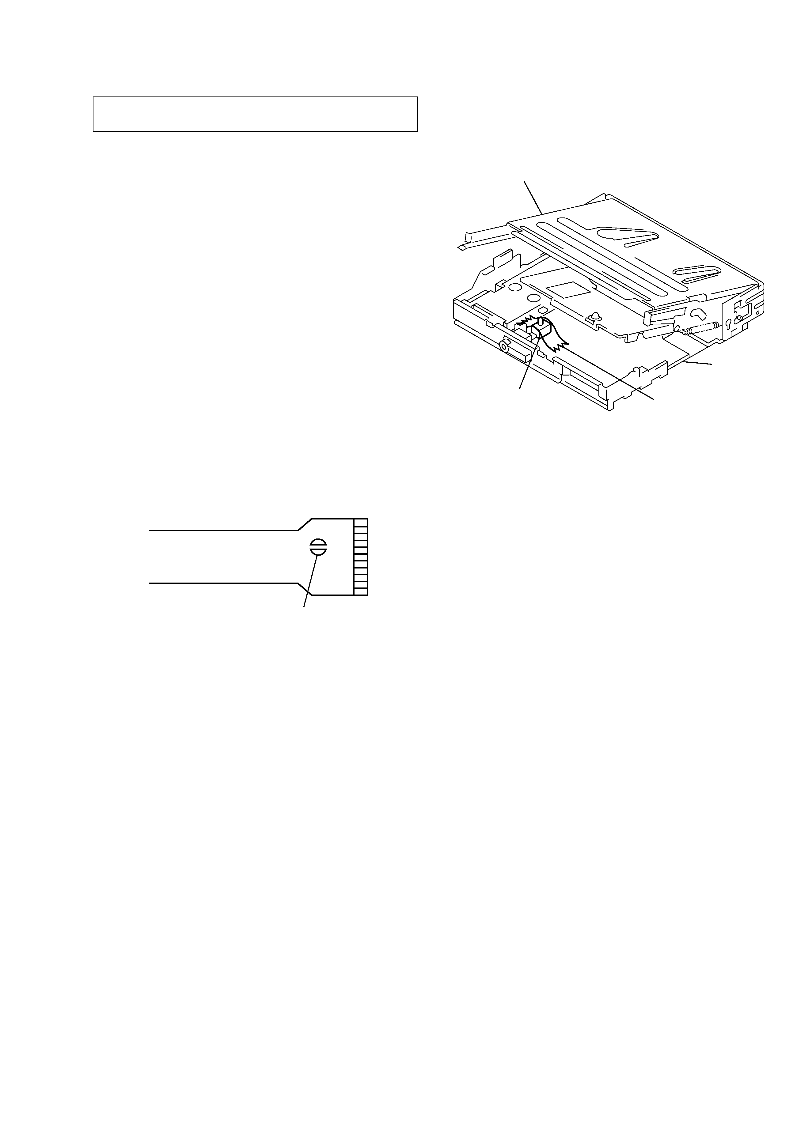
OPTICAL PICK-UP FLEXIBLE BOARD
SECTION 1
SERVICING NOTES
· In performing the repair with the power supplied to the set,
removing the MAIN board causes the set to be disabled.
In such a case, fix a convex part of the open/close detect switch
(S809 on MAIN board) with a tape in advance.
· Replacement of CXD2661GA-2 (IC601) and CXR701080-
016GA (IC801) used in this set requires a special tool. There-
fore, they cannot be replaced.
· On the set having the microcomputer version 1.000, the NV reset
failure will occur.
Therefore, in executing the NV reset during electrical adjustment,
follow the troubleshooting method of NV reset to perform the
NV reset (see page 17).
laser-tap
mechanism deck section
MAIN board
tape
open/close detect switch
(S809)
4
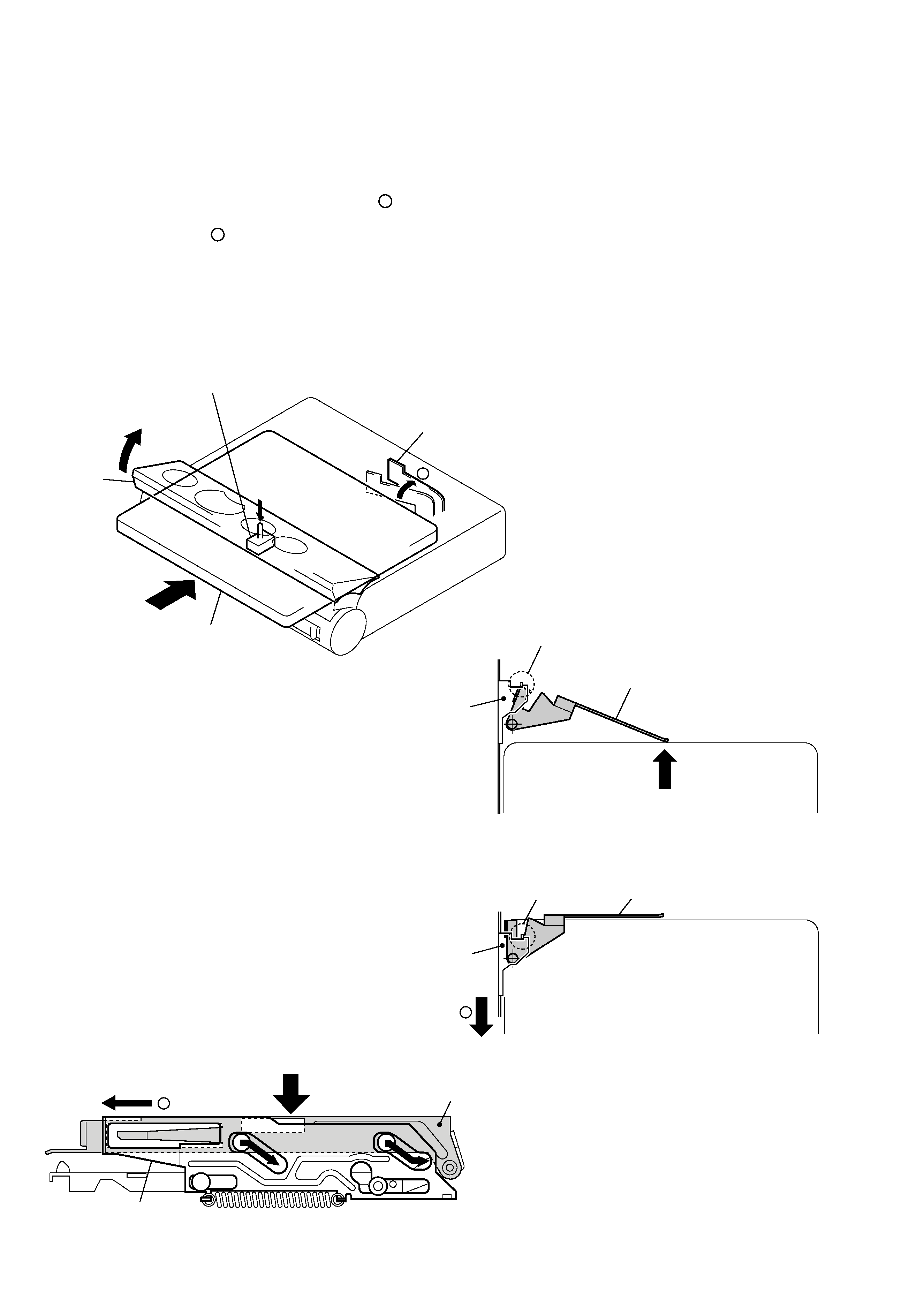
open/close detect switch (S809)
eject lever 2
shutter 1
Disc insertion.
ON
(Fig. 1)
a
eject lever 2
Lock
slider 4
Disc insertion.
(Fig. 2)
eject lever 2
Unlock
slider 4
(Fig. 3)
b
slider 4
(Fig. 4)
b
holder assy 3
Moving down to MAIN board side (downward).
OPERATION OF MECHANISM
· When a disc is loaded.
Open the shutter 1. (Fig. 1)
j
When a disc is inserted, the Eject lever 2 moves in arrow
direction and the holder Assy 3 is unlocked. (Fig. 1 - Fig. 4)
j
The slider 4 slides in arrow
direction, and the holder Assy 3 moves down to the MAIN board side (downward). (Fig. 4)
j
When a disc lowers, the open/close detect switch (S809) turns on. (Fig. 1)
j
The Wake-up mode becomes active and the power circuit starts to operate.
a
b
5
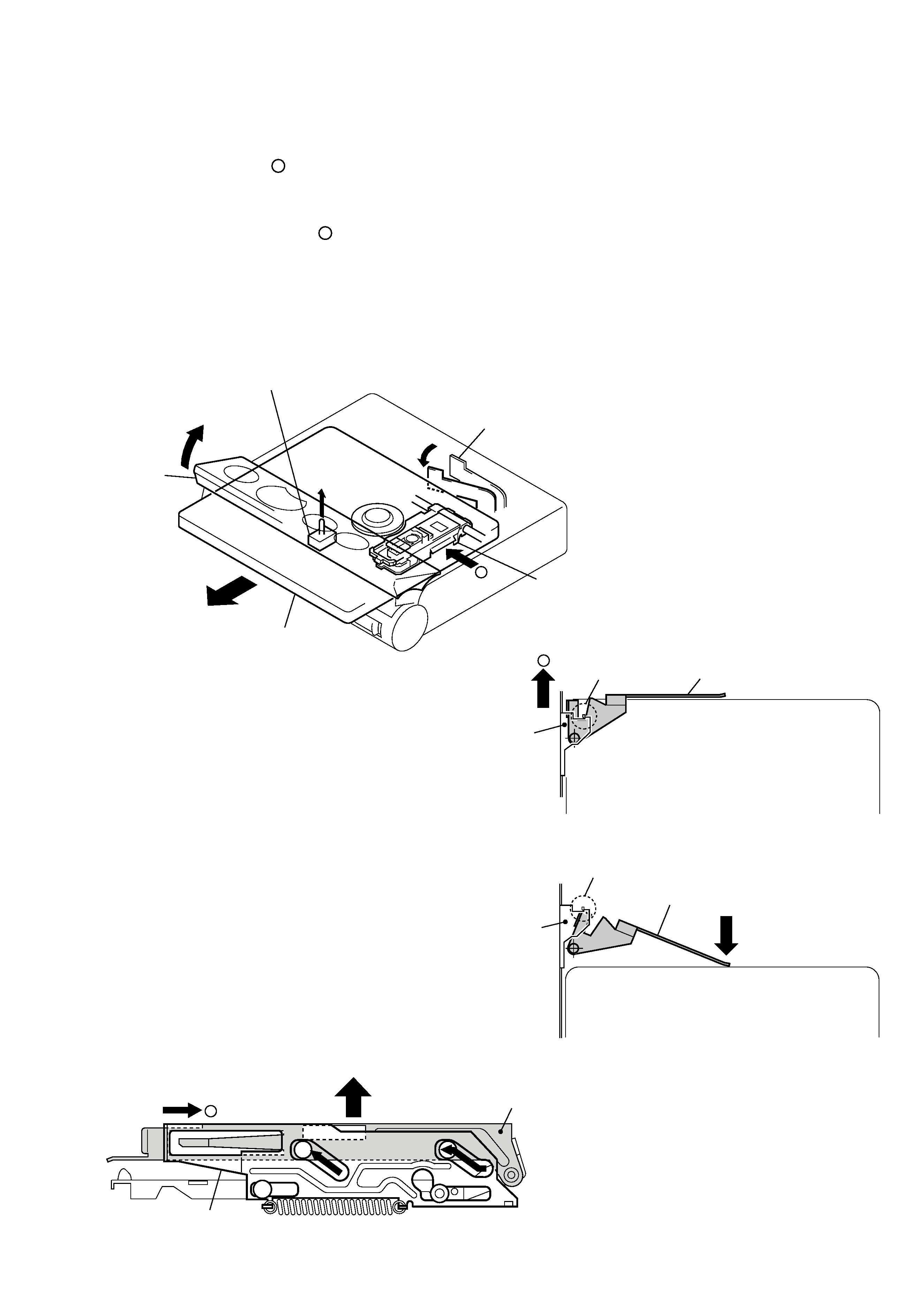
· When a disc is unloaded.
Open the shutter 1. (Fig. 5)
j
The slider 2 slides in arrow
direction, and the holder Assy 3 moves up. (Fig. 6, Fig. 8)
j
When a disc rises, the open/close detect switch (S809) turns off. (Fig. 5)
j
The optical block 4 moves in arrow
direction (inward). (Fig. 5)
j
The disc 6 is pushed out by the Eject lever 5 and ejected from the holder Assy 3. (Fig. 7)
j
The Sleep mode becomes active and the power supply stops.
a
b
b
open/close detect switch (S809)
eject lever 5
shutter 1
Disc ejection. 6
OFF
(Fig. 5)
optical block 4
a
eject lever 5
Unlock
slider 2
(Fig. 6)
eject lever 5
Lock
slider 2
Disc ejection. 6
(Fig. 7)
a
slider 2
(Fig. 8)
holder assy 3
UP