MICROFILM
SERVICE MANUAL
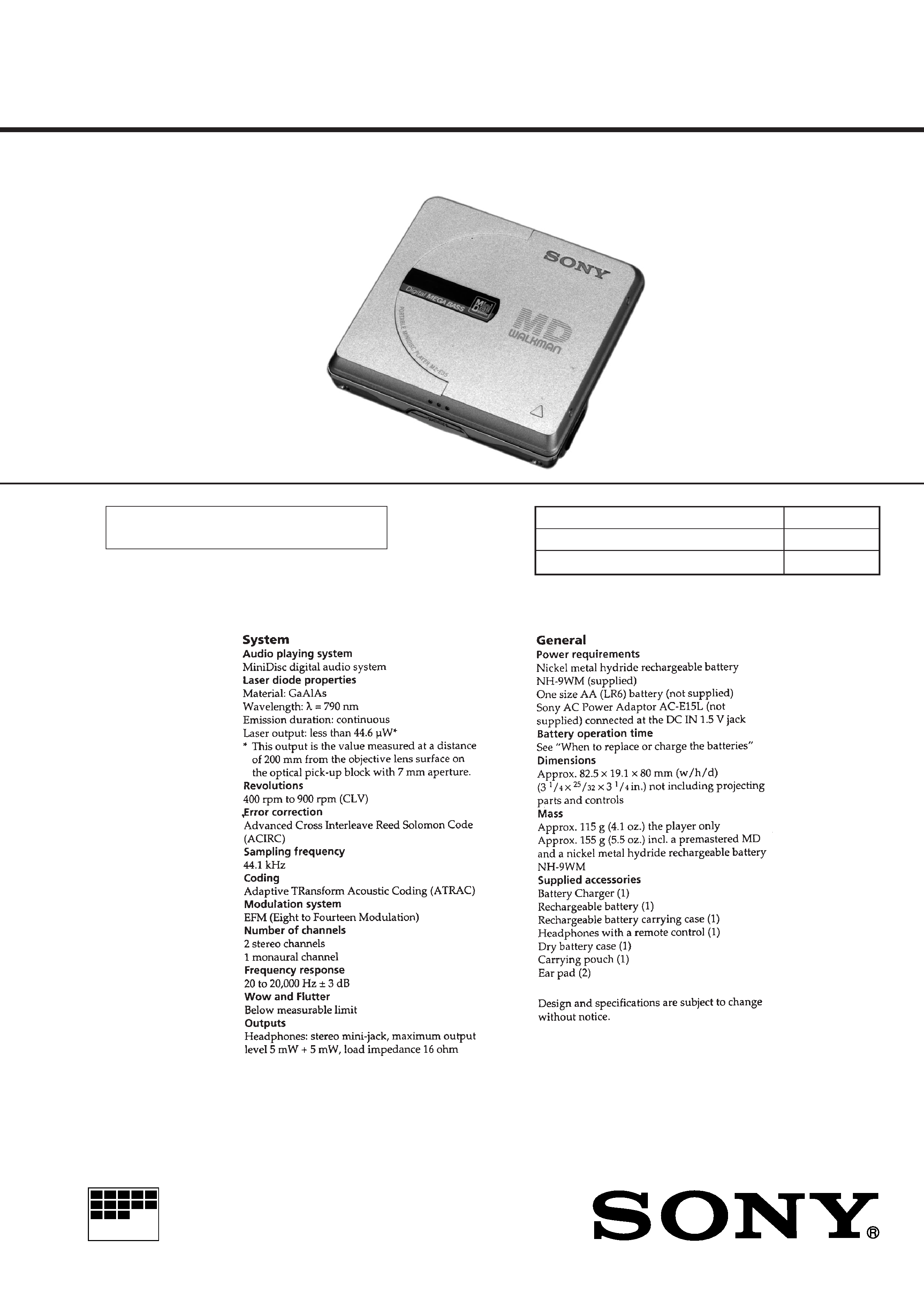
PORTABLE MINIDISC PLAYER
US Model
AEP Model
UK Model
E Model
Model Name Using Similar Mechanism
NEW
MD Mechanism Type
MT-MZE35-140
Optical Pick-up Type
ODX-1B
SPECIFICATIONS
MZ-E35
US and foreign patents licensed from Dolby
Laboratories Licensing Corporation.
2
TABLE OF CONTENTS
1.
GENERAL ................................................................... 3
2.
DISASSEMBLY ......................................................... 5
3.
TEST MODE .............................................................. 8
4.
ELECTRICAL ADJUSTMENTS ......................... 11
5.
DIAGRAMS
5-1. Block Diagram ................................................................ 13
5-2. Printed Wiring Board
(US, Hong Kong Model) ................................................. 15
5-3. Printed Wiring Board
(AEP, UK, E, French Model) .......................................... 19
5-4. Schematic Diagram ......................................................... 21
5-5. IC Pin Function Description ........................................... 30
6.
EXPLODED VIEWS ................................................ 33
7.
ELECTRICAL PARTS LIST ............................... 35
SERVICING NOTES
Flexible Circuit Board Repairing
· Keep the temperature of the soldering iron around 270 °C dur-
ing repairing.
· Do not touch the soldering iron on the same conductor of the
circuit board (within 3 times).
· Be careful not to apply force on the conductor when soldering
or unsoldering.
Notes on chip component replacement
· Never reuse a disconnected chip component.
· Notice that the minus side of a tantalum capacitor may be dam-
aged by heat.
SAFETY-RELATED COMPONENT WARNING!!
COMPONENTS IDENTIFIED BY MARK
! OR DOTTED
LINE WITH MARK
! ON THE SCHEMATIC DIAGRAMS
AND IN THE PARTS LIST ARE CRITICAL TO SAFE
OPERATION. REPLACE THESE COMPONENTS WITH
SONY PARTS WHOSE PART NUMBERS APPEAR AS
SHOWN IN THIS MANUAL OR IN SUPPLEMENTS PUB-
LISHED BY SONY.
CAUTION
Use of controls or adjustments or performance of procedures
other than those specified herein may result in hazardous ra-
diation exposure.
This MiniDisc player is classified as a CLASS 1
LASER product.
The CLASS 1 LASER PRODUCT label is located
on the bottom exterior.
3
SECTION 1
GENERAL
This section is extracted from
instruction manual.
4
8
SECTION 3
TEST MODE
300
V3.000
300
Remote controller LCD
Main unit LCD
ROM version
display (Ver3.00
or Ver3.20)
General
· In the TEST mode, this set provides the Auto mode in which
both CD and MO are adjusted automatically. In the Auto mode,
whether a disc is CD or MO is discriminated, then each
adjsutment is automatically executed sequentially. If a fault is
found, it is displayed. Also, in the Servo mode, each item can be
adjusted automatically.
Entering TEST Mode
Bridge the TAP801 (TEST) on MAIN board (connect IC801 #TM to
GND), and turn the power on.
Then, press
( key and the TEST mode is activated.
Releasing TEST Mode
Turn the power off, and remove the bridge from TAP801 (TEST)
on MAIN board.
Operation in TEST Mode
In the TEST mode, the LCD display is as shown below:
· ROM version display
All ON All OFF are repeated.
· To hold the display for confirmation, press the PLAY MODE
key.
Display
in
TEST
Mode
+key
key
+,key
+,key
+,
key
pkey
pkey
pkey
(key
(key
pkey
AUTO Mode
(Auto?)
SERVO Mode
0 0 0
AUDIO Mode
1 0 0
POWER Mode
3 0 0
MANUAL
Mode
(Manu?)
(
) for Remote controller LCD display
(Start?)
+,key
+,key
pkey
pkey
pkey
pkey
pkey
pkey
12
3
(To page 9 )
SERVO Mode
0 0 0
OFFSET Adj.
0 1 0
Each time (key is press-
ed,
011-013 modes
are switched. (For each
mode, see relevant table)
Each time (key is press-
ed,
021-024 modes
are switched. (For each
mode, see relevant table)
Each time (key is press-
ed,
031-039 modes
are switched. (For each
mode, see relevant table)
LASER
POWER Adj.
0 2 0
MO Adj.
0 3 0
(key
(key
(key
(key
(key
(key
(key
Configuration of TEST Mode
The TEST mode configuration of this set is as follows:
SERVO Mode
· Enter the TEST mode, press VOL
- key and ( key to select
the SERVO mode.
· When the second digit of mode number is not 0 and the first
digit is 0 (010, 020, 030, etc.), the optical pickup moves to out-
side track or inside track with
+ key or = key respec-
tively.
· To select other modes, refer to the TEST mode configuration.
1. Configuration of SERVO Mode