MICROFILM
SERVICE MANUAL
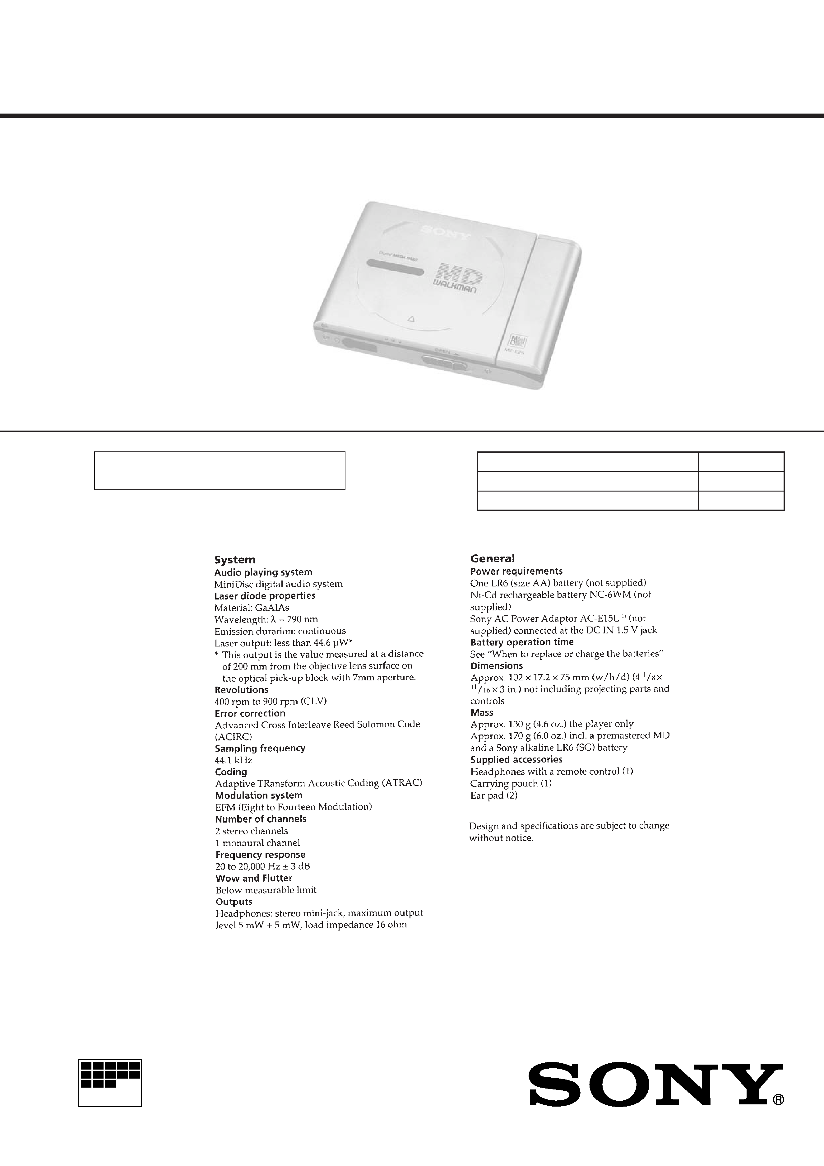
PORTABLE MINIDISC PLAYER
US Model
Canadian Model
AEP Model
UK Model
E Model
Australian Model
Model Name Using Similar Mechanism
NEW
Mechanism Type
MT-MZE35-140
Optical Pick-up Name
ODX-1B
SPECIFICATIONS
MZ-E25
US and foreign patents licensed from Dolby
Laboratories Licensing Corporation.
2
TABLE OF CONTENTS
1.
GENERAL ................................................................... 3
2.
DISASSEMBLY ......................................................... 5
3.
TEST MODE .............................................................. 9
4.
ELECTRICAL ADJUSTMENTS ......................... 12
5.
DIAGRAMS
5-1. Block Diagram ................................................................ 14
5-2. Printed Wiring Board ...................................................... 16
5-3. Schematic Diagram ......................................................... 19
5-4. IC Pin Function Description ........................................... 28
6.
EXPLODED VIEWS ................................................ 31
7.
ELECTRICAL PARTS LIST ............................... 33
Flexible Circuit Board Repairing
· Keep the temperature of the soldering iron around 270 °C dur-
ing repairing.
· Do not touch the soldering iron on the same conductor of the
circuit board (within 3 times).
· Be careful not to apply force on the conductor when soldering
or unsoldering.
Notes on chip component replacement
· Never reuse a disconnected chip component.
· Notice that the minus side of a tantalum capacitor may be dam-
aged by heat.
ATTENTION AU COMPOSANT AYANT RAPPORT
À LA SÉCURITÉ!
LES COMPOSANTS IDENTIFIÉS PAR UNE MARQUE
!
SUR LES DIAGRAMMES SCHÉMATIQUES ET LA LISTE
DES PIÈCES SONT CRITIQUES POUR LA SÉCURITÉ
DE FONCTIONNEMENT. NE REMPLACER CES COM-
POSANTS QUE PAR DES PIÈCES SONY DONT LES
NUMÉROS SONT DONNÉS DANS CE MANUEL OU
DANS LES SUPPLÉMENTS PUBLIÉS PAR SONY.
SAFETY-RELATED COMPONENT WARNING!!
COMPONENTS IDENTIFIED BY MARK
! OR DOTTED
LINE WITH MARK
! ON THE SCHEMATIC DIAGRAMS
AND IN THE PARTS LIST ARE CRITICAL TO SAFE
OPERATION. REPLACE THESE COMPONENTS WITH
SONY PARTS WHOSE PART NUMBERS APPEAR AS
SHOWN IN THIS MANUAL OR IN SUPPLEMENTS PUB-
LISHED BY SONY.
CAUTION
Use of controls or adjustments or performance of procedures
other than those specified herein may result in hazardous ra-
diation exposure.
This MiniDisc player is classified as a CLASS 1
LASER product.
The CLASS 1 LASER PRODUCT lavel is located
on the rear exterior.
3
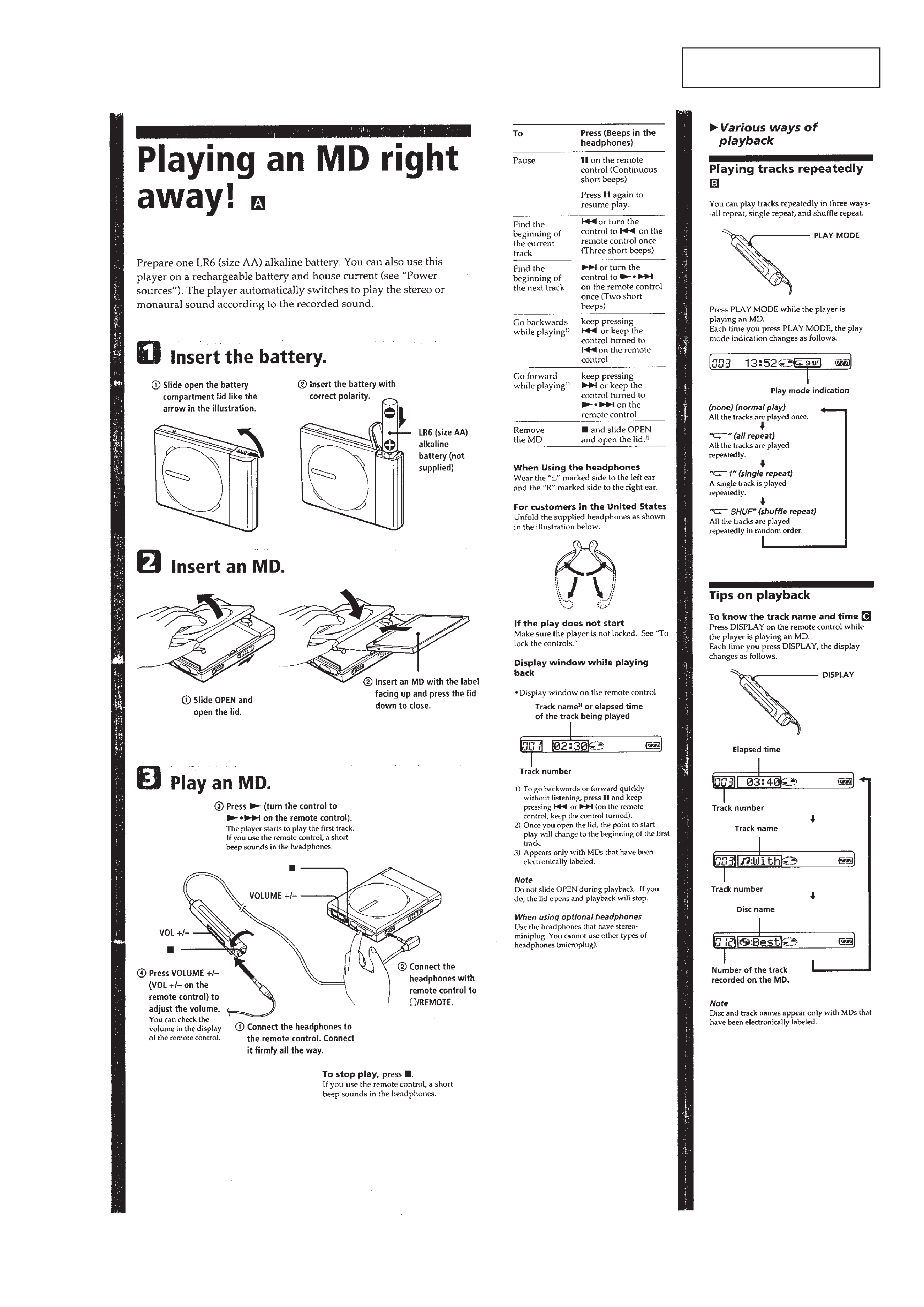
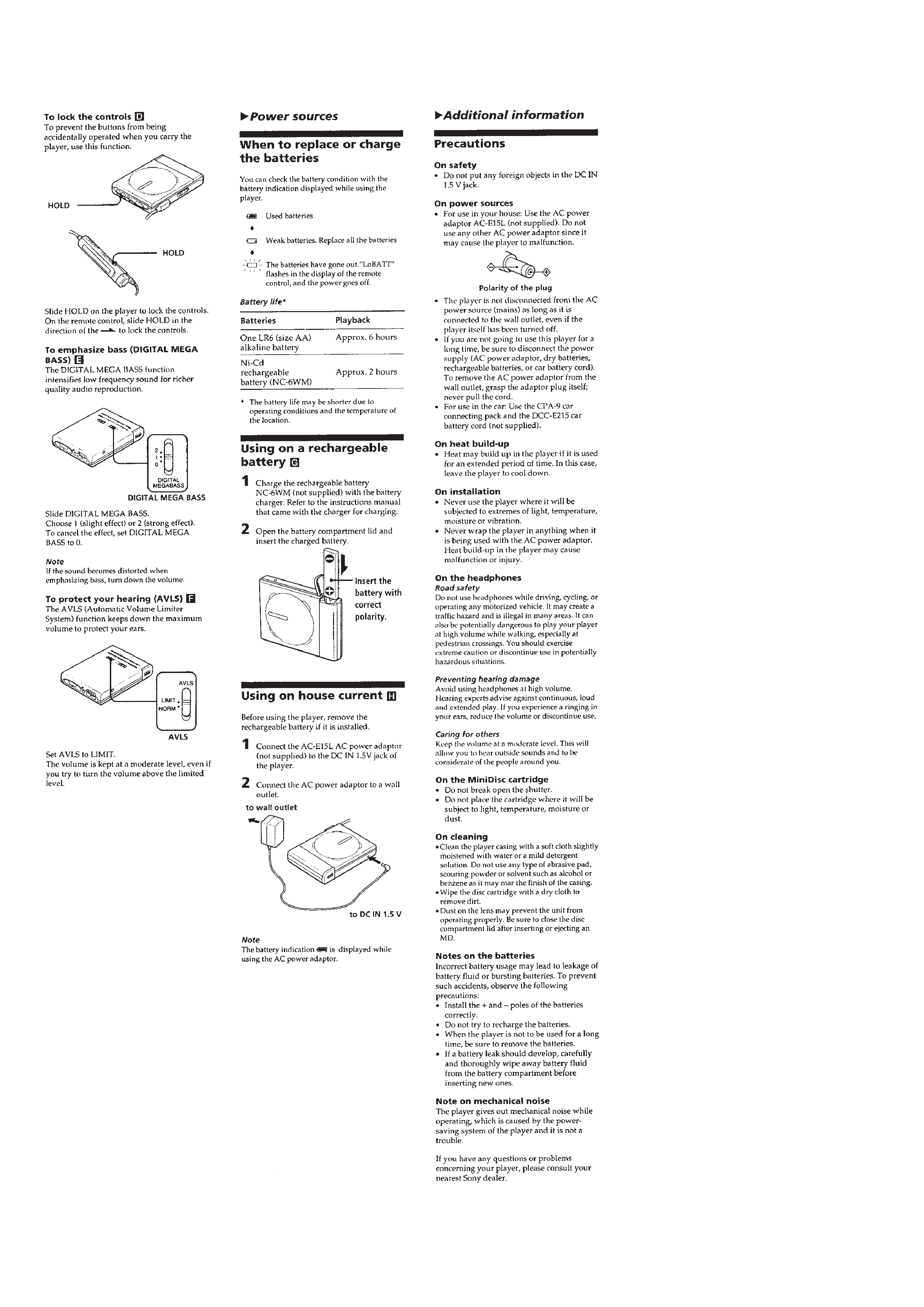
SECTION 1
GENERAL
This section is extracted from
instruction manual.
4
5
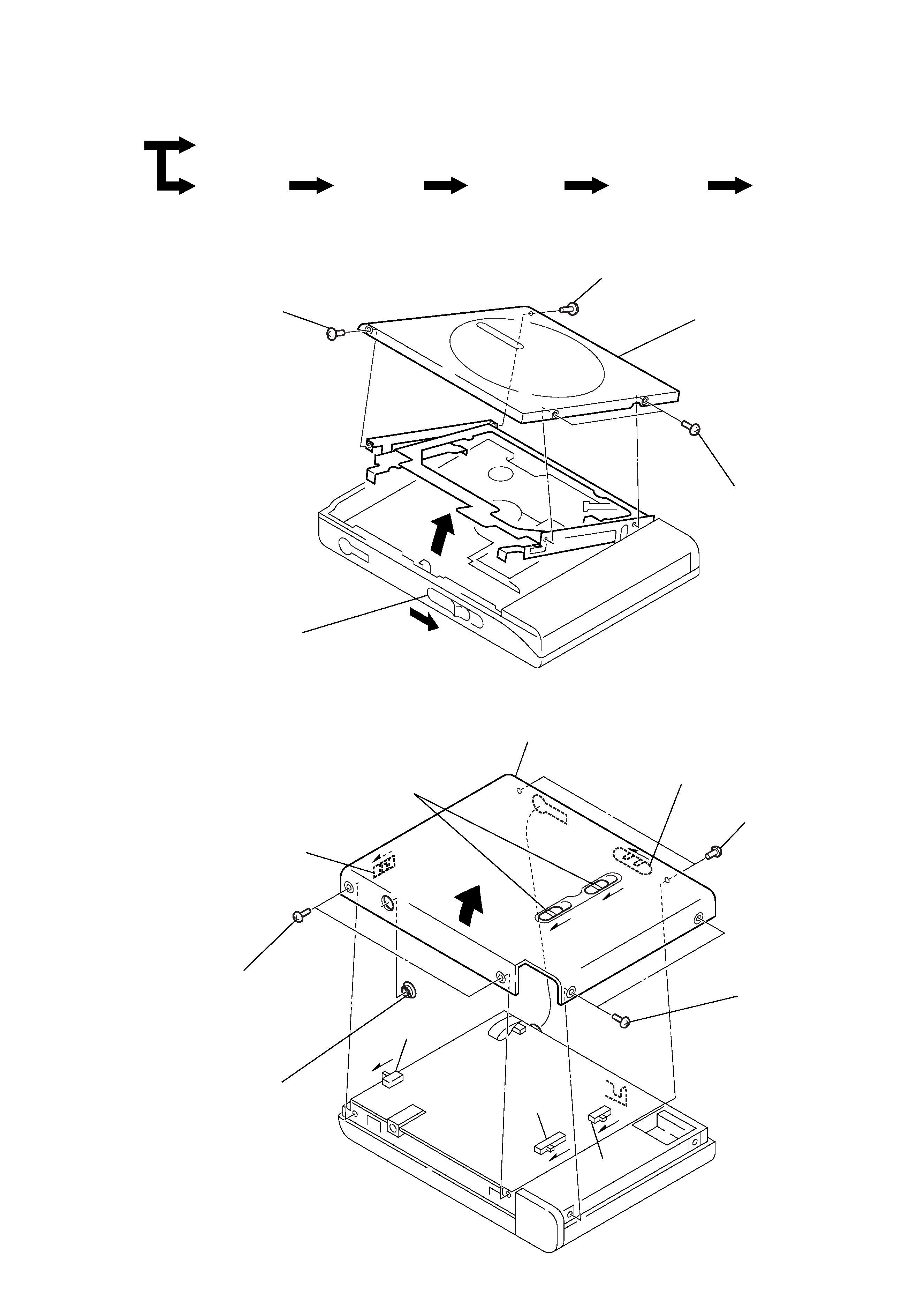
UPPER LID ASS'Y
BOTTOM PANEL ASS'Y
Note on installation:
When mounting, shift S301, S802, and S805 in
the arrow direction, then shift the knobs (HOLD),
(DOLBY), and (OPEN) in the arrow direction so
as to adjust each knob and switch position.
Note: Follow the disassembly procedure in the numerical order given.
SECTION 2
DISASSEMBLY
· This set can be disassembled in the order shown below.
SET
UPPER LID ASS'Y
BOTTOM
PANEL ASS'Y
MAIN BOARD
ORNAMENTAL
BELT ASS'Y
MECHANISM
DECK SECTION
(MT-MZE35-140)
OPTICAL PICK-UP
(ODX-1B)
SECTION ASS'Y
2 precision screw
(M1.4)
1 Moving the knob (OPEN) in the direction A,
open the upper LID ass'y.
2 precision screw
(M1.4)
2 two precision screws
(M1.4)
3 upper LID ass'y
A
2 bottom panel ass'y
1 two precision screws
(M1.4)
knob (OPEN)
knob (DOLBY)
knob (HOLD)
S802
1 two precision screws
(M1.4)
1 two precision screws
(M1.4)
3 collar (DC IN)
S301
S805