SERVICE MANUAL
PORTABLE MD PLAYER
MZ-DH10P
Ver. 1.2 2005.05
SPECIFICATIONS
9-879-552-03
2005E05-1
© 2005.05
Sony Corporation
Personal Communications Business Division
Published by Sony Engineering Corporation
US and foreign patents licensed from Dolby Laboratories.
Model Name Using Similar Mechanism
NEW
MD Mechanism Type
MT-MZDH10P-181
Optical Pick-up Name
ABX-UJ
US Model
AEP Model
UK Model
Chinese Model
Tourist Model
· SonicStage is trademark or registered trademark of Sony Corporation.
·MD Simple Burner, OpenMG, "MagicGate", "MagicGate Memory Stick", "Memory Stick", Hi-MD, Net
MD, ATRAC, ATRAC3, ATRAC3plus and their logos are trademarks of Sony Corporation.
· Microsoft, Windows, Windows NT and Windows Media are trademarks or registered trademarks of Microsoft
Corporation in the United States and /or other countries.
· IBM and PC/AT are registered trademarks of International Business Machines Corporation.
·Macintosh is a trademark of Apple Computer, Inc. in the United States and/ or other countries.
·Pentium is a trademark or registered trademark of Intel Corporation.
· All other trademarks and registered trademarks are trademarks or registered trademarks of their respective
holders.
·TM and ® marks are omitted in this manual.
· CD and music-related data from Gracenote, Inc., copyright © 2000-2004 Gracenote. Gracenote CDDB®
Client Software, copyright 2000-2004 Gracenote. This product and service may practice one or more of the
following U.S. Patents: #5,987,525; #6,061,680; #6,154,773, #6,161,132, #6,230,192, #6,230,207, #6,240,459,
#6,330,593, and other patents issued or pending. Services supplied and/or device manufactured under license
for following Open Globe, Inc. United States Patent 6,304,523.
Gracenote is a registered trademarks of Gracenote. The Gracenote logo and logotype, and the "Powered by
Gracenote" logo are trademarks of Gracenote.
Program © 2001, 2002, 2003, 2004, 2005 Sony Corporation Documentation © 2005 Sony Corporation
*
*

MZ-DH10P
2
Supplied Accessories
AC power adaptor
Remote control 1)
USB cradle
Earphones
Dedicated USB cable2)
LIP-4WM Lithium-ion rechargeable battery
Rechargeable battery case
Carrying pouch
Ferrite core (for the remote cord, AEP and UK models only)
CD-ROM3) (SonicStage/MD Simple Burner)
Operating Instructions
1) For US model, remote control with a ferrite core is supplied.
2) For Chinese and Tourist models, the ferrite core is not attached to the dedicated USB cable.
3) Do not play a CD-ROM on an audio CD player.
Ver. 1.2
120V AC, 60Hz (US model)
220V AC, 50Hz (Chinese model)
MZ-DH10P
3
TABLE OF CONTENTS
1.
SERVICING NOTES ............................................... 4
2.
GENERAL ................................................................... 5
3.
DISASSEMBLY
3-1.
Disassembly Flow ...........................................................
6
3-2.
Panel (Bottom) Block ......................................................
7
3-3.
Camera Module ...............................................................
7
3-4.
MAIN Board ....................................................................
8
3-5.
Panel (Upper) Block ........................................................
8
3-6.
Ornamental Belt ..............................................................
9
3-7.
Mechanism Deck (MT-MZDH10P-181),
Battery Case ....................................................................
9
3-8.
Gear (SA), Gear (SB) ...................................................... 10
3-9.
OP Service Assy .............................................................. 10
3-10. DC Motor SSM18D/C-NP (Spindle) (M701),
DC Motor SSM21A/C-NP (Sled) (M702),
DC Motor Unit (Over Write Head Up/Down) (M703) ... 11
3-11. Holder Assy ..................................................................... 11
3-12. Position Of Ferrite Core .................................................. 12
4.
TEST MODE .............................................................. 13
5.
ELECTRICAL ADJUSTMENTS .......................... 17
6.
DIAGRAMS
6-1.
Block Diagram MD SERVO Section ........................ 21
6-2.
Block Diagram AUDIO/CAMERA Section .............. 22
6-3.
Block Diagram POWER SUPPLY Section ............... 23
6-4.
Schematic Diagram MAIN Board (1/9) .................... 25
6-5.
Schematic Diagram MAIN Board (2/9) .................... 26
6-6.
Schematic Diagram MAIN Board (3/9) .................... 27
6-7.
Schematic Diagram MAIN Board (4/9) .................... 28
6-8.
Schematic Diagram MAIN Board (5/9) .................... 29
6-9.
Schematic Diagram MAIN Board (6/9) .................... 30
6-10. Schematic Diagram MAIN Board (7/9) .................... 31
6-11. Schematic Diagram MAIN Board (8/9) .................... 32
6-12. Schematic Diagram MAIN Board (9/9) .................... 33
6-13. Printed Wiring Board
MAIN Board (Component Side) ............................... 34
6-14. Printed Wiring Board
MAIN Board (Conductor Side) ................................. 35
6-15. Printed Wiring Boards PANEL Section ..................... 36
6-16. Schematic Diagram PANEL Section ......................... 37
7.
EXPLODED VIEWS
7-1.
Overall Section ................................................................ 51
7-2.
Panel (Upper) Section ..................................................... 52
7-3.
Chassis Section ................................................................ 53
7-4.
Mechanism Deck Section (MT-MZDH10P-181) ............ 54
8.
ELECTRICAL PARTS LIST ................................ 55
Notes on chip component replacement
· Never reuse a disconnected chip component.
· Notice that the minus side of a tantalum capacitor may be
damaged by heat.
Flexible Circuit Board Repairing
· Keep the temperature of the soldering iron around 270 °C
during repairing.
· Do not touch the soldering iron on the same conductor of the
circuit board (within 3 times).
· Be careful not to apply force on the conductor when soldering
or unsoldering.
CAUTION
Use of controls or adjustments or performance of procedures
other than those specified herein may result in hazardous radiation
exposure.
SAFETY-RELATED COMPONENT WARNING!!
COMPONENTS IDENTIFIED BY MARK 0 OR DOTTED LINE
WITH MARK 0 ON THE SCHEMATIC DIAGRAMS AND IN
THE PARTS LIST ARE CRITICAL TO SAFE OPERATION.
REPLACE THESE COMPONENTS WITH SONY PARTS WHOSE
PART NUMBERS APPEAR AS SHOWN IN THIS MANUAL OR
IN SUPPLEMENTS PUBLISHED BY SONY.
Ver. 1.2
4
MZ-DH10P
SECTION 1
SERVICING NOTES
The laser diode in the optical pick-up block may suffer electrostatic
break-down because of the potential difference generated by the
charged electrostatic load, etc. on clothing and the human body.
During repair, pay attention to electrostatic break-down and also
use the procedure in the printed matter which is included in the
repair parts.
The flexible board is easily damaged and should be handled with
care.
NOTES ON LASER DIODE EMISSION CHECK
The laser beam on this model is concentrated so as to be focused on
the disc reflective surface by the objective lens in the optical pick-
up block. Therefore, when checking the laser diode emission,
observe from more than 30 cm away from the objective lens.
NOTES ON HANDLING THE OPTICAL PICK-UP
BLOCK OR BASE UNIT
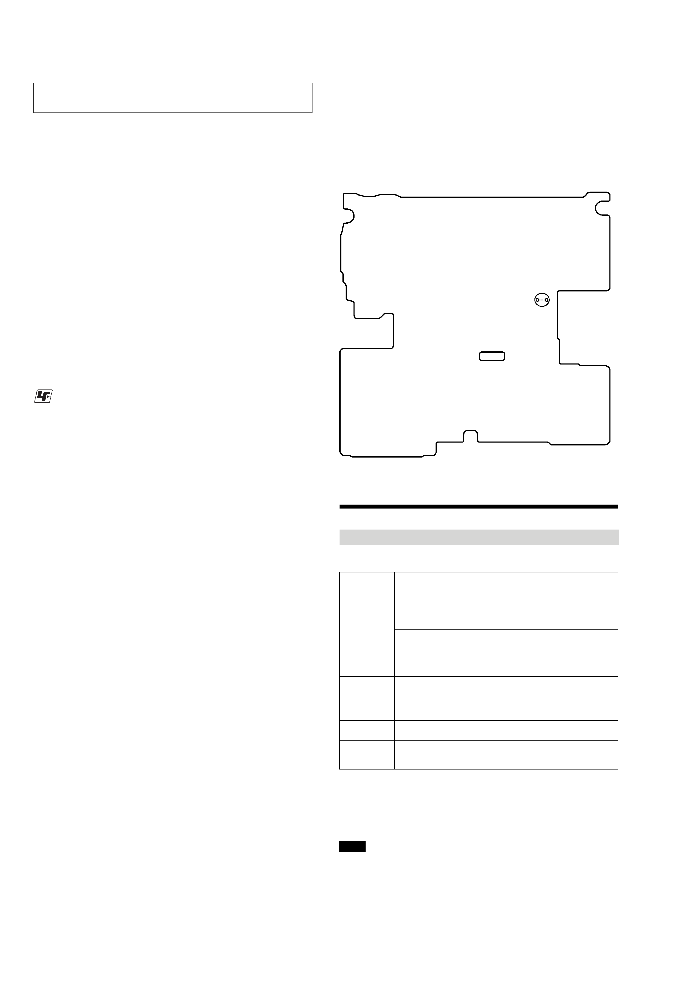
OPERATION CHECK WHEN THE MAIN BOARD IS
REMOVED
In making an operation check with the MAIN board removed from
the set, short the SL894 of the MAIN board with the solder before
starting the operation check.
Note: Be sure to remove the solder used for shortcircuit after the repaire
completed.
MAIN BOARD (Conductor Side)
SL894
UNLEADED SOLDER
Boards requiring use of unleaded solder are printed with the lead-
free mark (LF) indicating the solder contains no lead.
(Caution: Some printed circuit boards may not come printed with
the lead free mark due to their particular size)
: LEAD FREE MARK
Unleaded solder has the following characteristics.
· Unleaded solder melts at a temperature about 40 °C higher
than ordinary solder.
Ordinary soldering irons can be used but the iron tip has to be
applied to the solder joint for a slightly longer time.
Soldering irons using a temperature regulator should be set to
about 350
°C.
Caution: The printed pattern (copper foil) may peel away if
the heated tip is applied for too long, so be careful!
· Strong viscosity
Unleaded solder is more viscou-s (sticky, less prone to flow)
than ordinary solder so use caution not to let solder bridges
occur such as on IC pins, etc.
· Usable with ordinary solder
It is best to use only unleaded solder but unleaded solder may
also be added to ordinary solder.
Providing the required system environment
The following system environment is required in order to use the SonicStage Ver. 3.0/MD
Simple Burner Ver. 2.0 software for the MD Walkman.
This software is not supported by the following environments:
· OSs other than the indicated above
· Personally constructed PCs or operating systems
· An environment that is an upgrade of the original manufacturer-installed operating system
· Multi-boot environment
· Multi-monitor environment
· Macintosh
· We do not ensure trouble-free operation on all computers that satisfy the system requirements.
· The NTFS format of Windows XP/Windows 2000 Professional can be used only with the standard
(factory) settings.
· For Windows 2000 Professional users, install Service Pack 3 or later version before using the
software.
· We do not ensure trouble-free operation of the system suspend, sleep, or hibernation function on all
computers.
System requirements
Computer
IBM PC/AT or Compatible
·CPU: Pentium III 450 MHz or higher
·Hard disk drive space: 200 MB or more (1.5 GB or more is
recommended) (The amount space will vary according to Windows
version and the number of music files stored on the hard disk.)
·RAM: 128 MB or more
Others
·CD drive (capable of digital playback by WDM) (A CD-R/RW drive
is necessary for CD writing)
·Sound Board
·USB port
Operating
System
Factory installed:
Windows XP Media Center Edition 2005/Windows XP Media Center
Edition 2004/Windows XP Media Center Edition/Windows XP
Professional/Windows XP Home Edition/Windows 2000 Professional/
Windows Millennium Edition/Windows 98 Second Edition
Display
High Color (16bit) or higher, 800
600 dots or better (1024
768 dots
or better is recommended)
Others
· Internet access: for Web registration, EMD services and CDDB
·Windows Media Player (version 7.0 or higher) installed for playing
WMA files
Notes
NOTES ON REPLACEMENT OF CSP (CHIP SIZE
PACKAGE) IC
Replacement of MM1690LCBE (IC401), SN761059AZQLR
(IC501), SC901585VAR2 (IC601), CXD2683-225GG (IC801) and
S29PL032J55BFI120A (IC802) used in this set requires a special
tool.
5
MZ-DH10P
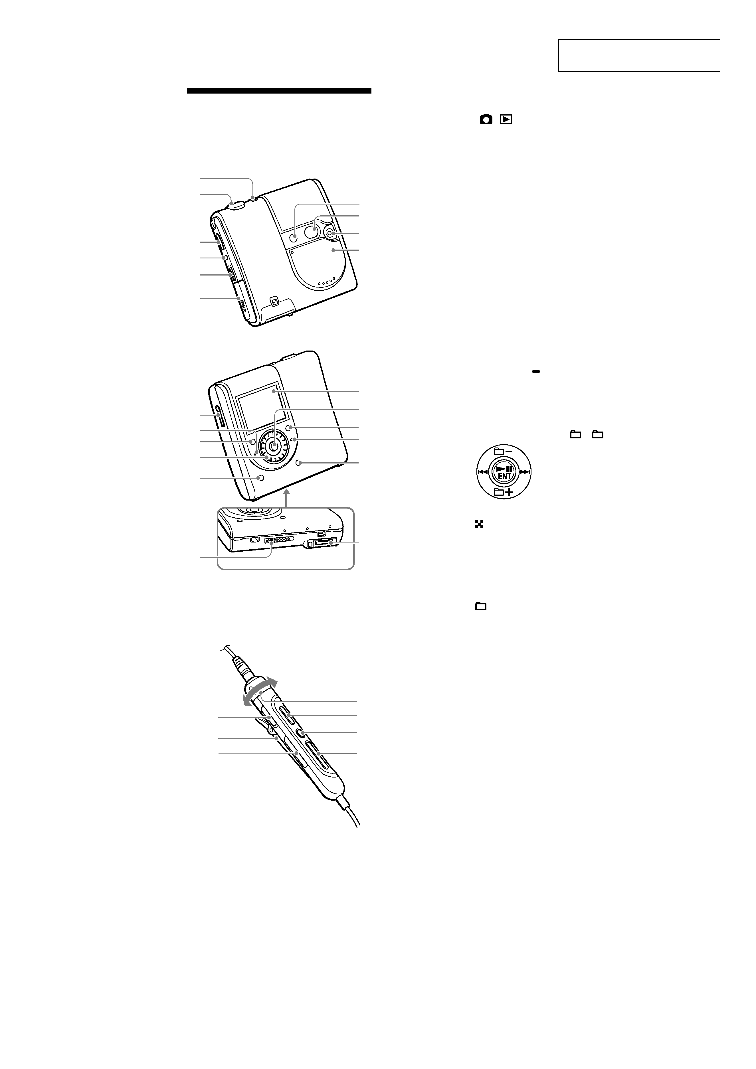
SECTION 2
GENERAL
This section is extracted from
instruction manual.
.