MZ-B50
SERVICE MANUAL
PORTABLE MINIDISC RECORDER
US Model
Canadian Model
AEP Model
Tourist Model
SPECIFICATIONS
Model Name Using Similar Mechanism
NEW
Mechanism Type
MT-MZB50-165
Optical Pick-up Name
LCX-2R
US and foreign patents licensed from Dolby
Laboratories Licensing Corporation
System
Audio playing system
MiniDisc digital audio system
Laser diode properties
Material: GaAlAs
Wavelength:
= 790 nm
Emission duration: continuous
Laser output: less than 44.6
µW
(This output is the value measured at a distance
of 200 mm from the lens surface on the optical
pick-up block with 7 mm aperture.)
Recording and playback time
Maximum 80 minutes (MDW-80, stereo
recording)
Maximum 160 minutes (MDW-80, monaural
recording)
Maximum 74 minutes (MDW-74, stereo
recording)
Maximum 148 minutes (MDW-74, monaural
recording)
Revolutions
400 rpm to 1,800 rpm (CLV)
Error correction
Advanced Cross Interleave Reed Solomon
Code (ACIRC)
Sampling frequency
44.1 kHz
Sampling rate converter
Input: 32 kHz/44.1 kHz/48 kHz
Coding
Adaptive TRansform Acoustic Coding
(ATRAC)
Modulation system
EFM (Eight to Fourteen Modulation)
Number of channels
2 stereo channels
1 monaural channel
Speaker
28 mm (1 1/8 in.) dia.
Frequency response
20 to 20,000 Hz
± 3 dB
Wow and Flutter
Below measurable limit
Inputs
Microphone: stereo mini-jack, 0.35 1.38 mV
Line in: stereo mini-jack, 69 194 mV
Optical (Digital) in: optical (digital) mini-jack
Outputs
i
: stereo mini-jack
Headphones/earphones: 5 mW + 5 mW
Speaker: 300 mW
Continued on next page
Ver 1.1 2001.03
With SUPPLEMENT-1
(9-927-952-83)
9-927-952-12
2001C0200-1
© 2001.3
Sony Corporation
Audio Entertainment Group
General Engineering Dept.

2
1.
SERVICING NOTES 3
2.
GENERAL
4
3.
DISASSEMBLY
3-1. Panel (Lower) ASSY
6
3-2. Main Board, Sled Control Board
6
3-3. Panel (Upper Lid) ASSY
7
3-4. Key Board Unit 7
3-5. BATT Board, DC Jack Board
8
3-6. Mechanism Deck 8
3-7. Optical Pick-up 9
4.
TEST MODE
10
5.
ELECTRICAL ADJUSTMENTS 17
6.
DIAGRAMS
6-1. Explanation of IC Terminals
22
6-2. Block Diagram Main Section (1/3) 29
6-3. Block Diagram Main Section (2/3) 31
6-4. Block Diagram Main Section (3/3) 33
6-5. Printed Wiring Boards Main Section (1/2)
35
6-6. Printed Wiring Boards Main Section (2/2)
37
6-7. Printed Wiring Boards Battery Section
39
6-8. Schematic Diagram Main Section (1/4)
41
6-9. Schematic Diagram Main Section (2/4)
43
6-10. Schematic Diagram Main Section (3/4)
45
6-11. Schematic Diagram Main Section (4/4)
47
7.
EXPLODED VIEWS
7-1. Panel (Lower) Section
55
7-2. Panel Upper Lid Section
56
7-3. Cabinet (Belt) Section
57
7-4. Mechanism Deck Setion (MT-MZB50-165)
58
8.
ELECTRICAL PARTS LIST
59
SAFETY-RELATED COMPONENT WARNING!!
COMPONENTS IDENTIFIED BY MARK 0 OR DOTTED LINE
WITH MARK 0 ON THE SCHEMATIC DIAGRAMS AND IN THE
PARTS LIST ARE CRITICAL TO SAFE OPERATION.
REPLACE THESE COMPONENTS WITH SONY PARTS WHOSE
PART NUMBERS APPEAR AS SHOWN IN THIS MANUAL OR IN
SUPPLEMENTS PUBLISHED BY SONY.
Flexible Circuit Board Repairing
· Keep the temperature of the soldering iron around 270
°C during
repairing.
· Do not touch the soldering iron on the same conductor of the
circuit board (within 3 times).
· Be careful not to apply force on the conductor when soldering or
unsoldering.
Notes on chip component replacement
· Never reuse a disconnected chip component.
· Notice that the minus side of a tantalum capacitor may be dam-
aged by heat.
TABLE OF CONTENTS
CAUTION
Use of controls or adjustments or performance of procedures
other than those specified herein may result in hazardous
radiation exposure.
General
Power requirements
DC 3V
Two LR6 (size AA) alkaline batteries
Battery operation time
Battery life1) (EIAJ2))
Batteries
Recording
Playback
Two LR6 (size AA)
Approx.
Approx.
Sony alkaline dry batteries
6 hours
18 hours
1) The battery life may be shorter due to operating
conditions, the temperature of the location, and
varieties of batteries.
2) Measured in accordance with the EIAJ
(Electronic Industries Association of Japan)
standard.
3) When using LR6 (SG) Sony "STAMINA"
alkaline dry batteries (produced in Japan).
4) To prevent interrupted recording due to drained
batteries, use new batteries for recording
operations.
5) When played using the built-in speaker.
Dimensions
Approx. 88.0
× 28.0 × 121.4 mm (w/h/d)
(3 1/2
× 1 1/8 × 4 7/8 in.) not incl. projecting parts
and controls.
Mass
Approx. 240 g (8.4 oz)
Supplied accessories
Headphones/earphones with a remote control (1)
Sony LR6 (size AA) dry batteries (2)
Carrying pouch (1)
Hand strap (1)
Design and specifications are subject to change without notice.
3
NOTES ON HANDLING THE OPTICAL PICK-UP
BLOCK OR BASE UNIT
The laser diode in the optical pick-up block may suffer electrostatic
break-down because of the potential difference generated by the
charged electrostatic load, etc. on clothing and the human body.
During repair, pay attention to electrostatic break-down and also
use the procedure in the printed matter which is included in the
repair parts.
The flexible board is easily damaged and should be handled with
care.
NOTES ON LASER DIODE EMISSION CHECK
Never look into the laser diode emission from right above when
checking it for adjustment. It is feared that you will lose your sight.
NOTES ON HANDLING THE OPTICAL PICK-UP BLOCK
(LCX-2R)
The laser diode in the optical pick-up block may suffer electrostatic
break-down easily. When handling it, perform soldering
bridge to the laser-tap on the flexible board. Also perform measures
against electrostatic break-down sufficiently before the operation.
The flexible board is easily damaged and should be handled with
care.
OPTICAL PICK-UP FLEXIBLE BOARD
SECTION 1
SERVICING NOTES
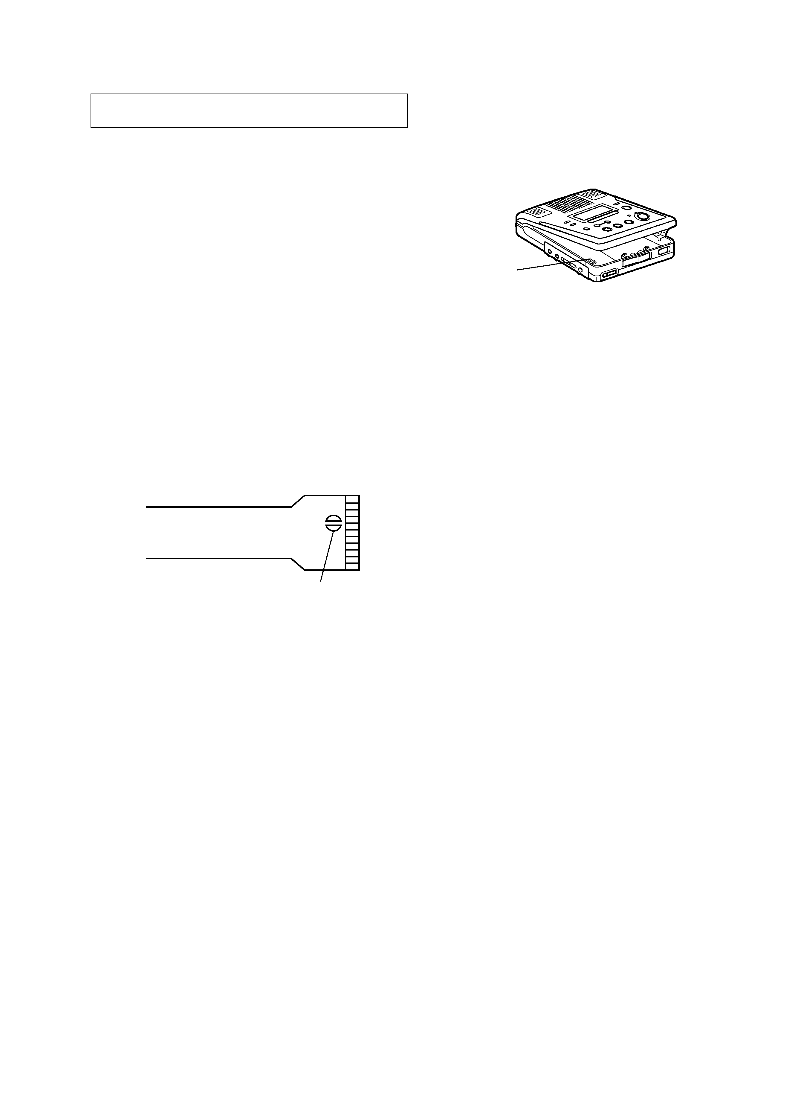
· When repairing this device with the power on, if you remove the
MAIN board or open the upper panel assy, this device stops work-
ing.
In this case, you can work without the device stopping by fasten-
ing the hook of the open/close detect switch (S801).
· This set is designed to perform automatic adjustment for each
adjustment and write its value to EEPROM. Therefore, when
EEPROM (IC802) has been replaced in service, be sure to per-
form automatic adjustment and write resultant values to the new
EEPROM.
(Refer to Section 5 Electrical Adjustment. (page 17))
· Replacement of CXD2660GA (IC502) and CXR701080-020GA
(IC801) used in this set requires a special tool.
laser-tap
S801
4
SECTION 2
GENERAL
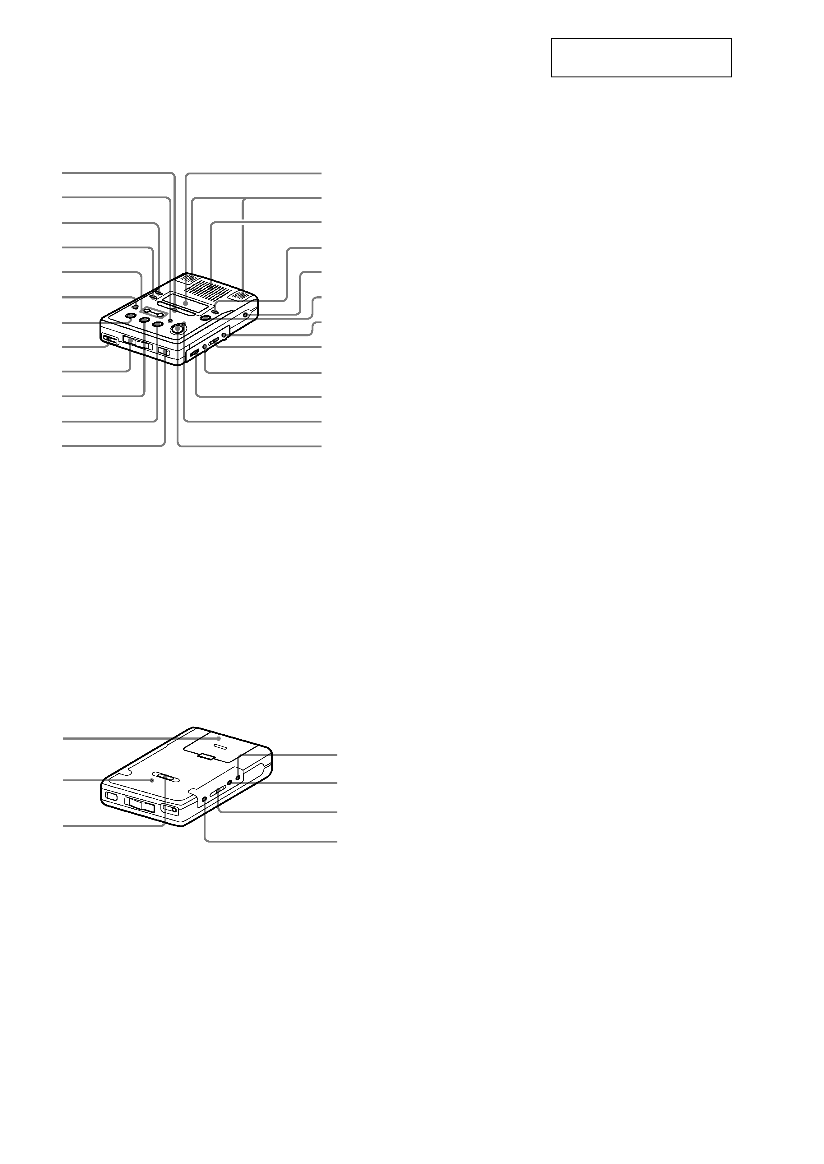
LOCATION AND FUNCTION OF CONTROLS
Front of the recorder
Back of the recorder
This section is extracted from
instruction manual.
1
2
3
4
5
6
7
8
9
0
qa
qs
qd
qf
qg
qh
qj
qk
ql
w;
wa
ws
wd
wf
1 EASY SEARCH +/ buttons
2 VOR indicator
3 PLAY MODE button
4 DISPLAY button
5
.REVIEW/AMS/>CUE/AMS
(search /AMS) button
6 FAST PB button
7
x STOP button
8 i (headphones/earphones) jack
9 OPEN switch
0
N PLAY (play) button
qa
X PAUSE button
qs HOLD switch
qd Display window
qf Microphones
qg Speaker
qh EDIT/ENTER button
qj DC IN 3V jack
qk TRACK MARK button
ql ERASE button
w; REC MODE switch
wa VOR button
ws VOL control
wd REC indicator
wf
z REC button
2
1
3
7
6
5
4
1 Battery compartment
2 CLOCK SET button
3 SYNCHRO REC (synchro-recording)
switch
4 MIC (PLUG IN POWER) jack
5 LINE IN (OPTICAL) jack
6 MIC SENS switch
7 MEGA BASS button
5
1
2
9
0
qj
qs
qd
3
4
5
6
7
8
qa
qf
qg
qh
1
2
3
4
5
7
6
8
9
0
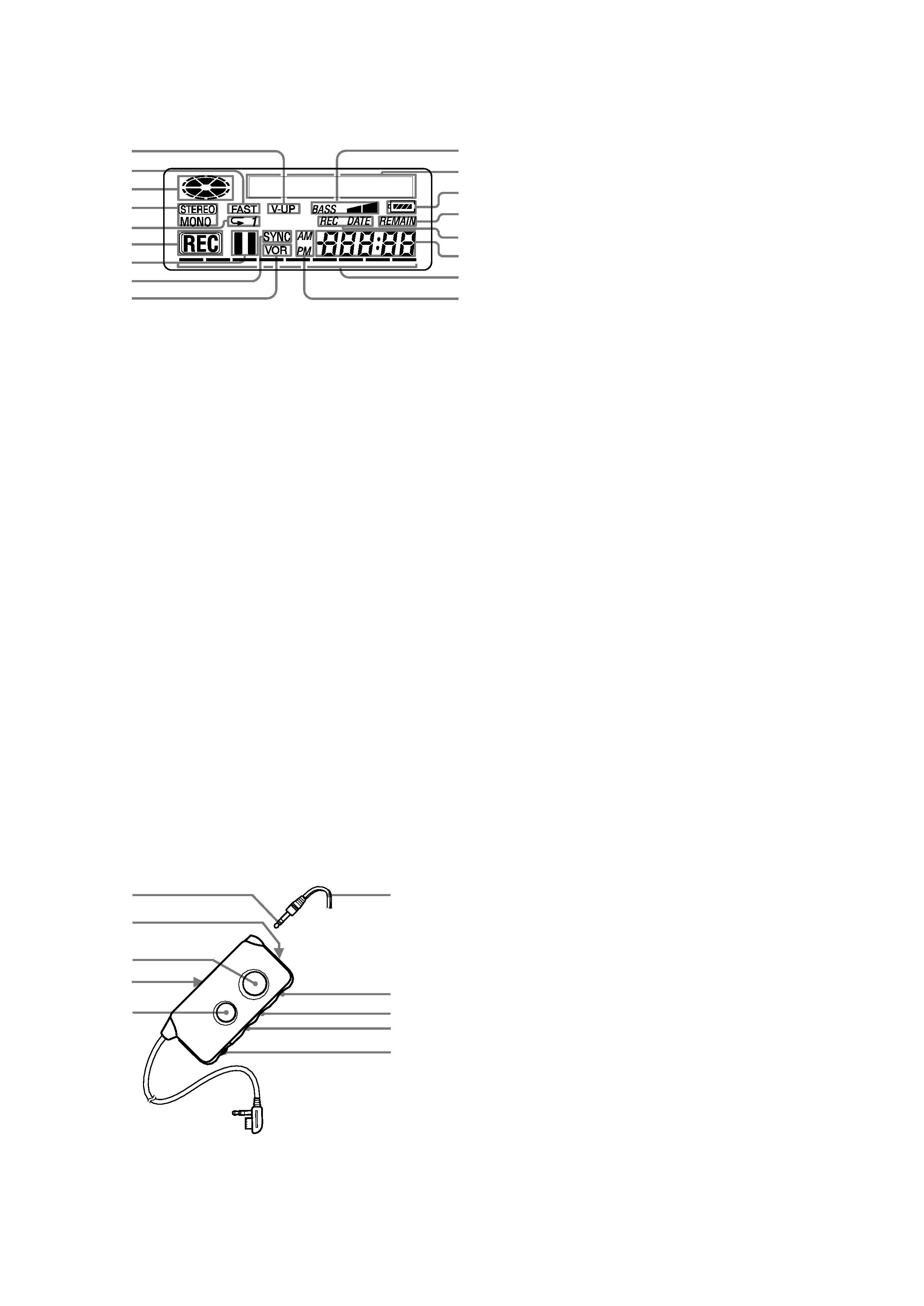
1 V-UP indication
2 Fast Playback indication
3 Disc indication
Shows that the disc is rotating for recording,
playing or editing an MD.
4 STEREO (stereo)/MONO (monaural) indication
5 Play mode indication
6 REC indication
Lights up while recording. When flashing,
the recorder is in record standby mode.
7 Pause indication
8 SYNC (synchro-recording) indication
9 VOR indication
0 Mega Bass indication
qa Character information display
Displays the disc and track names, date,
error messages, track numbers, etc.
qs Battery indication
qd REMAIN (remaining time/tracks) indication
Lights up along with the remaining time of the track,
the remaining time of the MD, or the remaining number
of tracks.
qf REC DATE (recorded/current date) indication
Lights up along with the date and time he MD was
recorded. When only " DATE" lights up, the current
date and time are displayed.
qg Time display
qh Level meter
Shows the volume of the MD being played or recorded.
qj AM/PM indication
1 Stereo mini plug
2 V-UP button
3 TRACK MARK button
4 HOLD switch
Slide to lock the controls of the remote control.
5
X (pause) button
6 Headphones/earphones
7
x (stop) button
8
>N buttons
9
.REVIEW/AMS
0 VOL control
The display window
The headphones/earphones with a remote control