SERVICE MANUAL
COMPACT DISC MINIDISC DECK
US Model
Canadian Model
AEP Model
UK Model
E Model
SPECIFICATIONS
MXD-D40
US and foreign patents licensed from Dolby
Laboratories Licensing Corporation.
Photo: Gold type
CD player section
System
Compact Disc digital audio system
Laser
Semiconductor laser (
= 780 nm)
Emission duration: continuous
Laser output
Less than 44.6 µW*
* This output is the value measured at a
distance of 200 mm from the objective
lens surface on the Optical Pick-up
Block with 7 mm aperture.
Frequency response
5 to 20,000 Hz ±0.5 dB
Signal-to-noise ratio
More than 98 dB
Wow and flutter
Below measurable limit
MD deck section
System
MiniDisc digital audio system
Disc
MiniDisc
Laser
Semiconductor laser (
= 780 nm)
Emission duration: continuous
Laser output
Less than 44.6 µW*
* This output is the value measured at a
distance of 200 mm from the objective
lens surface on the Optical Pick-up
Block with 7 mm aperture.
Laser diode properties
Material: GaAlAs
Revolutions (CLV)
800 rpm to 1,800 rpm
Error correction
Advanced Cross Interleave Reed
Solomon Code (ACIRC)
Sampling frequency
44.1 kHz
Coding
Adaptive TRansform Acoustic Coding
(ATRAC)/ATRAC 3
Modulation system
EFM (Eight-to-Fourteen Modulation)
Number of channels
2 stereo channels
Frequency response
5 to 20,000 Hz ±0.5 dB
Signal-to-noise ratio
Over 98 dB during playback
Wow and flutter
Below measurable limit
Inputs
Jack type Input
impedance
Rated
input
Minimum
input
ANALOG IN
Phono
jacks
47 kilohms
500 mVrms 125 mVrms
DIGITAL
OPTICAL IN
Square
optical
connector
jack
Optical wave
length:
660 nm
----
Ver. 1.2 2005.03
Model Name Using Similar Mechanism
MXD-D5C
MD Mechanism Type
MDM-7X2A
Optical Pick-up Name
KMS-262A
Model Name Using Similar Mechanism
MXD-D4
CD Mechanism Type
CDM55B-21BD53
Base Unit Name
BU-21BD53
Optical Pick-up Name
OP Assy (A-MAX.2)
MD
Section
CD
Section
Continued on next page
9-929-578-13
2005C05-1
© 2005.03
Sony Corporation
Audio Group
Published by Sony Engineering Corporation

2
MXD-D40
General
Power requirements
Where purchased
Power requirements
U.S.A. and Canada
120 V AC, 60 Hz
Europe
220 - 230 V AC, 50/60 Hz
Certain countries in Asia
220 - 240 V AC, 50/60 Hz
Other countries
110 - 120 or 220 - 240 V AC
selectable, 50/60 Hz
Power consumption
22 W (less than 1 W at standby)
Dimensions (approx.) (w/h/d) incl. projecting parts and controls
430
× 120 × 290 mm
Mass (approx.)
4.7 kg
Supplied accessories
Design and specifications are subject to change without
notice.
· Audio connecting cords (2)
· Remote commander (remote) (1)
· Sony R6 (size-AA) batteries (2)
· Power plug adaptor (1) (Singaporian model only)
Outputs
Jack type
Rated output
Load impedance
PHONES
Stereo phone
jack
10 mW
32 ohms
ANALOG
OUT
Phono jacks
2 Vrms
(at 50 kilohms)
Over 10 kilohms
ATTENTION AU COMPOSANT AYANT RAPPORT
À LA SÉCURITÉ!
LES COMPOSANTS IDENTIFIÉS PAR UNE MARQUE 0
SUR LES DIAGRAMMES SCHÉMATIQUES ET LA LISTE
DES PIÈCES SONT CRITIQUES POUR LA SÉCURITÉ
DE FONCTIONNEMENT. NE REMPLACER CES COM-
POSANTS QUE PAR DES PIÈCES SONY DONT LES
NUMÉROS SONT DONNÉS DANS CE MANUEL OU
DANS LES SUPPLÉMENTS PUBLIÉS PAR SONY.
SAFETY-RELATED COMPONENT WARNING!!
COMPONENTS IDENTIFIED BY MARK 0 OR DOTTED
LINE WITH MARK 0 ON THE SCHEMATIC DIAGRAMS
AND IN THE PARTS LIST ARE CRITICAL TO SAFE
OPERATION. REPLACE THESE COMPONENTS WITH
SONY PARTS WHOSE PART NUMBERS APPEAR AS
SHOWN IN THIS MANUAL OR IN SUPPLEMENTS PUB-
LISHED BY SONY.
3
MXD-D40
SELF-DIAGNOSIS FUNCTION
The self-diagnosis function consists of error codes for customers which are displayed automatically when errors occur, and error codes
which show the error history in the test mode during servicing. For details on how to view error codes for the customer, refer to the
following box in the instruction manual. For details on how to check error codes during servicing, refer to the following "Procedure for
using the Self-Diagnosis Function (Error History Display Mode)".
PROCEDURE FOR USING THE SELF-DIAGNOSIS FUNCTION (ERROR HISTORY DISPLAY MODE)
Note: Perform the self-diagnosis function in the "error history display mode" in the test mode. The following describes the least required procedure. Be
careful not to enter other modes by mistake. If you set other modes accidentally, press the [MENU/NO] button to exit the mode.
1. Press the x (CD), x (MD) and [YES] buttons at the same time.
2. Press the [
AMS
] (MD) knob and x (MD) button to display " <To Normal> 0".
3. Turn the [
AMS
] (MD) knob and when " <MD Test> 5" is displayed, press the [
AMS
] (MD) knob.
4. Turn the [
AMS
] (MD) knob and when "[Service]" is displayed, press the [YES] button.
5. Turn the [
AMS
] (MD) knob to display "Err Display".
6. Press the [YES] button to sets the error history mode and displays "op rec tm".
7. Select the contents to be displayed or executed using the [
AMS
] (MD) knob.
8. Press the [
AMS
] (MD) knob to display or execute the contents selected.
9. Press the [
AMS
] (MD) knob another time returns to step 6.
10. Press the [MENU/NO] button to display "Err Display" and release the error history mode.
11. To release the test mode, press the ?/1 button to display " <MD Test> 5".
12. To turn the power OFF, turn the [
AMS
] (MD) knob and when " <Initial> 8" displayed, press the [
AMS
] (MD)
knob.
lL
lL
lL
lL
lL
lL
lL
lL
l
L
lL
Self-Diagnosis Function
The deck has a self-diagnosis display. This function shows a three- or five-digit display (a combination of a letter and
figures) and the corresponding message, so you can check the deck's condition.
If such a display appears, check the following table in order to resolve the problem.
Should any problem persist, consult your nearest Sony dealer.
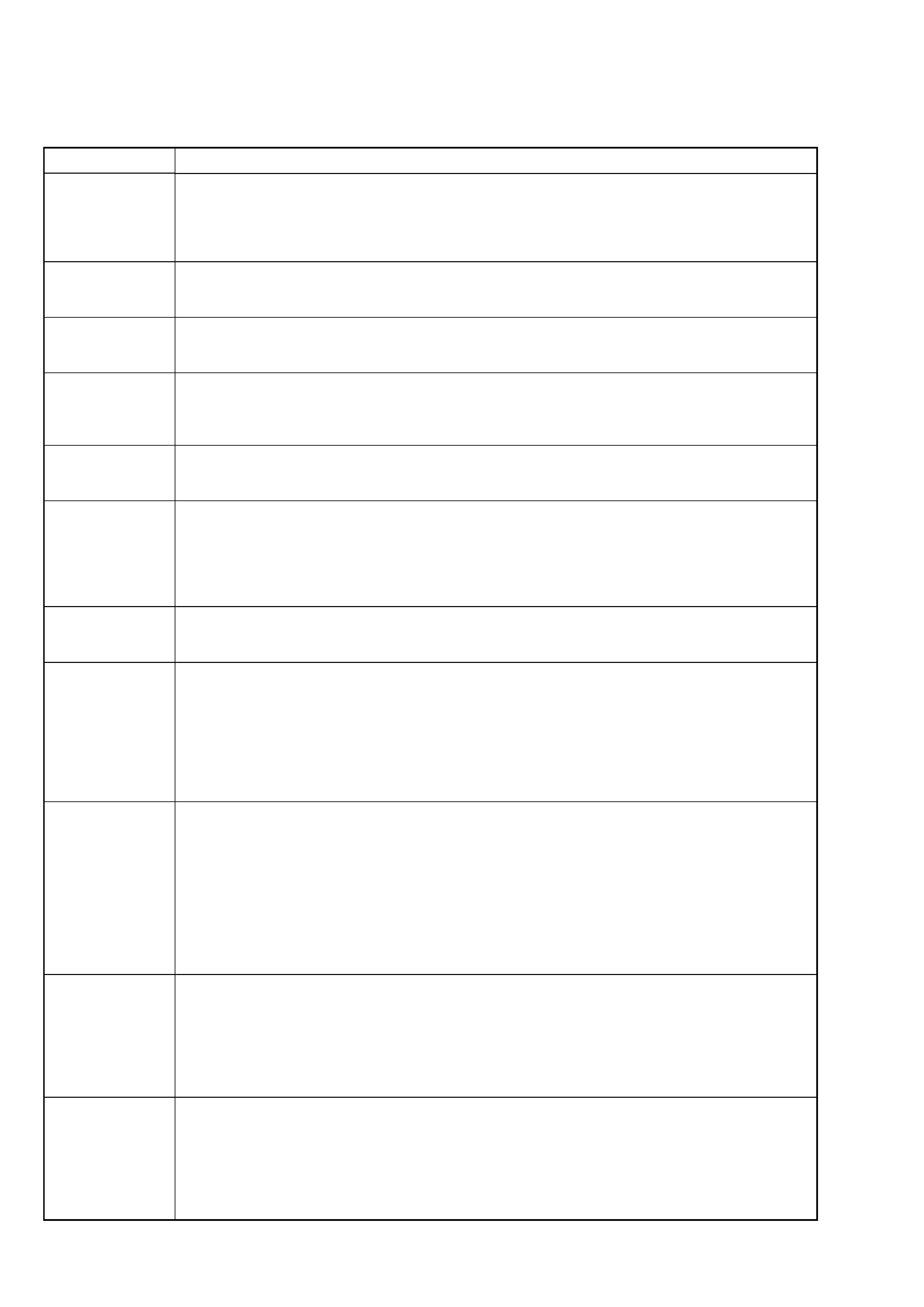
Three- or five-digit display/Message
Cause/Remedy
C11/Protected
The inserted MD is record-protected.
, Take out the MD, and close the record-protect tab.
C13/REC Error
The recording was not made properly.
, Set the deck in a stable place, and repeat the recording procedure.
The inserted MD is dirty (with smudges, fingerprints, etc.), scratched, or not up to
standards.
, Replace the disc, and repeat the recording procedure.
C14/TOC Error
The deck could not read the TOC of the MD properly.
, Insert another disc.
, If possible, erase all tracks on the MD using the All Erase Function.
While recording from a digital component connected through the DIGITAL
OPTICAL IN connector, the digital connecting cable was unplugged or the digital
component turned off.
, Connect the cable or turn the digital component back on.
C12/Cannot Copy
An attempt was made to play a disc that is not compatible with this deck (CD-
ROM, MD data disc, etc.).
, Replace the disc.
C13/Read Error
The deck could not read the TOC of the MD properly.
, Eject the disc, then insert it again.
C41/Cannot Copy
The digitally dubbed material cannot be recorded digitally.
C71/Din Unlock
A moment's lighting is due to the signals of the digital program being recorded.
This does not affect the recorded material.
E0001/MEMORY NG
There is an error in the internal data that the deck needs in order to operate.
, Consult your nearest Sony dealer.
E0101/LASER NG
There ia a problem with the optical pick-up.
, The optical pick-up may have failed. Consult your nearest Sony dealer.
4
MXD-D40
ITEMS OF ERROR HISTORY MODE ITEMS AND CONTENTS
Selecting the Test Mode
Display
Details of History
op rec tm
Cumulative recording time is displayed.
When cumulative recording time is over 1 minute, the hour and minute are displayed as they are.
When it is under 1 minute, "Under 1 min" is displayed.
The displayed time shows how long the laser is in high power state.
It is about one fourth the actual recording time.
op play tm
Cumulative playing time is displayed.
When cumulative playing time is over 1 minute, the hour and minute are displayed as they are.
When it is under 1 minute, "Under 1 min" is displayed.
spdl rp tm
Cumulative spindle motor running time is displayed.
When cumulative spindle motor run time is over 1 minute, the hour and minute are displayed as they are.
When it is under 1 minute, "Under 1 min" is displayed.
retry err
Displays the total number of retries during recording and number of retry errors during play.
Displayed as "rss pss".
"r" indicates the retries during recording while "p" indicates the retry errors during play.
The number of retries and retry errors are displayed in hexadecimal digits from 00 to FF.
total err
Displays the total number of errors.
Displayed as "total ss".
The number of errors is displayed in hexadecimal digits from 00 to FF.
err history
Displays the 10 latest errors.
Displayed as "0s ErrCd@@".
s indicates the history number. The smaller the number, the more recent is the error. (00 is the latest).
@@ indicates the error code.
Refer to the following table for the details. The error history can be switched by turning the [
AMS
]
(MD) knob.
retry adrs
Displays the past five retry addresses.
Displays "ss ADRS ssss", ss is the history number, ssss is the cluster with the retry error.
Select the error history number using the [
AMS
] knob.
er refresh
Mode to clear the error history and retry address history.
[Operating method]
1) Press [
AMS
] (MD) knob when "er refresh" is displayed.
2) The display will change to "er refresh?", and then press [YES] button.
The operation is over if "Complete!" is displayed.
After this mode was executed, check the following:
· The data have been cleared.
· Perform the recording and playing to check that the mechanism operates normally.
tm refresh
Mode to clear the "op rec tm" and "op play tm" histories.
These histories serve as approximate indications of when to replace the optical pick-up. If the optical pick-up
has been replaced, perform this operation and clear the history.
[Operating method]
1) Press [
AMS
] (MD) knob when "tm refresh" is displayed.
2) The display will change to "tm refresh?", and then press [YES] button.
The operation is over if "Complete!" is displayed.
After this mode was executed, check the following:
· The data have been cleared.
· Perform the recording and playing to check that the mechanism operates normally.
op change
Mode to clear cumulative time of "op rec tm" and "op play tm".
These historical data are used to determine the timing when the optical pick-up is to be replaced. When the
optical pick-up was replaced, perform this operation to clear historical data.
[Operating method]
1) Press [
AMS
] (MD) knob when "op change" is displayed.
2) The display will change to "op chang?", and then press [YES] button.
The operation is over if "Complete!" is displayed.
spdl change
Mode to clear cumulative time of "spdl rp tm".
This historical data is used to determine the timing when the spindle motor is to be replaced. When the spindle
motor was replaced, perform this operation to clear historical data.
[Operating method]
1) Press [
AMS
] (MD) knob when "spdl change" is displayed.
2) The display will change to "spdl chang?", and then press [YES] button.
The operation is over if "Complete!" is displayed.
lL
lL
lL
lL
lL
lL
5
MXD-D40
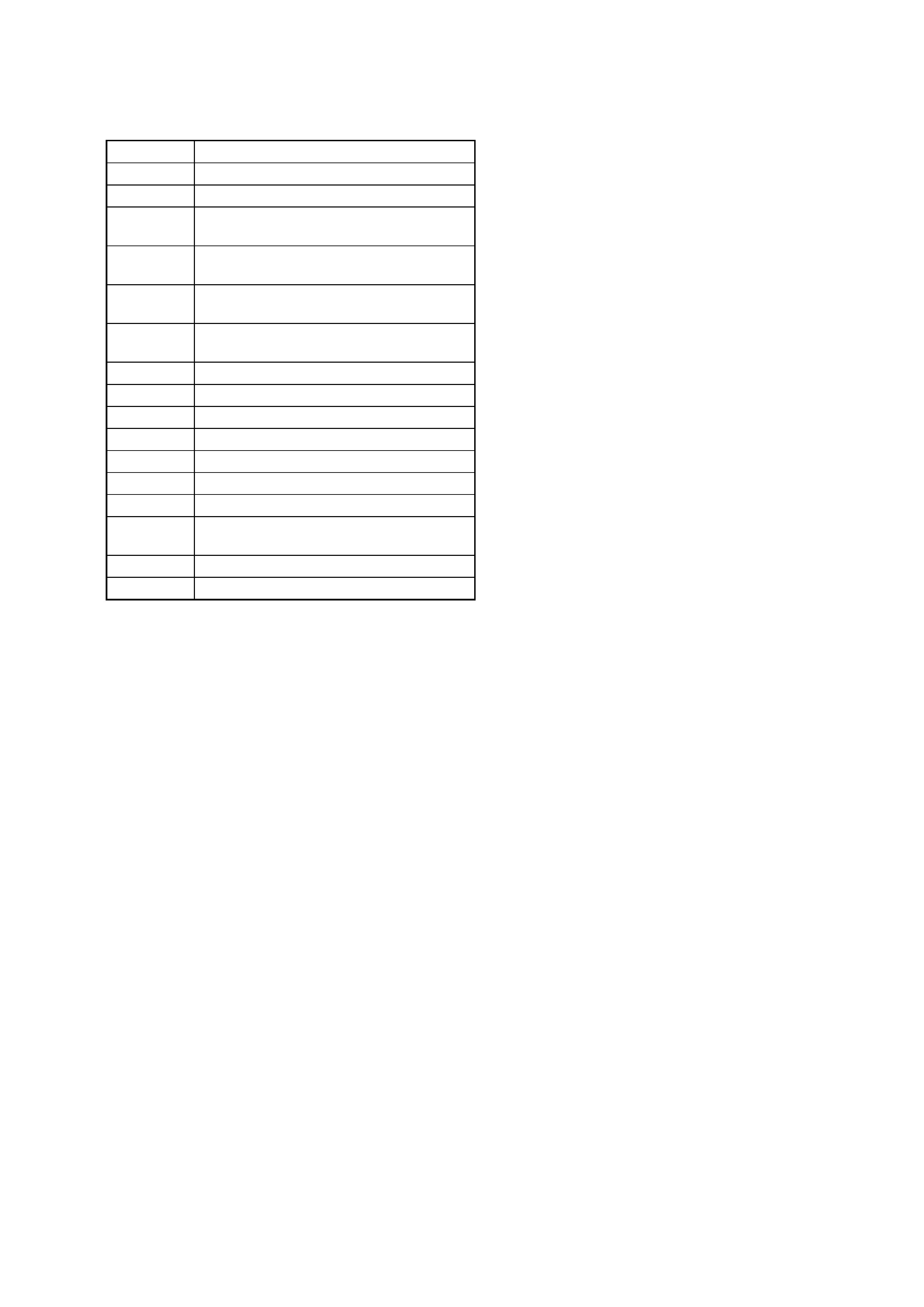
Error Code
Details of Error
10
Loading failed
12
Loading switch combination is illegal
20
Head of PTOC could not be read within the
specified time
21
Head of PTOC could be read but its content is
erroneous
22
Access to UTOC could not be made within the
specified time
23
UTOC could be not read within the specified
3time
24
Content of UTOC is erroneous
30
Playing could not start
31
Content of sector is erroneous
40
Cause of retry occurred during normal recording
41
D-RAM overflowed and retry was executed
42
Retry was executed during the writing to TOC
43
S.F editing was interrupted by retry
50
Address could not be read except in access
processing
51
Focusing failed and it is out of control
60
Unlock retry
Table of Error Codes