MVC-FD91
US Model
Canadian Model
AEP Model
UK Model
E Model
Australian Model
Hong Kong Model
Tourist Model
Chinese Model
SERVICE MANUAL
DIGITAL STILL CAMERA
MICROFILM
SPECIFICATIONS
Ver 1.1 2000. 10
With SUPPLEMENT-1
(9-974-119-81)

-- 2 --
SAFETY-RELATED COMPONENT WARNING!!
COMPONENTS IDENTIFIED BY MARK
! OR DOTTED LINE WITH
MARK
! ON THE SCHEMATIC DIAGRAMS AND IN THE PARTS
LIST ARE CRITICAL TO SAFE OPERATION. REPLACE THESE
COMPONENTS WITH SONY PARTS WHOSE PART NUMBERS
APPEAR AS SHOWN IN THIS MANUAL OR IN SUPPLEMENTS
PUBLISHED BY SONY.
ATTENTION AU COMPOSANT AYANT RAPPORT
À LA SÉCURITÉ!
LES COMPOSANTS IDENTIFÉS PAR UNE MARQUE
! SUR LES
DIAGRAMMES SCHÉMATIQUES ET LA LISTE DES PIÈCES SONT
CRITIQUES POUR LA SÉCURITÉ DE FONCTIONNEMENT. NE
REMPLACER CES COMPOSANTS QUE PAR DES PIÈSES SONY
DONT LES NUMÉROS SONT DONNÉS DANS CE MANUEL OU
DANS LES SUPPÉMENTS PUBLIÉS PAR SONY.
1.
Check the area of your repair for unsoldered or poorly-soldered
connections. Check the entire board surface for solder splashes
and bridges.
2.
Check the interboard wiring to ensure that no wires are
"pinched" or contact high-wattage resistors.
3.
Look for unauthorized replacement parts, particularly
transistors, that were installed during a previous repair. Point
them out to the customer and recommend their replacement.
4.
Look for parts which, through functioning, show obvious signs
of deterioration. Point them out to the customer and
recommend their replacement.
5.
Check the B+ voltage to see it is at the values specified.
6.
Flexible Circuit Board Repairing
· Keep the temperature of the soldering iron around 270°C
during repairing.
· Do not touch the soldering iron on the same conductor of the
circuit board (within 3 times).
· Be careful not to apply force on the conductor when soldering
or unsoldering.
SAFETY CHECK-OUT
After correcting the original service problem, perform the following
safety checks before releasing the set to the customer.

-- 3 --
TABLE OF CONTENTS
SERVICE NOTE ····································································· 5
1.
GENERAL
Before using your camera .......................................................... 1-1
Parts identification ..................................................................... 1-1
Basic operations
Preparation ............................................................................. 1-2
1: Charging the battery pack .................................................. 1-2
2: Installing the battery pack .................................................. 1-2
3: Setting the date and time ................................................... 1-3
Recording and playing back images ...................................... 1-3
1: Recording still images ....................................................... 1-3
2: Recording moving images ................................................. 1-4
3: Playing back still images ................................................... 1-4
4: Playing back moving images ............................................. 1-4
Battery life/No. of images that can be recorded/
played back ............................................................................ 1-5
Viewing images using a personal computer .......................... 1-5
Advanced operations
Changing the mode settings ................................................... 1-6
Setting the mode of each item ............................................... 1-6
Using various functions for recording ................................... 1-8
Focusing manually ................................................................. 1-8
Releasing the Steady Shot function ....................................... 1-8
Adjusting the white balance ................................................... 1-8
Using the PROGRAM AE function ....................................... 1-9
Additional information
Charging the lithium battery in the camera ........................... 1-9
Precautions ............................................................................. 1-9
Troubleshooting ................................................................... 1-10
Self-diagnosis display .......................................................... 1-10
Warning messages ............................................................... 1-10
Function guide ..................................................................... 1-11
2.
DISASSEMBLY
2-1.
EVF Block (1), RL-52 Board .......................................... 2-1
2-2.
EVF Block (2) ................................................................. 2-2
2-3.
VF-131 Board .................................................................. 2-2
2-4.
Cabinet (ST) Assembly, FLASH Unit, MA-348 Board .. 2-3
2-5.
LCD Unit, PD-104 Board ................................................ 2-3
2-6.
Lens Block ....................................................................... 2-4
2-7.
CD-207 Board, VP-49 Board, SE-78 Board ................... 2-5
2-8.
FC-67 Board, DD-119 Board .......................................... 2-6
2-9.
PK-45 Board, FDD Block Assembly .............................. 2-7
2-10. Circuit Boards Location .................................................. 2-8
2-11. Flexible Boards Location ................................................ 2-8
3.
BLOCK DIAGRAMS
3-1.
Overall Block Diagram ................................................... 3-1
3-2.
Camera/FDD Interface Block Diagram ........................... 3-5
3-3.
Mode Control Block Diagram ......................................... 3-9
3-4.
LCD Block Diagram ..................................................... 3-13
3-5.
Color EVF Block Diagram ............................................ 3-15
3-6.
Power Block Diagram ................................................... 3-18
4.
PRINTED WIRING BOARDS AND
SCHEMATIC DIAGRAMS
4-1.
Frame Schematic Diagram .............................................. 4-1
4-2.
Printed Wiring Boards and Schematic Diagrams ............ 4-6
· CD-207 (CCD Imager)
Printed Wiring Board ...................................... 4-7
· CD-207 (CCD Imager)
Schematic Diagram ......................................... 4-8
· SE-78 (YAW, Pitch Sensor)
Printed Wiring Board and
Schematic Diagram ......................................... 4-9
· VP-49 (Steady Shot Control)
Schematic Diagram ....................................... 4-12
· VP-49 (Steady Shot Control, Active Prism Actuator
Drive) Printed Wiring Board ....................................... 4-15
· FC-67 (Camera Y/C Process, DRAM Control,
Lens Motor Drive, D/A Converter, Audio A/D.D/A
Converter, FD/System Control, HI Control)
Printed Wiring Board .................................... 4-17
· FC-67 (Camera Y/C Process)(1/7)
Schematic Diagram ....................................... 4-22
· FC-67 (DRAM Control)(2/7)
Schematic Diagram ....................................... 4-25
· FC-67 (Lens Motor Drive)(3/7)
Schematic Diagram ....................................... 4-29
· FC-67 (D/A Converter)(4/7)
Schematic Diagram ....................................... 4-31
· FC-67 (Audio D/A.A/D Converter)(5/7)
Schematic Diagram ....................................... 4-35
· FC-67 (FD/System Control)(6/7)
Schematic Diagram ....................................... 4-37
· RL-52 (Release Switch)
Printed Wiring Board .................................... 4-41
· FC-67 (HI Control)(7/7)
Schematic Diagram ....................................... 4-42
· PK-45 (REC/PB AMP, Motor Drive)(1/4)
Schematic Diagram ....................................... 4-45
· PK-45 (LCD Drive)(2/4)
Schematic Diagram ....................................... 4-49
· PK-45 (Timing Generator)(3/4)
Schematic Diagram ....................................... 4-51
· PK-45 (Mode Switch)(4/4)
Schematic Diagram ....................................... 4-55
· PK-45 (REC/PB AMP, Motor Drive, LCD Drive,
Timing Generator, Mode Switch)
Printed Wiring Board .................................... 4-57
· PD-104 (Back-Light Drive)
Printed Wiring Board and
Schematic Diagram ....................................... 4-62
· MA-348 (MIC AMP, ALC)
Printed Wiring Board and
Schematic Diagram ....................................... 4-65
· VF-131 (LCD Drive, Timing Generator)
Printed Wiring Board .................................... 4-69
· VF-131 (LCD Drive, Timing Generator)(1/2)(2/2)
Schematic Diagram ....................................... 4-71
· DD-119 (DC/DC Converter)
Schematic Diagram ....................................... 4-75
· DD-119 (DC/DC Converter)
Printed Wiring Board .................................... 4-79
· MF Block, ZM Block, SW Block
Schematic Diagram ....................................... 4-82
5.
ADJUSTMENTS
5-1.
Camera Section Adjustment ............................................ 5-1
1-1.
Preparations before Adjustment (Camera Section) ......... 5-1
1-1-1. List of Service Tools ........................................................ 5-1
1-1-2. Preparations ..................................................................... 5-2
1-1-3. Discharging of the flashlight power supply ..................... 5-2
1-1-4. Precaution ........................................................................ 5-4
1.
Setting the Switch ............................................................ 5-4
2.
Order of Adjustments ...................................................... 5-4
3.
Subjects ........................................................................... 5-4
1-2.
Initialization of F, E Page Data ........................................ 5-5
1.
Initializing the F, E Page Data ......................................... 5-5
2.
Modification of F, E Page Data ....................................... 5-5
3.
F Page Table .................................................................... 5-5
4.
E Page Table .................................................................... 5-7

-- 4 --
1-3.
Camera System Adjustments ......................................... 5-10
1.
Picture Frame Setting .................................................... 5-10
2.
HALL Adjustment ......................................................... 5-11
3.
Flange Back Adjustment ............................................... 5-11
4.
Flange Back Check ........................................................ 5-12
5.
Light Level Adjustment ................................................. 5-12
6.
Auto White Balance Standard Data Input ..................... 5-13
7.
Auto White Balance Adjustment ................................... 5-13
8.
Color Reproduction Adjustment .................................... 5-14
9.
White Balance Check .................................................... 5-15
10.
Strobe Light Level Adjustment ..................................... 5-15
11.
Strobe White Balance Adjustment ................................. 5-16
12.
Strobe Light Level and White Balance Check .............. 5-16
13.
Steady Shot Adjustment ................................................ 5-17
13-1. Steady Shot Adjustment (1) ........................................... 5-17
13-2. Steady Shot Adjustment (2) ........................................... 5-18
14.
CCD Defect Compensation ........................................... 5-19
14.
CCD Defect Compensation Check ................................ 5-19
1-4.
Color Electronic Viewfinder System Adjustment .......... 5-20
1.
EVF Initial Data Input ................................................... 5-20
2.
VCO Adjustment (VF-131 board) ................................. 5-21
3.
Bright Adjustment (VF-131 board) ............................... 5-21
4.
Contrast Adjustment (VF-131 board) ............................ 5-22
5.
Backlight Consumption Current Adjustment
(VF-131 board) .............................................................. 5-22
6.
White Balance Adjustment (VF-131 Board) ................. 5-23
1-5.
LCD System Adjustment ............................................... 5-24
1.
LCD Initial Data Input .................................................. 5-24
2.
VCO Adjustment (PK-45 board) ................................... 5-25
3.
D range Adjustment (PK-45 board) ............................... 5-25
4.
Bright Adjustment (PK-45 board) ................................. 5-26
5.
Contrast Adjustment (PK-45 board) .............................. 5-26
6.
Color Adjustment (PK-45 board) .................................. 5-27
7.
V-COM Level Adjustment (PK-45 board) .................... 5-27
8.
V-COM Adjustment (PK-45 board) .............................. 5-28
9.
White Balance Adjustment (PK-45 board) .................... 5-28
1-6.
System Control System Adjustment .............................. 5-29
1.
Battery End Adjustment (FC-67 board) ........................ 5-29
2.
Alignment Check (FDD Unit) ....................................... 5-30
5-2.
Service Mode ................................................................. 5-31
2-1.
Adjustment Remote Commander .................................. 5-31
1.
Using the Adjustment Remote Commander .................. 5-31
2.
Precautions upon using the adjustment remote
commander .................................................................... 5-31
2-2.
Data Process .................................................................. 5-32
2-3.
Service Mode ................................................................. 5-33
1.
Setting the Test Mode .................................................... 5-33
2.
Bit value discrimination ................................................ 5-33
3.
Switch Check (1) ........................................................... 5-33
4.
Switch Check (2) ........................................................... 5-34
5.
Self Diagnosis Log Check ............................................. 5-34
6.
REPAIR PARTS LIST
6-1.
Exploded Views ............................................................... 6-1
6-1-1. Cabinet (RL) Section ....................................................... 6-1
6-1-2. EVF Section .................................................................... 6-2
6-1-3. Cabinet (Front) Section ................................................... 6-3
6-1-4. Cabinet (Rear) Section .................................................... 6-4
6-1-5. LCD Panel Section .......................................................... 6-5
6-1-6. Lens Block Section .......................................................... 6-6
6-2.
Electrical Parts List ......................................................... 6-7
* The color reproduction frame is shown on page 185.
-- 5 --
SERVICE NOTE
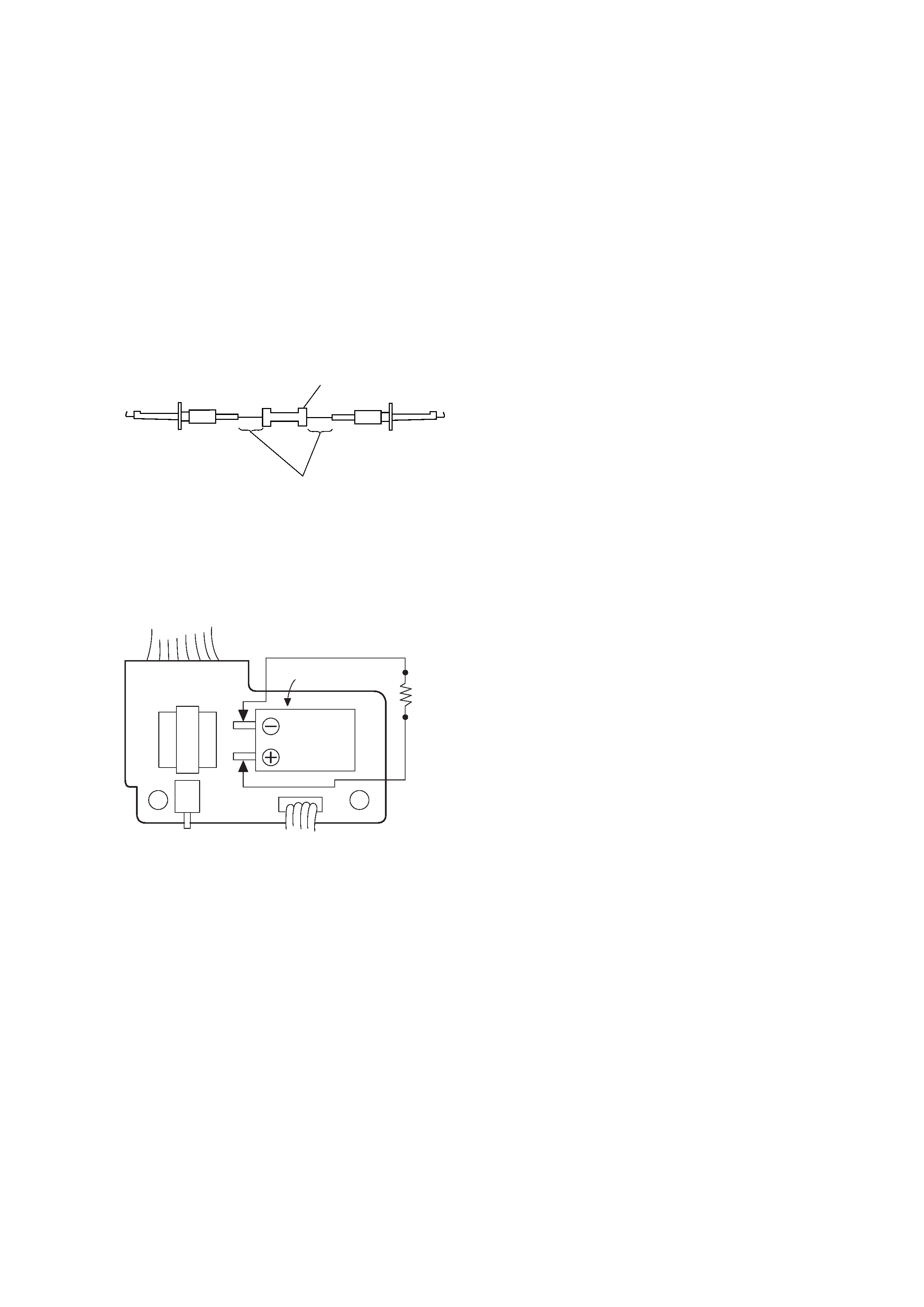
[Discharging of the FLASH unit's charging capacitor]
The charging capacitor of the FLASH unit is charged up to the
maximum 300 V potential.
There is a danger of electric shock by this high voltage when the
battery is handled by hand. The electric shock is caused by the
charged voltage which is kept without discharging when the main
power of the MVC-FD91 is simply turned off. Therefore, the
remaining voltage must be discharged as described below.
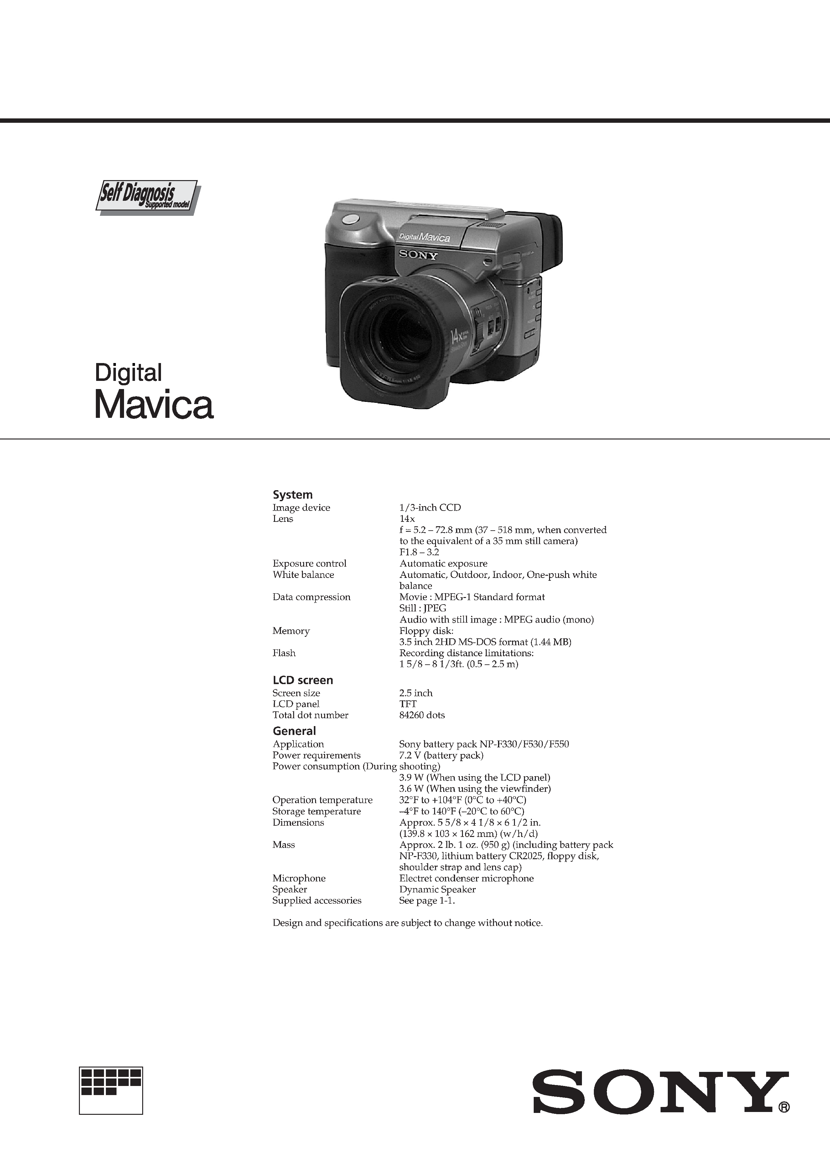
Preparing the Short Jig
To preparing the short jig. a small clip is attached to each end of a
resistor of 1k
/1W (1-215-869-11)
Wrap insulating tape fully around the leads of the resistor to prevent
electrical shock.
Discharging the Capacitor
Short circuits between the positive and the negative terminals of
charged capacitor with the short jig about 10 seconds.
1k
/1W
Wrap insulating tape.
Capacitor
FLASH UNIT
Short jig