MVC-FD85/FD90
US Model
Canadian Model
AEP Model
UK Model
E Model
Australian Model
Hong Kong Model
Chinese Model
Tourist Model
Japanese Model
MVC-FD85/FD90
Korea Model
MVC-FD90
Brazilian Model
MVC-FD85
SERVICE MANUAL
DIGITAL STILL CAMERA
This service manual contains information
for japanese model as well.
Level 2
SPECIFICATIONS
On the FC-72 board
This service manual provides the information that is premised the circuit board
replacement service and not intended repair inside the FC-72 board.
Therefore, schematic diagram, printed wiring board and electrical parts list of
the FC-72 board are not shown.
The following pages are not shown.
Block diagram ............................... Page 3-9 to 3-18
Schematic diagram ....................... Page 4-9 to 4-26
Printed wiring board ..................... Page 4-27 to 4-30
Electrical parts list ........................ Page 6-7 to 6-14
The above-described information is shown in service manual Level 3.
Photo: MVC-FD90
Ver 1.2 2001. 08

-- 2 --
SAFETY-RELATED COMPONENT WARNING!!
COMPONENTS IDENTIFIED BY MARK 0 OR DOTTED LINE WITH
MARK 0 ON THE SCHEMATIC DIAGRAMS AND IN THE PARTS
LIST ARE CRITICAL TO SAFE OPERATION. REPLACE THESE
COMPONENTS WITH SONY PARTS WHOSE PART NUMBERS
APPEAR AS SHOWN IN THIS MANUAL OR IN SUPPLEMENTS
PUBLISHED BY SONY.
ATTENTION AU COMPOSANT AYANT RAPPORT
À LA SÉCURITÉ!
LES COMPOSANTS IDENTIFÉS PAR UNE MARQUE 0 SUR LES
DIAGRAMMES SCHÉMATIQUES ET LA LISTE DES PIÈCES SONT
CRITIQUES POUR LA SÉCURITÉ DE FONCTIONNEMENT. NE
REMPLACER CES COMPOSANTS QUE PAR DES PIÈSES SONY
DONT LES NUMÉROS SONT DONNÉS DANS CE MANUEL OU
DANS LES SUPPÉMENTS PUBLIÉS PAR SONY.
1.
Check the area of your repair for unsoldered or poorly-soldered
connections. Check the entire board surface for solder splashes
and bridges.
2.
Check the interboard wiring to ensure that no wires are
"pinched" or contact high-wattage resistors.
3.
Look for unauthorized replacement parts, particularly
transistors, that were installed during a previous repair. Point
them out to the customer and recommend their replacement.
4.
Look for parts which, through functioning, show obvious signs
of deterioration. Point them out to the customer and
recommend their replacement.
5.
Check the B+ voltage to see it is at the values specified.
6.
Flexible Circuit Board Repairing
· Keep the temperature of the soldering iron around 270°C
during repairing.
· Do not touch the soldering iron on the same conductor of the
circuit board (within 3 times).
· Be careful not to apply force on the conductor when soldering
or unsoldering.
SAFETY CHECK-OUT
After correcting the original service problem, perform the following
safety checks before releasing the set to the customer.
Table for differences of function
Model
Destination
CCD imager size
Lens Optical
Manual foucs
LANC jack
CD board
FC board
PD board
FU board
MVC-FD85
US, CND, AEP, UK, E,
AUS, HK, CN, JE, BR, J
1/2.7 inch
3
×
CD-248
FC-72
PD-52
FU-146
MVC-FD90
US, CND, AEP, UK, E,
AUS, HK, CN, JE, KR, J
1/3.6 inch
8
×
a
a
CD-246
FC-72
PD-50
FU-140
Remark
a: with CN401 of FC-72 board.
a: with J782 of PK-50 board.
Abbreviation
CND: Canadian mode
HK:
Hong Kong model
AUS:
Austrarian model
KR:
Korea model
BR:
Brazilian model
CN:
Chinese model
JE:
Tourist model
J:
Japanese model

-- 3 --
TABLE OF CONTENTS
SERVICE NOTE ····································································· 5
1.
GENERAL
Getting started
Identifying the parts ······························································· 1-1
Preparing the power supply ··················································· 1-2
Starting the date and time ······················································ 1-3
Inserting a floppy disk ··························································· 1-3
Basic operations
Recording still images ··························································· 1-3
Recording moving images ····················································· 1-4
Playing back still images ······················································· 1-5
Playing back moing images ··················································· 1-5
Viewing images using a personal computer ·························· 1-5
Image file storage destinations and image file names ··········· 1-6
Advanced operations
Before performing advanced operations ································ 1-6
Additional information
Precautions ··········································································· 1-13
Using your camera abroad ··················································· 1-13
Troubleshooting ··································································· 1-13
Warning and notice messages ·············································· 1-14
Self-diagnosis display ·························································· 1-14
LCD screen indicators ························································· 1-15
2.
DISASSEMBLY
2-1.
CABINET (REAR) BLOCK ASSEMBLY ····················· 2-1
2-2.
FC-72 BOARD, FLOPPY DISK DRIVE ······················· 2-2
2-3.
LENS BLOCK ASSEMBLY ··········································· 2-3
2-4.
LCD, PK-50/52 BOARD ················································· 2-4
2-5.
FLASH UNIT, FU-140/146 BOARD ······························ 2-5
2-6.
DC-IN CONNECTOR, MICROPHONE UNIT ·············· 2-6
2-7.
HINGE ASSEMBLY,
BATTERY TERMINAL BOARD ··································· 2-6
2-8.
EJECT BUTTON SECTION ·········································· 2-7
2-9.
FOCUS STEPPING MOTOR,
ZOOM STEPPING MOTOR,
ND-METER (MVC-FD90) ············································· 2-7
2-10. FOCUS MOTOR UNIT,
ZOOM MOTOR UNIT (MVC-FD85) ···························· 2-7
2-11. CIRCUIT BOARDS LOCATION ··································· 2-8
2-12. FLEXIBLE BAORDS LOCATION ································ 2-8
3.
BLOCK DIAGRAMS
3-1.
OVERALL BLOCK DIAGRAM (1/2) ··························· 3-1
3-2.
OVERALL BLOCK DIAGRAM (2/2) ··························· 3-3
3-3.
POWER BLOCK DIAGRAM (1/2) ································ 3-5
3-4.
POWER BLOCK DIAGRAM (2/2) ································ 3-7
4.
PRINTED WIRING BOARDS AND
SCHEMATIC DIAGRAMS
4-1.
FRAME SCHEMATIC DIAGRAM ································ 4-1
4-2.
PRINTED WIRING BOARDS AND
SCHEMATIC DIAGRAMS ············································ 4-4
· CD-246 (CCD IMAGER)(FD90 MODEL)
PRINTED WIRING BOARD ························· 4-5
· CD-246 (CCD IMAGER)(FD90 MODEL)
SCHEMATIC DIAGRAM ······························ 4-6
· CD-248 (CCD IMAGER)(FD85 MODEL)
PRINTED WIRING BOARD ························· 4-7
· CD-248 (CCD IMAGER)(FD85 MODEL)
SCHEMATIC DIAGRAM ······························ 4-8
· PK-50 (AV OUT/KEY IN, BACK LIGHT, RGB, TG)
(FD90 MODEL)
PRINTED WIRING BOARD ······················· 4-31
· PK-52 (AV OUT/KEY IN, BACK LIGHT, RGB, TG)
(FD85 MODEL)
PRINTED WIRING BOARD ······················· 4-35
· PK-50/52 (AV OUT/KEY IN)(1/4)(1/3)
SCHEMATIC DIAGRAM ···························· 4-39
· PK-50/52 (BACK LIGHT)(2/4)(2/3)
SCHEMATIC DIAGRAM ···························· 4-41
· PK-52 (RGB DRIVER/TG)(3/3)
SCHEMATIC DIAGRAM ···························· 4-43
· PK-50 (RGB DRIVER)(3/4)
SCHEMATIC DIAGRAM ···························· 4-45
· PK-50 (TG)(4/4)
SCHEMATIC DIAGRAM ···························· 4-47
· FU-140/146 (DC IN)
SCHEMATIC DIAGRAM ···························· 4-49
· FU-140 (DC IN)(FD90 MODEL)
PRINTED WIRING BOARD ······················· 4-51
· FU-146 (DC IN)(FD85 MODEL)
PRINTED WIRING BOARD ······················· 4-53
4-3.
WAVEFORM ································································· 4-55
4-4.
PARTS LOCATION ······················································ 4-59
5.
ADJUSTMENTS
1.
Before Starting Adjustment ············································· 5-1
1-1.
Adjusting Items When Replacing
Main Parts and Boards ···················································· 5-2
5-1.
ADJUSTMENT ······························································· 5-3
1-1.
PREPARATIONS BEFORE ADJUSTMENT ················· 5-3
1-1-1. List of Service Tools ························································ 5-3
1-1-2. Preparations ····································································· 5-4
1-1-3. Discharging of the Flashlight Power Supply ··················· 5-5
1-1-5. Precaution ········································································ 5-7
1.
Setting the Switch ···························································· 5-7
2.
Order of Adjustments ······················································ 5-7
3.
Subjects ··········································································· 5-7
1-2.
INITIALIZATION OF B, D, E, F, 7 PAGE DATA ········· 5-8
1-2-1. INITIALIZATION OF D PAGE DATA ·························· 5-8
1.
Initializing the D Page Data ············································ 5-8
2.
Modification of D Page Data ··········································· 5-8
3.
D Page Table ···································································· 5-8
1-2-2. Initializing the B, E, F, 7 Page Data ································ 5-9
1.
Initializing the B, E, F, 7 Page Data ································ 5-9
2.
Modification of B, E, F, 7 Page Data ······························· 5-9
3.
F Page table ··································································· 5-10
4.
7 Page Table ··································································· 5-11
5.
E Page Table ·································································· 5-12
6.
B Page Table ·································································· 5-12
1-3.
VIDEO SYSTEM ADJUSTMENTS ····························· 5-13
1.
Video Output Level Adjustment (FC-72 board) ············ 5-13
1-4.
CAMERA SYSTEM ADJUSTMENTS ························ 5-14
1.
Zoom Key Center Adjustment ······································· 5-14
2.
HALL Adjustment ························································· 5-14
3.
Flange Back Adjustment (Using Minipattern Box) ······· 5-15
4.
Flange Back Adjustment
(Using Flange Back Adjustment Chart) ························ 5-16
4-1.
Flange Back Adjustment (1) ·········································· 5-16
4-2.
Flange Back Adjustment (2) ·········································· 5-16
5.
Flange Back Check ························································ 5-17
6.
F No. Standard Data Input ············································· 5-17
7.
Mechanical Shutter Adjustment ···································· 5-17
8.
Picture Frame Setting ···················································· 5-18
9.
Light Level Adjustment and ND Shutter Check ············ 5-19
Schematic diagram and printed wiring board of the FC-
72 board are not shown.
Pages from 4-9 to 4-30 are not shown.
Founctional block diagrams are not shown.
Pages from 3-9 to 3-18 are not shown.

-- 4 --
10.
Mixed Color Cancel Adjustment ··································· 5-19
11.
Auto White Balance Standard Data Input ····················· 5-20
12.
White Balance ND Filter Compensation
(MVC-FD90) ································································· 5-20
13.
Auto White Balance Adjustment ··································· 5-21
14.
Color Reproduction Adjustment (ND Filter OFF) ········ 5-21
15.
Color Reproduction Adjustment (ND Filter ON)
(MVC-FD90) ································································· 5-22
16.
Gr and Gb Level Compensation ···································· 5-22
17.
Color Reproduction Check ············································ 5-23
18.
White Balance Check ···················································· 5-24
18-1. Data Check ···································································· 5-24
18-2. Luminance Point Check ················································ 5-24
19.
Strobe White Balance Adjustment ································· 5-25
20.
Strobe Light Level and White Balance Check ·············· 5-25
21.
CCD Black Defect Compensation ································· 5-26
22.
CCD White Defect Compensation ································ 5-26
1-5.
LCD SYSTEM ADJUSTMENT ··································· 5-27
1-5-1. LCD Type Check ··························································· 5-27
1-5-2. LCD SYSTEM ADJUSTMENT (PK-50 board)
(MVC-FD90) ································································· 5-28
1.
LCD Initial Data Input ·················································· 5-28
2.
VCO Adjustment (PK-50 board) ··································· 5-28
3.
D Range Adjustment (PK-50 board) ····························· 5-29
4.
Bright Adjustment (PK-50 board) ································· 5-29
5.
Contrast Adjustment (PK-50 board) ······························ 5-30
6.
Color Adjustment (PK-50 board) ·································· 5-30
7.
V-COM Level Adjustment (PK-50 board) ···················· 5-31
8.
V-COM Adjustment (PK-50 board) ······························ 5-31
9.
White Balance Adjustment (PK-50 board) ···················· 5-32
1-5-3. LCD SYSTEM ADJUSTMENT (PK-52 board)
(MVC-FD85) ································································· 5-32
1.
LCD Initial Data Input ·················································· 5-32
2.
VCO Adjustment (PK-52 board) ··································· 5-33
3.
Black Limit Adjustment (PK-52 board) ························ 5-33
4.
Bright Adjustment (PK-52 board) ································· 5-34
5.
Contrast Adjustment (PK-52 board) ······························ 5-34
6.
Color Adjustment (PK-52 board) ·································· 5-35
7.
VG Center Adjustment (PK-52 board) ·························· 5-35
8.
V-COM Adjustment (PK-52 board) ······························ 5-36
9.
White Balance Adjustment (PK-52 board) ···················· 5-36
1-6.
SYSTEM CONTROL SYSTEM ADJUSTMENT ········ 5-37
1.
Battery End Adjustment (FC-72 board) ························ 5-37
2.
Alignment Check (FDD UNIT) ···································· 5-38
5-2.
SERVICE MODE ·························································· 5-39
2-1.
ADJUSTMENT REMOTE COMMANDER ················ 5-39
1.
Using the Adjustment Remote Commander ·················· 5-39
2.
Precautions Upon Using
the Adjustment Remote Commander ···························· 5-39
2-2.
DATA PROCESS ··························································· 5-40
2-3.
SERVICE MODE ·························································· 5-41
1.
Setting the Test Mode ···················································· 5-41
2.
Bit Value Discrimination ··············································· 5-41
3.
Emergency Memory Address of Flash Unit ·················· 5-41
4.
Record of Use check ······················································ 5-42
5.
Self Diagnostics Log Check ·········································· 5-42
6.
Switch Check (1) ··························································· 5-43
7.
Switch Check (2) ··························································· 5-43
8.
LED Check ···································································· 5-43
Electrical parts list of the FC-72 board is not shown.
pages 6-7 to 6-14 are not shown.
* Parts reference sheet and color reproduction frame is shown on
page 137.
6.
REPAIR PARTS LIST
6-1.
EXPLODED VIEWS ······················································ 6-1
6-1-1. CABINET (FRONT) BLOCK SECTION-1 ··················· 6-1
6-1-2. CABINET (FRONT) BLOCK SECTION-2 ··················· 6-2
6-1-3. CABINET (REAR) BLOCK SECTION ························· 6-3
6-1-4. LENS BLOCK SECTION ··············································· 6-4
6-2.
ELECTRICAL PARTS LIST ·········································· 6-5
-- 5 --
SERVICE NOTE
· NOTE FOR REPAIR
[Discharging of the FLASH unit's charging capacitor]
The charging capacitor of the FLASH unit is charged up to the
maximum 300 V potential.
There is a danger of electric shock by this high voltage when the
capacitor is handled by hand. The electric shock is caused by the
charged voltage which is kept without discharging when the main
power of the MVC-FD85/FD90 is simply turned off. Therefore,
the remaining voltage must be discharged as described below.
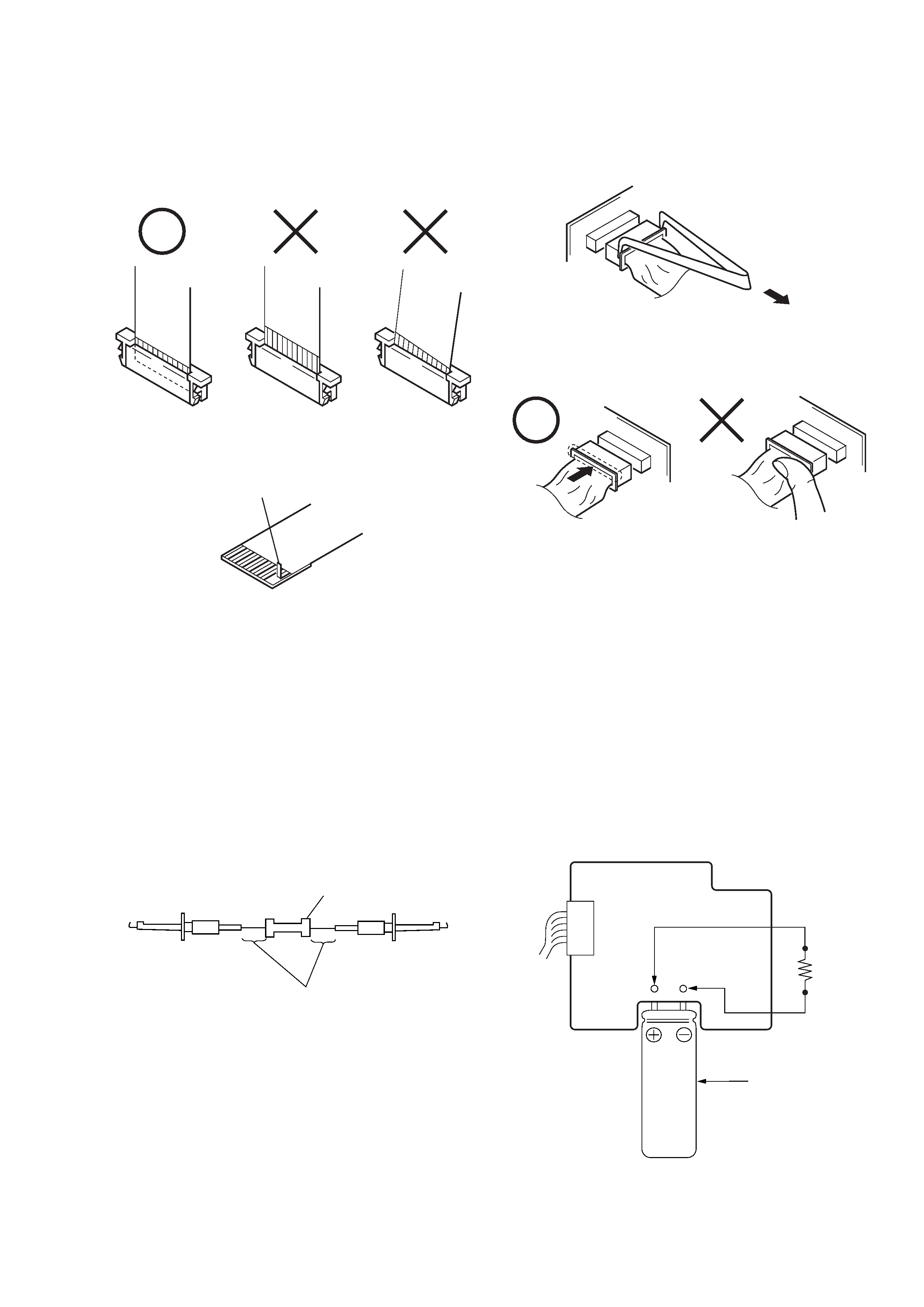
Preparing the Short Jig
To preparing the short jig. a small clip is attached to each end of a
resistor of 1 k
/1 W (1-215-869-11)
Wrap insulating tape fully around the leads of the resistor to prevent
electrical shock.
1 k
/1 W
Wrap insulating tape.
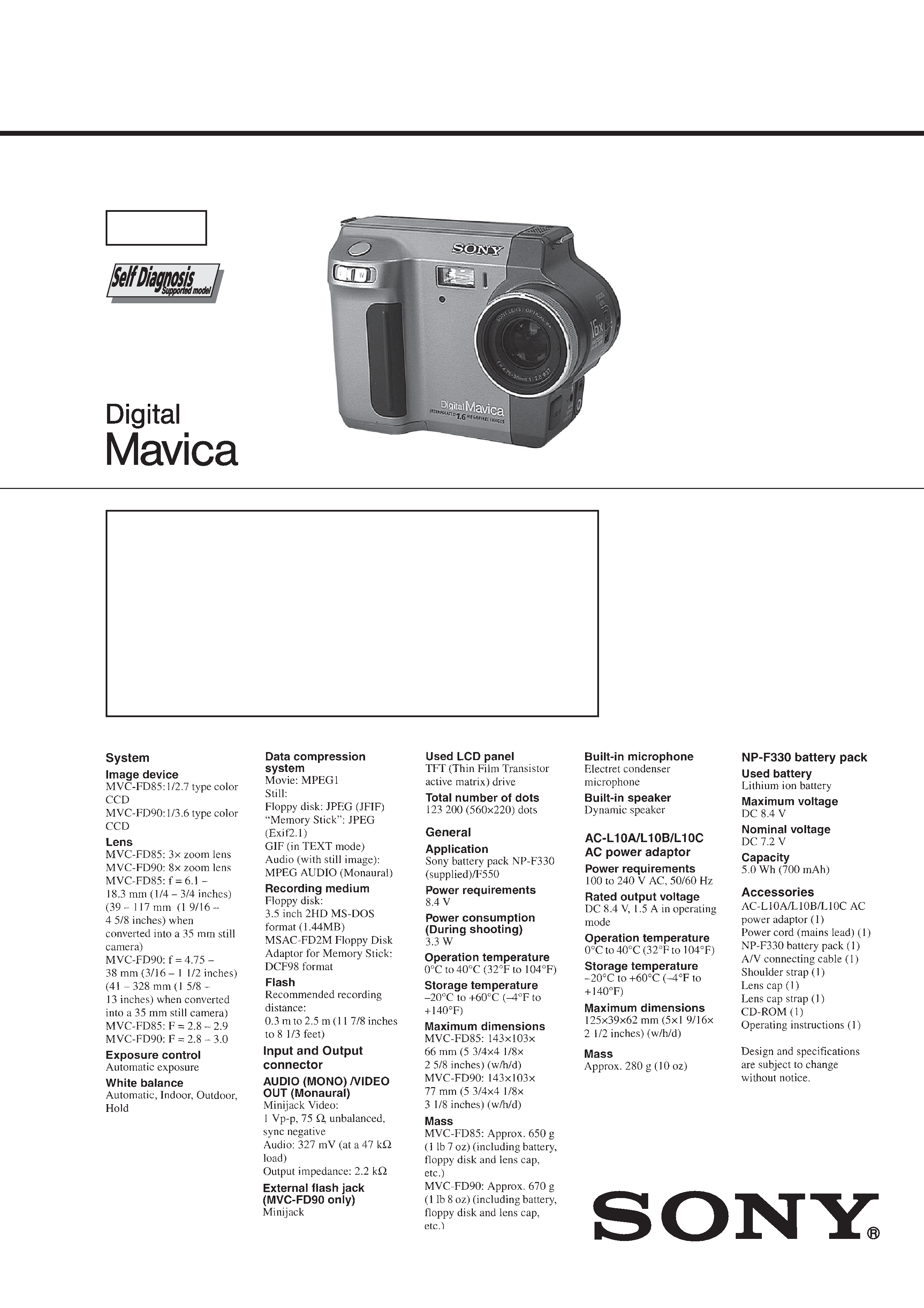
Make sure that the flat cable and flexible board are not cracked of
bent at the terminal.
Do not insert the cable insufficiently nor crookedly.
Cut and remove the part of gilt
which comes off at the point.
(Take care that there are
some pieces of gilt left inside)
When remove a connector, don't pull at wire of connector.
Be in danger of the snapping of a wire.
When installing a connector, don't press down at wire of connector.
Be in danger of the snapping of a wire.
Discharging the Capacitor
Short circuits between the positive and the negative terminals of
charged capacitor with the short jig about 10 seconds.
Capacitor
Short jig