SERVICE MANUAL
Ver 1.0 2001. 01
DIGITAL STILL CAMERA
MVC-FD75
US Model
Canadian Model
AEP Model
UK Model
E Model
Hong Kong Model
Australian Model
Brazilian Model
SPECIFICATIONS

2
1. Check the area of your repair for unsoldered or poorly-sol-
dered connections. Check the entire board surface for solder
splashes and bridges.
2. Check the interboard wiring to ensure that no wires are
"pinched" or contact high-wattage resistors.
3. Look for unauthorized replacement parts, particularly transis-
tors, that were installed during a previous repair. Point them
out to the customer and recommend their replacement.
SAFETY CHECK-OUT
After correcting the original service problem, perform the following
safety checks before releasing the set to the customer.
4. Look for parts which, though functioning, show obvious signs
of deterioration. Point them out to the customer and recom-
mend their replacement.
5. Check the B+ voltage to see it is at the values specified.
6. Flexible Circuit Board Repairing
·
Keep the temperature of the soldering iron around 270 °C
during repairing.
·
Do not touch the soldering iron on the same conductor of
the circuit board (within 3 times).
·
Be careful not to apply force on the conductor when sol-
dering or unsoldering.
ATTENTION AU COMPOSANT AYANT RAPPORT
À LA SÉCURITÉ!
LES COMPOSANTS IDENTIFIÉS PAR UNE MARQUE 0
SUR LES DIAGRAMMES SCHÉMATIQUES ET LA LISTE
DES PIÈCES SONT CRITIQUES POUR LA SÉCURITÉ
DE FONCTIONNEMENT. NE REMPLACER CES COM-
POSANTS QUE PAR DES PIÈCES SONY DONT LES
NUMÉROS SONT DONNÉS DANS CE MANUEL OU
DANS LES SUPPLÉMENTS PUBLIÉS PAR SONY.
SAFETY-RELATED COMPONENT WARNING!!
COMPONENTS IDENTIFIED BY MARK 0 OR DOTTED
LINE WITH MARK 0 ON THE SCHEMATIC DIAGRAMS
AND IN THE PARTS LIST ARE CRITICAL TO SAFE
OPERATION. REPLACE THESE COMPONENTS WITH
SONY PARTS WHOSE PART NUMBERS APPEAR AS
SHOWN IN THIS MANUAL OR IN SUPPLEMENTS PUB-
LISHED BY SONY.
· Floppy disk that can be used by the MVC-FD75
· Size :
3.5-inch
· Type :
2 HD
· Capacity :
1.44 MB
· Format :
MS-DOS format
(512 bytes
× 18 sector)
(FD can be formatted by the MVC-FD75)

3
SERVICE NOTE
Note for Repair ........................................................................ 5
Discharging of the FLASH Unit's Charging Capacitor ............ 5
How to Connect the Extension Cable ..................................... 6
Description on Self-diagnosis Display .................................... 7
Power Supplying Method ........................................................ 7
1.
GENERAL
Be Sure to Read Before Using Your Camera ......................... 1-1
Before Using Your Camera ..................................................... 1-2
Parts Identification ................................................................... 1-2
Preparation .............................................................................. 1-3
Recording and Playing Back Images ...................................... 1-4
Changing the Mode Settings ................................................... 1-5
Using Various Functions for Recording .................................. 1-8
Changing the Lithium Battery in the Camera ......................... 1-8
Precautions .............................................................................. 1-8
Troubleshooting ....................................................................... 1-9
Self-diagnosis Display ............................................................. 1-10
2.
DISASSEMBLY
2-1.
Cabinet (Front) Block Assembly .................................. 2-1
2-2.
FC-86 Board .................................................................. 2-1
2-3.
Lens Block Assembly .................................................... 2-2
2-4.
Motor Units .................................................................... 2-2
2-5.
FDD Block Assembly ..................................................... 2-3
2-6.
PK-59 Board, LCD Module ........................................... 2-3
2-7.
Circuit Boards Location ................................................. 2-4
3.
BLOCK DIAGRAMS
3-1.
Overall Block Diagram .................................................. 3-1
3-2.
Camera Block Diagram ................................................. 3-3
3-3.
Lens Motor Drive Block Diagram .................................. 3-5
3-4.
FDD Interface Block Diagram ....................................... 3-7
3-5.
Mode Control Block Diagram ........................................ 3-9
3-6.
LCD Block Diagram ....................................................... 3-11
3-7.
Power Block Diagram .................................................... 3-13
4.
PRINTED WIRING BOARDS AND
SCHEMATIC DIAGRAMS
4-1.
Frame Schematic Diagrams ......................................... 4-3
Frame Schematic Diagram (1/2) ................................... 4-3
Frame Schematic Diagram (2/2) ................................... 4-5
4-2.
Printed Wiring Boards and Schematic Diagrams ......... 4-7
CD-338 Printed Wiring Board and
Schematic Diagram ....................................................... 4-7
FC-86 Printed Wiring Board .......................................... 4-9
FC-86 (CAMERA) Schematic Diagram ......................... 4-11
FC-86 (DRAM CONTROL) Schematic Diagram ......... 4-13
FC-86 (D/A CONVERTER) Schematic Diagram ......... 4-15
FC-86 (CAMERA SERVO/EVR DECODER)
Schematic Diagram ....................................................... 4-17
FC-86 (FDD CONTROL (1/2)) Schematic Diagram ..... 4-19
FC-86 (FDD CONTROL (2/2)) Schematic Diagram ..... 4-21
FC-86 (MODE/SYSTEM CONTROL)
Schematic Diagram ....................................................... 4-23
FC-86 (DC/DC CONVERTER) Schematic Diagram ..... 4-25
PK-59 Printed Wiring Board .......................................... 4-27
PK-59 (FDD INTERFACE) Schematic Diagram .......... 4-31
PK-59 (LCD DRIVE) Schematic Diagram .................... 4-33
PK-59 (LCD TIMING GENERATOR)
Schematic Diagram ....................................................... 4-35
PK-59 (MODE KEY SWITCH) Schematic Diagram .... 4-37
PK-59 (BACK LIGHT) Schematic Diagram ................. 4-39
TABLE OF CONTENTS
Section
Title
Page
Section
Title
Page
RL-58 Printed Wiring Board and
Schematic Diagram ....................................................... 4-41
4-3.
Waveforms .................................................................... 4-43
4-4.
Parts Location ............................................................... 4-45
5.
ADJUSTMENTS
1.
Before Starting Adjustment ........................................... 5-1
1-1.
Adjusting Items when Replacing
Main Parts and Boards .................................................. 5-2
5-1.
Camera Section Adjustments ........................................ 5-3
1-1.
Preparations Before Adjustment ................................... 5-3
1-1-1. List of Service Tools ................................................. 5-3
1-1-2. Preparations ............................................................. 5-4
1-1-3. Discharging of the Flashlight Power Supply ............ 5-4
1-1-4. Precautions .............................................................. 5-6
1. Setting the Switch .................................................... 5-6
2. Order of Adjustments ............................................... 5-6
3. Subjects .................................................................... 5-6
1-2.
Initialization of E and F Page Data ............................... 5-7
1. Initializing E and F Page Data ................................. 5-7
2. Modification of E and F Page Data .......................... 5-7
3. E Page Table ............................................................ 5-7
4. F Page Table ............................................................ 5-8
1-3.
Camera System Adjustments ........................................ 5-9
1.
HALL Adjustment ........................................................... 5-9
2.
Flange Back Adjustment
(Using the Minipattern Box) .......................................... 5-10
3.
Flange Back Adjustment
(Using the Flange Back Adjustment Chart) .................. 5-11
4.
Flange Back Check ....................................................... 5-12
5.
Picture Frame Setting ................................................... 5-12
6.
Light Level Adjustment .................................................. 5-13
7.
Auto White Balance Standard Data Input ..................... 5-13
8.
Auto White Balance Adjustment ................................... 5-14
9.
White Balance Check .................................................... 5-14
10. Color Reproduction Adjustment .................................... 5-15
1-4.
LCD System Adjustments ............................................. 5-16
1.
LCD Initial Data Input .................................................... 5-17
2.
VCO Adjustment (PK-59 Board) ................................... 5-17
3.
D Range Adjustment (PK-59 Board) ............................. 5-18
4.
Bright Adjustment (PK-59 Board) .................................. 5-18
5.
Contrast Adjustment (PK-59 Board) ............................. 5-19
6.
V-COM Level Adjustment (PK-59 Board) ..................... 5-19
7.
V-COM Adjustment (PK-59 Board) ............................... 5-20
8.
White Balance Adjustment (PK-59 Board) ................... 5-20
1-5.
System Control System Adjustments ........................... 5-21
1.
Battery Down Adjustment (FC-86 Board) ..................... 5-21
2.
Alignment Check (FDD Unit) ......................................... 5-21
5-2.
Service Mode ................................................................ 5-22
2-1.
Adjusting Remote Commander ..................................... 5-22
1.
Used the Adjusting Remote Commander ..................... 5-22
2.
Precautions upon Using
the Adjusting Remote Commander ............................... 5-22
2-2.
Data Process ................................................................. 5-23
2-3.
Service Mode ................................................................ 5-24
1.
Setting the Test Mode ................................................... 5-24
2.
Bit Value Discrimination ................................................ 5-24
3.
Switch Check (1) ........................................................... 5-24
4.
Switch Check (2) ........................................................... 5-25
5.
LED Check .................................................................... 5-25
6.
Self Diagnosis Code ...................................................... 5-25

4
Section
Title
Page
* The color reproduction frame is shown on page 125.
6.
REPAIR PARTS LIST
6-1.
Exploded Views ............................................................. 6-1
6-1-1. Cabinet (Front) Section ........................................... 6-1
6-1-2. Cabinet (Rear) Section ........................................... 6-2
6-1-3. Lens Block Section ................................................... 6-3
6-2.
Electrical Parts List ........................................................ 6-4
5
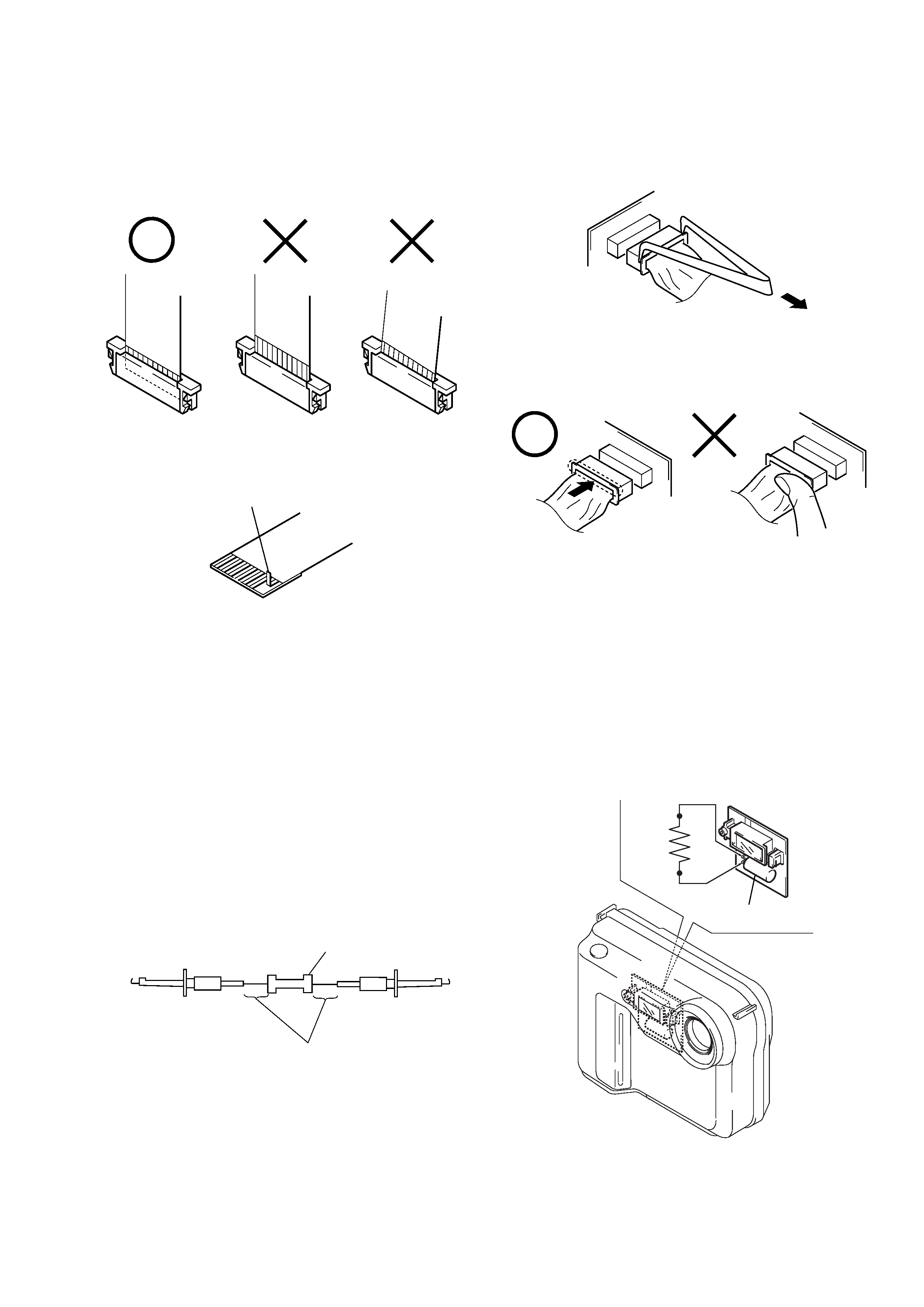
[Discharging of the FLASH unit's charging capacitor]
The charging capacitor of the FLASH unit is charged up to the
maximum 300 V potential.
There is a danger of electric shock by this high voltage when the
battery is handled by hand. The electric shock is caused by the
charged voltage which is kept without discharging when the main
power of the MVC-FD75 is simply turned off. Therefore, the re-
maining voltage must be discharged as described below.
Preparing the Short Jig
To preparing the short jig. a small clip is attached to each end of a
resistor of 1 k
/1 W (1-215-869-11).
Wrap insulating tape fully around the leads of the resistor to pre-
vent electrical shock.
1 k
/1 W
Wrap insulating tape.
Discharging the Capacitor
Short-circuit between the positive and the negative terminals of
charged capacitor with the short jig about 10 seconds.
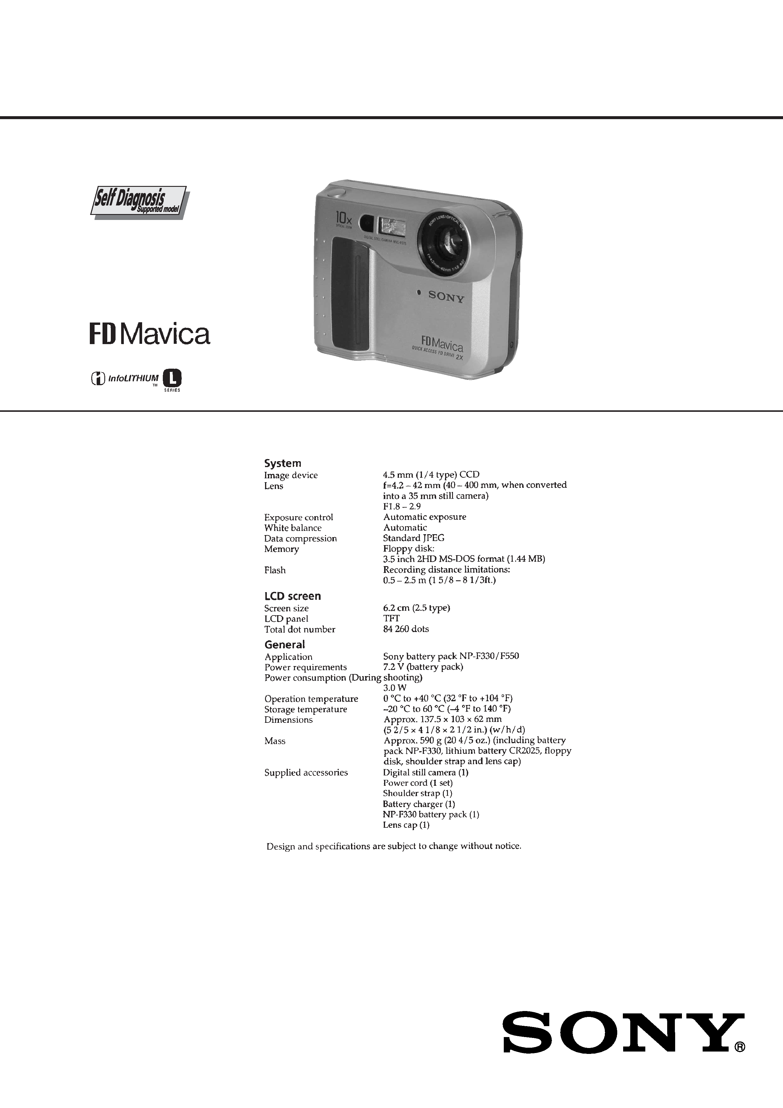
SERVICE NOTE
· NOTE FOR REPAIR
Make sure that the flat cable and flexible board are not cracked of
bent at the terminal.
Do not insert the cable insufficiently nor crookedly.
When remove a connector, don't pull at wire of connector.
It is possible that a wire is snapped.
Cut and remove the part of gilt
which comes off at the point.
(Be careful or some pieces of
gilt may be left inside)
When installing a connector, don't press down at wire of connector.
It is possible that a wire is snapped.
Capacitor
R: 1 k
/1 W
(Part code:
1-215-869-11)