MICROFILM
SERVICE MANUAL
DIGITAL STILL CAMERA
US Model
Canadian Model
AEP Model
UK Model
E Model
Australian Model
Hong Kong Model
Tourist Model
SPECIFICATIONS
MVC-FD71
Ver 1.3 2000. 09
With SUPPLEMENT-1
(9-974-076-81)

2
SAFETY-RELATED COMPONENT WARNING!!
COMPONENTS IDENTIFIED BY MARK
! OR DOTTED LINE WITH
MARK
! ON THE SCHEMATIC DIAGRAMS AND IN THE PARTS
LIST ARE CRITICAL TO SAFE OPERATION. REPLACE THESE
COMPONENTS WITH SONY PARTS WHOSE PART NUMBERS
APPEAR AS SHOWN IN THIS MANUAL OR IN SUPPLEMENTS
PUB-LISHED BY SONY.
ATTENTION AU COMPOSANT AYANT RAPPORT
À LA SÉCURITÉ!
LES COMPOSANTS IDENTIFÉS PAR UNE MARQUE
! SUR LES
DIAGRAMMES SCHÉMATIQUES ET LA LISTE DES PIÈCES
SONT CRITIQUES POUR LA SÉCURITÉ DE FONCTIONNEMENT.
NE REMPLACER CES COMPOSANTS QUE PAR DES PIÈSES
SONY DONT LES NUMÉROS SONT DONNÉS DANS CE MANUEL
OU DANS LES SUPPÉMENTS PUBLIÉS PAR SONY.
1.
Check the area of your repair for unsoldered or poorly-sol-
dered connections. Check the entire board surface for solder
splashes and bridges.
2.
Check the interboard wiring to ensure that no wires are
"pinched" or contact high-wattage resistors.
3.
Look for unauthorized replacement parts, par-ticularly tran-
sistors, that were installed during a previous repair. Point
them out to the customer and recommend their replacement.
4.
Look for parts which, through functioning, show obvious
signs of deterioration. Point them out to the customer and
recommend their replace-ment.
5.
Check the B+ voltage to see it is at the values specified.
6.
Flexible Circuit Board Repairing
· Keep the temperature of the soldering iron around 270°C dur-
ing repairing.
· Do not touch the soldering iron on the same conductor of the
circuit board (within 3 times).
· Be careful not to apply force on the conductor when solder-
ing or unsoldering.
SAFETY CHECK-OUT
After correcting the original service problem, perform the following
safety checks before releasing the set to the customer.
· Floppy disk that can be used by the MVC-FD71
· Size :
3.5-inch
· Type :
2 HD
· Capacity :
1.44 MB
· Format :
MS-DOS format
(512 bytes
× 18 sector)
(FD can be formatted by the MVC-FD71)

3
TABLE OF CONTENTS
SERVICE NOTE
Discharging of the FLASH units charging capacitor ............... 4
LCD type judging method ........................................................ 4
How to connect the extension cable ....................................... 5
Description on self diagnosis display ...................................... 6
Power supplying method ......................................................... 6
1.
GENERAL
Be sure to read before using your camera ............................. 1-1
Before using your camera ....................................................... 1-1
Parts identification ................................................................... 1-1
Preparation .............................................................................. 1-2
Recording and playing back images ....................................... 1-3
Changing the mode settings ................................................... 1-5
Using various function for recording ....................................... 1-7
Changing the lithium battery in the camera ............................ 1-7
Precautions .............................................................................. 1-8
Trouble shooting ...................................................................... 1-8
Self diagnosis display .............................................................. 1-9
2.
DISASSEMBLY
2-1.
CABINET (FRONT) BLOCK ASSEMBLY ..................... 2-1
2-2.
FC-66 BOARD ............................................................... 2-1
2-3.
LENS BLOCK ASSEMBLY ............................................ 2-1
2-4.
MOTOR UNITS .............................................................. 2-1
2-5.
FDD BLOCK ASSEMBLY .............................................. 2-2
2-6.
PK-43 BOARD, LIQUID CRYSTAL
INDICATOR MODULE ................................................... 2-2
2-7.
CIRCUIT BOARDS LOCATION .................................... 2-2
3.
BLOCK DIAGRAMS
3-1.
OVER ALL BLOCK DIAGRAM ...................................... 3-1
3-2.
CAMERA BLOCK DIAGRAM ........................................ 3-5
3-3.
FDD INTERFACE BLOCK DIAGRAM ........................... 3-7
3-4.
MODE CONTROL BLOCK DIAGRAM .......................... 3-11
3-5.
LCD BLOCK DIAGRAM ................................................ 3-13
3-6.
POWER BLOCK DIAGRAM .......................................... 3-16
4.
PRINTED WIRING BOARDS AND
SCHEMATIC DIAGRAMS
4-1.
FRAME SCHEMATIC DIAGRAM .................................. 4-1
4-2.
PRINTED WIRING BOARDS AND
SCHEMATIC DIAGRAMS ............................................. 4-4
· CD-196 (CCD IMAGER)
PRINTED WIRING BOARD AND
SCHEMATIC DIAGRAM ........................................... 4-5
· RL-50 (RELEASE SWITCH)/FC-66 (MAIN)
PRINTED WIRING BOARDS ................................... 4-7
· FC-66 (CAMERA)
SCHEMATIC DIAGRAM ........................................... 4-13
· FC-66 (DRAM CONTROL)
SCHEMATIC DIAGRAM ........................................... 4-15
· FC-66 (D/A CONVERTER)
SCHEMATIC DIAGRAM ........................................... 4-18
· FC-66 (CAMERA SERVO)
SCHEMATIC DIAGRAM ........................................... 4-21
· FC-66 (FDD CONTROL)
SCHEMATIC DIAGRAM ........................................... 4-26
· FC-66 (MODE CONTROL), (EVR DECODER)
SCHEMATIC DIAGRAM ........................................... 4-29
· FC-66 (DC/DC CONVERTER)
RL-50 (RELEASE SWITCH)
SCHEMATIC DIAGRAM ........................................... 4-34
· PK-43 (LCD PANEL, MODE KEY)
PRINTED WIRING BOARD ..................................... 4-37
· PK-43 (FDD INTERFACE)
SCHEMATIC DIAGRAM ........................................... 4-42
· PK-43 (RGB CECODER)
SCHEMATIC DIAGRAM ........................................... 4-45
· PK-43 (LCD TIMING GENERATOR)
SCHEMATIC DIAGRAM ........................................... 4-49
· PK-43 (MODE KEY SWITCH)
SCHEMATIC DIAGRAM ........................................... 4-51
· PK-43 (BACK LIGHT)
SCHEMATIC DIAGRAM ........................................... 4-53
5.
ADJUSTMENTS
5-1.
CAMERA SECTION ADJUSTMENT ............................ 5-1
1-1.
PREPARATIONS BEFORE ADJUSTMENT ................. 5-1
1-1-1. List of service tools .................................................. 5-1
1-1-2. Precautions .............................................................. 5-2
1.
Switch settings ......................................................... 5-2
2.
Adjustment sequence ............................................... 5-2
3.
Subject ...................................................................... 5-2
1-1-3. Preparations ............................................................. 5-3
1-1-4. Discharge of flashlight power supply ....................... 5-4
1-1-5. Adjustment remote commander ............................... 5-4
1.
Using the adjustment remote commander .............. 5-4
2.
Precautions when using the adjustment
remote commander .................................................. 5-5
1-1-6. Data processing ....................................................... 5-6
1-2.
INITIALIZATION OF E AND F PAGE DATA ............. 5-7
1.
Intialization of E and F page data ............................ 5-7
2.
Modification of F, E page data ................................. 5-7
3.
F page table ............................................................. 5-7
4.
E page table ............................................................. 5-10
1-3.
CAMERA SYSTEM ADJUSTMENT ......................... 5-12
1.
Adjustment points when major parts
have been replaced .................................................. 5-12
2.
Power supply voltage check ..................................... 5-12
3.
HALL adjustment ...................................................... 5-12
4.
Flange back adjustment ........................................... 5-13
5.
Flange back check ................................................... 5-14
6.
Picture frame setting ................................................ 5-14
7.
Light level adjustment .............................................. 5-15
8.
Auto white balance reference data input ................. 5-15
9.
Auto white balance adjustment ................................ 5-16
10.
White balance check ................................................ 5-16
11.
Hue gain adjustment ................................................ 5-17
1-4.
LCD SYSTEM ADJUSTMENT ...................................... 5-18
1.
Power supply voltage check ..................................... 5-19
2.
EVR initial data input ................................................ 5-19
3.
VCO adjustment ....................................................... 5-19
4.
D RANGE adjustment .............................................. 5-20
5.
BRIGHT adjustment ................................................. 5-20
6.
CONTRAST adjustment ........................................... 5-21
7.
V-COM level adjustment .......................................... 5-21
8.
V-COM adjustment ................................................... 5-22
9.
White balance adjustment ...................................... 5-22
1-5.
SYSTEM CONTROL SYSTEM ADJUSTMENT ........... 5-23
1.
Battery down adjustment ......................................... 5-23
2.
Battery down check .................................................. 5-23
6.
REPAIR PARTS LIST
6-1.
EXPLODED VIEWS ...................................................... 6-1
6-1-1.
CABINET (FRONT) SECTION ................................. 6-1
6-1-2.
CABINET (REAR) SECTION ................................... 6-2
6-1-3.
LENS BLOCK ASSY SECTION ............................... 6-3
6-2.
ELECTRICAL PARTS LIST ........................................... 6-4
* The color reproduction frame is shown after the
page of ELECTRICAL PARTS LIST.
4
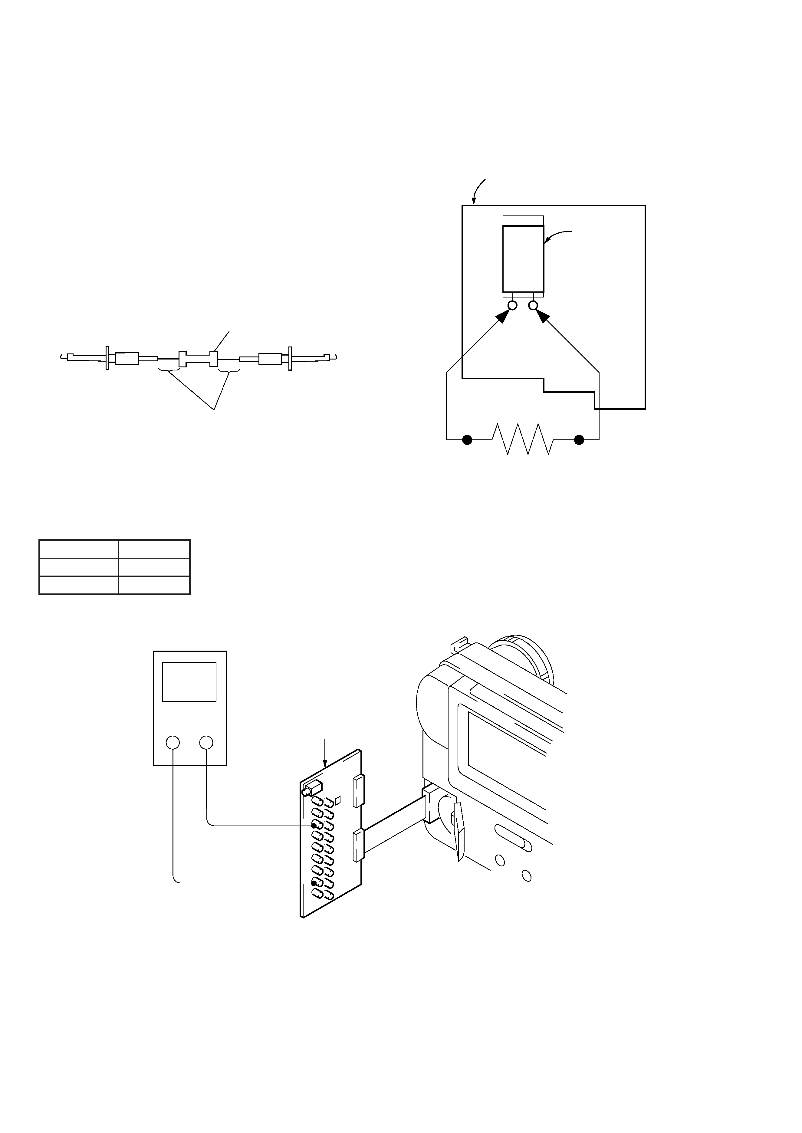
[Discharging of the FLASH unit's charging capacitor]
The charging capacitor of the FLASH unit is charged up to the
maximum 300 V potential.
There is a danger of electric shock by this high voltage when the
battery is handled by hand. The electric shock is caused by the
charged voltage which is kept without discharging when the main
power of the MVC-FD71 is simply turned off. Therefore, the re-
maining voltage must be discharged as described below.
Preparing the Short Jig
To preparing the short jig. a small clip is attached to each end of a
resistor of 1k
/1W (1-215-869-11)
Wrap insulating tape fully around the leads of the resistor to pre-
vent electrical shock.
1k
/1W
Wrap insulating tape.
Discharging the Capacitor
Short-circuit between the positive and the negative terminals of
charged capacitor with the short jig about 10 seconds.
SERVICE NOTE
[LCD type judging method]
The LCD type can be judged by measuring resistance between 4
pin and !¢ pin of CPC-9 jig.
Resistance
LCD Type
10 k
SHARP
0
CASIO
Flash unit
Charge
capacitor
Short jig
+
Digital voltmeter
!¢ pin
4 pin
CPC-9 jig
(J-6082-393-B)
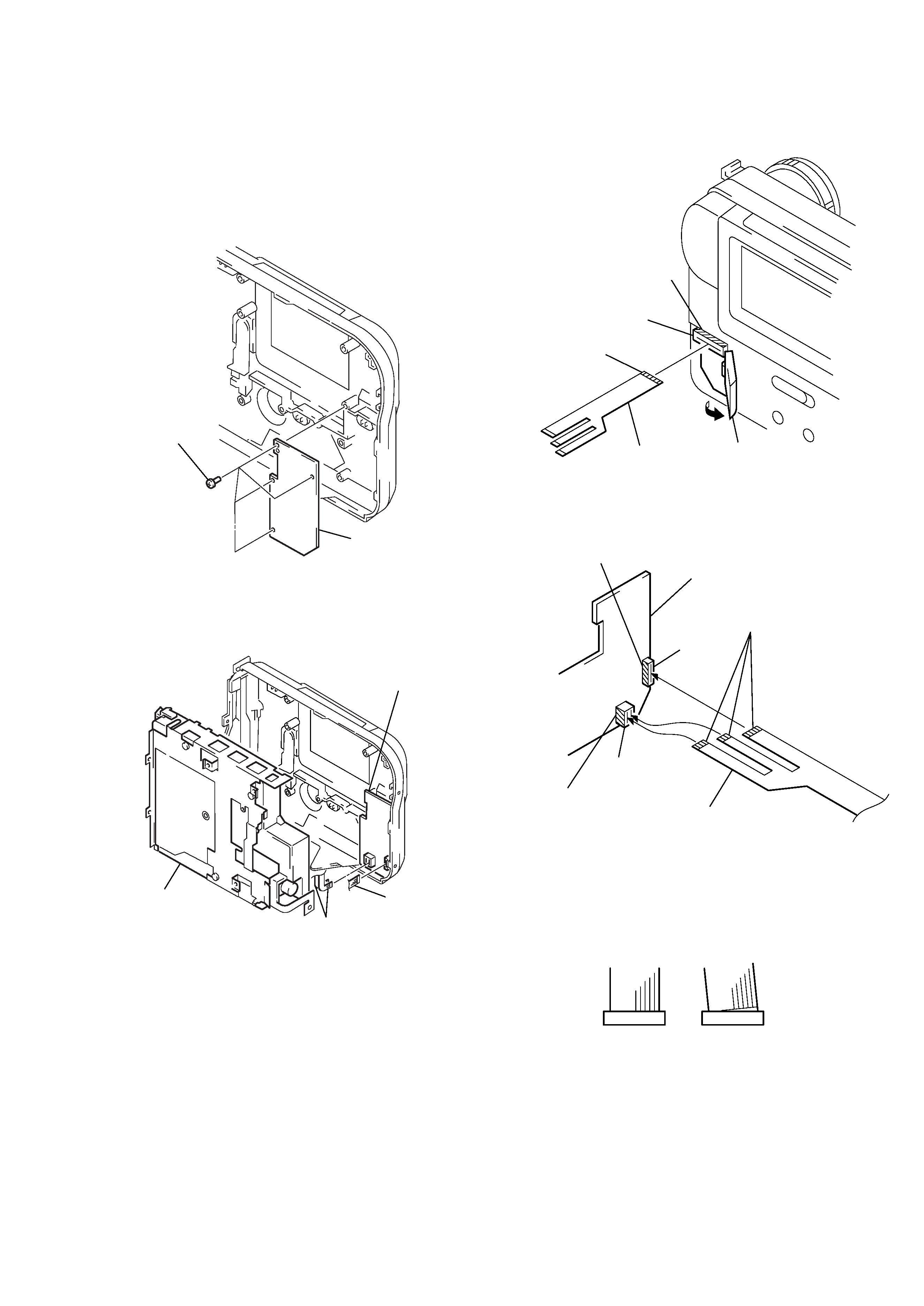
5
Extension cable
(J-6082-427-A)
Four screws
Flexible board
(CN012)
Flexible board
(CN011)
Floppy disk drive
Extension cable
(J-6082-427-A)
Contact side
CN013
Contact side
Lithium lid
Extension cable
(J-6082-427-A)
CN602
Contact side
CN601
Contact side
PK-43 board
Extension cable
(J-6082-427-A)
For both two cables,
the contact points are
on this side.
Good
NG
[How to connect the extension cable]
1) Remove the PK-43 board and the liquid crystal indication
module. (See page 2-2E.)
Note : Be careful not to breake the flexible board of the floppy disk drive.
2) Install the Extension cable (J-6082-427-A) on the rear cabi-
net. (See Fig. 1.)
3) Install the floppy disk drive. (See Fig. 2.)
4) Open the lithium lid. (See Fig. 3.)
5) Mount the flexible board on CN013. (See Fig. 3.)
6) Install the PK-43 board. (See Fig. 4.)
Note : The floppy disk drive and PK-43 board could be destroyed unless
the flexible board is connected normally to the connector.
(See Fig. 5.)
Fig. 3
Fig. 2
Fig. 4
Fig. 5
Fig. 1