MVC-FD5/FD7
US Model
Canadian Model
AEP Model
UK Model
E Model
SERVICE MANUAL
DIGITAL STILL CAMERA
MICROFILM
SPECIFICATIONS
MVC-FD5
MVC-FD7

-- 2 --
SAFETY-RELATED COMPONENT WARNING!!
COMPONENTS IDENTIFIED BY MARK
!OR DOTTED LINE WITH
MARK
! ON THE SCHEMATIC DIAGRAMS AND IN THE PARTS
LIST ARE CRITICAL TO SAFE OPERATION. REPLACE THESE
COMPONENTS WITH SONY PARTS WHOSE PART NUMBERS
APPEAR AS SHOWN IN THIS MANUAL OR IN SUPPLEMENTS
PUB-LISHED BY SONY.
ATTENTION AU COMPOSANT AYANT RAPPORT
À LA SÉCURITÉ!
LES COMPOSANTS IDENTIFÉS PAR UNE MARQUE
! SUR LES
DIAGRAMMES SCHÉMATIQUES ET LA LISTE DES PIÈCES SONT
CRITIQUES POUR LA SÉCURITÉ DE FONCTIONNEMENT. NE
REMPLACER CES COMPOSANTS QUE PAR DES PIÈSES SONY
DONT LES NUMÉROS SONT DONNÉS DANS CE MANUEL OU
DANS LES SUPPÉMENTS PUBLIÉS PAR SONY.
1.
Check the area of your repair for unsoldered or poorly-soldered
connections. Check the entire board surface for solder splashes
and bridges.
2.
Check the interboard wiring to ensure that no wires are
"pinched" or contact high-wattage resistors.
3.
Look for unauthorized replacement parts, par-ticularly
transistors, that were installed during a previous repair. Point
them out to the customer and recommend their replacement.
4.
Look for parts which, through functioning, show obvious signs
of deterioration. Point them out to the customer and
recommend their replace-ment.
5.
Check the B+ voltage to see it is at the values specified.
6.
Flexible Circuit Board Repairing
· Keep the temperature of the soldering iron around 270°C
during repairing.
· Do not touch the soldering iron on the same conductor of the
circuit board (within 3 times).
· Be careful not to apply force on the conductor when soldering
or unsoldering.
SAFETY CHECK-OUT
After correcting the original service problem, perform the following
safety checks before releasing the set to the customer.
· Table for difference of function
Model number
Macro recording
Zoom
Manual focusing
Picture effect
Program AE
MVC-FD5
Macro switch
--
--
--
--
MVC-FD7
Auto
q
q
q
q
· Floppy disk that can be used by the MVC-FD5/FD7.
· Size:
3.5-inch
· Type:
2 HD
· Capacity: 1.44 MB
· Format: MS-DOS format
(512 bytes
× 18 sectors)
(FD can be formatted by the MVC-FD5/FD7.)

-- 3 --
TABLE OF CONTENTS
SERVICE NOTE ····································································· 5
1.
GENERAL
Be sure to read before using your camera ······························ 1-1
Before using your camera ······················································· 1-1
Preparation ·············································································· 1-1
Step 1: Charging the battery pack ·········································· 1-2
Step 2: Installing the battery pack ·········································· 1-2
Step 3: Setting the date and time ············································ 1-2
Recording images ··································································· 1-3
Watching images on the LCD screen ····································· 1-5
Viewing images using a personal computer ··························· 1-7
Using various functions for recording (MVC-FD7 only) ······· 1-8
Changing the Lithium battery in the camera ·························· 1-9
Precautions ············································································· 1-9
Troubleshooting ······································································ 1-9
Self-diagnosis diaplay ···························································· 1-10
Parts identification ·································································· 1-10
2.
DISASSEMBLY
2-1.
REMOVAL OF CABINET (FRONT) ASSEMBLY ···· 2-1
2-2.
REMOVAL OF FLASH UNIT ····································· 2-1
2-3.
REMOVAL OF FU-131 BOARD AND
RL-49 BOARD ····························································· 2-1
2-4.
REMOVAL OF FC-63 BOARD AND FDD ················ 2-2
2-5.
REMOVAL OF FC-63 BOARD AND
LENS ASSEMBLY ······················································ 2-2
2-6.
REMOVAL OF PK-42 BOARD AND
CRYATAL INDICATION MODULE ·························· 2-3
2-7.
REMOVAL OF CD-177 BOARD,
MF-308 BOARD AND ZOOM LENS
(MVC-FD7 MODEL) ··················································· 2-3
2-8.
CIRCUIT BOARDS LOCATION ································ 2-3
3.
BLOCK DIAGRAMS
3-1.
OVERALL BLOCK DIAGRAM ································· 3-1
3-2.
CAMERA BLOCK DIAGRAM ·································· 3-5
3-3.
FDD INTERFACE BLOCK DIAGRAM ····················· 3-7
3-4.
MODE CONTROL BLOCK DIAGRAM ···················· 3-9
3-5.
LCD DRIVE BLOCK DIAGRAM ······························ 3-11
3-6.
POWER SUPPLY BLOCK DIAGRAM ······················ 3-13
4.
PRINTED WIRING BOARDS AND
SCHEMATIC DIAGRAMS
4-1.
FRAME SCHEMATIC DIAGRAM ····························· 4-1
4-2.
PRINTED WIRING BOARDS AND
SCHEMATIC DIAGRAMS ········································· 4-4
· CD-176 (CCD IMAGER)
PRINTED WIRING BOARD AND
SCHEMATIC DIAGRAM
(MVC-FD5 MODEL) ································· 4-5
· CD-177 (CCD IMAGER)
PRINTED WIRING BOARD AND
SCHEMATIC DIAGRAM
(MVC-FD7 MODEL) ································· 4-7
· MF-308 (ZOOM DIAL)
PRINTED WIRING BOARD AND
SCHEMATIC DIAGRAM
(MVC-FD7 MODEL) ································· 4-9
· FC-63 (MAIN) PRINTED WIRING BOARD ········ 4-12
· FC-63 (CAMERA (1))
SCHEMATIC DIAGRAM ·························· 4-15
· FC-63 (CAMERA (2))
SCHEMATIC DIAGRAM ·························· 4-18
· FC-63 (CAMERA SERVO)
SCHEMATIC DIAGRAM ·························· 4-21
· FC-63 (EVR DECODER)
SCHEMATIC DIAGRAM ·························· 4-24
· FC-63 (MODE/SYSTEM CONTROL)
SCHEMATIC DIAGRAM ·························· 4-26
· FC-63 (DRAM CONTROL)
SCHEMATIC DIAGRAM ·························· 4-29
· FC-63 (FDD INTERFACE)
SCHEMATIC DIAGRAM ·························· 4-33
· FC-63 (RGB DECODER)
SCHEMATIC DIAGRAM ·························· 4-37
· FC-63 (DC/DC CONVERTER)
SCHEMATIC DIAGRAM ·························· 4-40
· FU-131 (FUSE) PRINTED WIRING BOARD AND
SCHEMATIC DIAGRAM ·························· 4-43
· RL-49 (RELEASE SWITCH)
PRINTED WIRING BOARD AND
SCHEMATIC DIAGRAM ·························· 4-45
· PK-42 (LCD PANEL, MODE KEY)
PRINTED WIRING BOARD ····················· 4-48
· PK-42 (RGB CORRECTION)
SCHEMATIC DIAGRAM ·························· 4-51
· PK-42 (LCD TIMING GENERATOR)
SCHEMATIC DIAGRAM ·························· 4-55
· PK-42 (BACK LIGHT)
SCHEMATIC DIAGRAM ·························· 4-57
· PK-42 (MODE KEY SWITCH)
SCHEMATIC DIAGRAM ·························· 4-59
5.
REPAIR PARTS LIST
5-1.
EXPLODED VIEWS ··················································· 5-1
5-1-1. CABINET (FRONT) SECTION ·································· 5-1
5-1-2. CABINET (REAR) SECTION ···································· 5-2
5-1-3. ZOOM LENS (VCL-4210VB) SECTION
(MVC-FD7 MODEL) ··················································· 5-3
5-1-4. LENS BLOCK SECTION (MVC-FD7 MODEL) ······· 5-4
5-2.
ELECTRICAL PARTS LIST ······································· 5-5
6.
ADJUSTMENTS
6-1.
CAMERA SECTION ADJUSTMENT ························ 6-1
1-1.
PREPARATIONS BEFORE ADJUSTMENT ·············· 6-1
1-1-1. List of service tools ······················································ 6-1
1-1-2. Precautions ··································································· 6-2
1.
Switch settings ······························································ 6-2
2.
Adjustment sequence ···················································· 6-2
3.
Subject ·········································································· 6-2
1-1-3. Preparations ·································································· 6-3
1-1-4. Discharge of flashlight power supply ··························· 6-4
1-1-5. Adjustment remote commander
(RM-95 upgraded) ························································ 6-4
1.
Using the adjustment remote commander ···················· 6-4
2.
Precautions when using
the adjustment remote commander ······························· 6-5
1-1-6. Page F Address List ······················································ 6-6
1-1-7. Page E Address List ······················································ 6-9
1-2.
CAMERA SYSTEM ADJUSTMENTS ······················· 6-10
1.
Adjustment points when
major parts have been replaced ···································· 6-10
2.
Power supply voltage check (FC-63 board) ················· 6-10
3.
Preparation for adjustment ··········································· 6-10
4.
Initialization of page F data ·········································· 6-11
5.
Modification of Page F Data ········································ 6-11
6.
Modification of Page E Data ········································ 6-11

-- 4 --
7.
Data Processing ···························································· 6-12
8.
HALL adjustment ························································· 6-14
9.
Flange back adjustment (MVC-FD7 model) ················ 6-15
10.
Flange back check (MVC-FD7 model) ························ 6-16
11.
MACRO check (MVC-FD5 model) ····························· 6-16
12.
Picture frame setting ····················································· 6-17
13.
Color reproduction adjustment ····································· 6-18
14.
IRIS IN/OUT adjustment ············································· 6-19
15.
Auto white balance reference data input ······················ 6-20
16.
Auto white balance adjustment ···································· 6-21
17.
White balance check ····················································· 6-22
1-3.
LCD system adjustments ·············································· 6-23
1.
Power supply voltage check (FC-63 board) ················· 6-23
2.
EVR initial data input ··················································· 6-24
3.
VCO adjustment ··························································· 6-24
4.
CONTRAST adjustment ·············································· 6-25
5.
BRIGHT adjustment ····················································· 6-25
6.
D RANGE adjustment ·················································· 6-26
7.
V-COM level adjustment ·············································· 6-26
8.
V. COM adjustment ······················································ 6-27
9.
White balance adjustment ············································ 6-27
1-4.
SYSTEM CONTROL SYSTEM ADJUSTMENTS ···· 6-28
1.
Battery down voltage adjustment ································· 6-28
2.
Battery down voltage check ········································· 6-28
3.
Alignment check (FDD) ··············································· 6-29
4.
Flash illumination check ·············································· 6-29
5.
Key input check ···························································· 6-30
6.
Key input check (A/D port) ·········································· 6-30
7.
Self Diagnostics Log ···················································· 6-31
8.
FAR/NEAR Dial Check ··············································· 6-31
-- 5 --
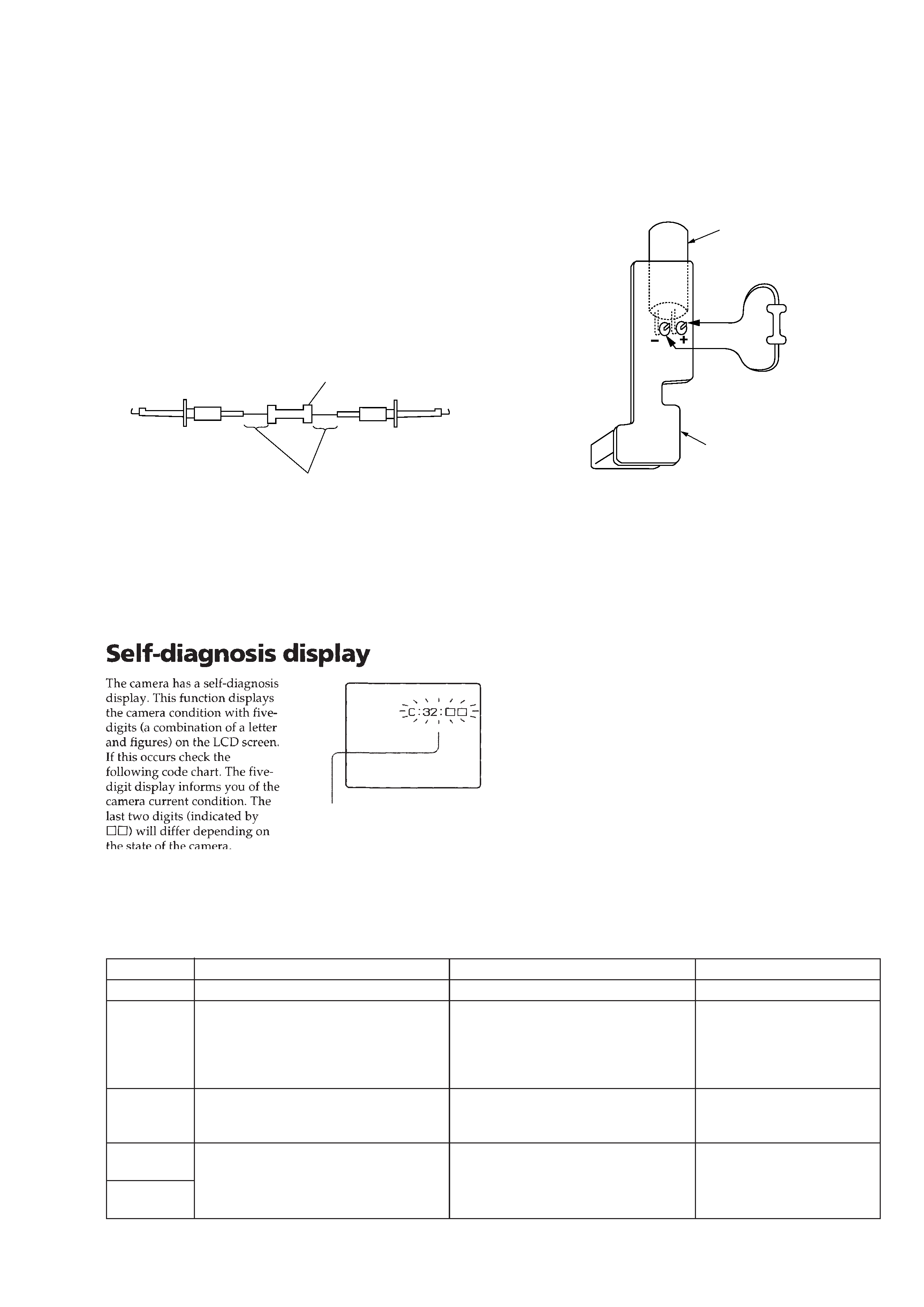
[Discharging of the FLASH unit's charging capacitor]
The charging capacitor of the FLASH unit is charged up to the
maximum 300 V potential.
There is a danger of electric shock by this high voltage when the
battery is handled by hand. The electric shock is caused by the
charged voltage which is kept without discharging when the main
power of the MVC-FD5/FD7 is simply turned off. Therefore, the
remaining voltage must be discharged as described below.
Preparing the Short Jig
To preparing the short jig. a small clip is attached to each end of a
resistor of 1k
/1W (1-215-869-11)
Wrap insulating tape fully around the leads of the resistor to prevent
electrical shock.
1k
/1W
Wrap insulating tape.
Charge capacitor
Short jig
Flash unit
SERVICE NOTE
Discharging the Capacitor
Short-circuit between the positive and the negative terminals of
charged capacitor with the short jig about 10 seconds.
[Description on Self-diagnosis Display]
Note : The "Self-diagnosis" data is backed up by the coin lithium
battery.The data will be lost and initialized when the coin
lithium battery is removed.
Note : The MVC-FD7 model only.
Display Code
C:32:01
C:13:01
E:91:01
E:61:00
E61:10
Countermeasure
Turn off the main power then back on.
Replace the floppy disk.
Format the floppy disk with the MVC-
FD5/FD7.
Checking of flash unit or replacement of
flash unit
Checking of lens drive circuit
Cause
Defective floppy disk.
· The type of floppy disk that cannot be
used by this machine, is inserted.
(Such as 2DD)
· Data is damaged.
· Unformatted disk is inserted.
Abnormality when flash is being
charged.
When failed in the focus initialization.
(Note)
Caution Display During Error
DRIVE ERROR
DISK ERROR
Flash LED
Flash display
Flashing at 3.2 Hz
--
Self-diagnosis display
· C:
:
The contents which can be handled
by customer, are displayed.
· E:
:
The contents which can be handled
by engineer, are displayed.