MVC-FD51
US Model
Canadian Model
AEP Model
UK Model
E Model
Hong Kong Model
Australian Model
SERVICE MANUAL
DIGITAL STILL CAMERA
MICROFILM
FLASH
Recording distance
limitations
(
)
This Service Manual covers only differences from the
MVC-FD5.
In performing repair, refer also to the MVC-FD5/FD7
Service Manual (9-973-972-XX)
The Hong Kong and Australian model are same as E
model, and therefore refer to the E model when per-
forming the repair.
Differences Manual
MVC-FD5
Standard
2~4m
MVC-FD51
2 times faster
50cm~3m
FDD
(Recording speed)
PICTURE EFFECT
· Main differences
r
(SEE PAGE
): Pages on the original service manual.
Q
: Points added parts.
q
: Points deleted parts.
oe
: Points changed parts.
Ver 1.1 1998. 10
With SUPPLEMENT 1
(9-974-075-81)
-- 2 --
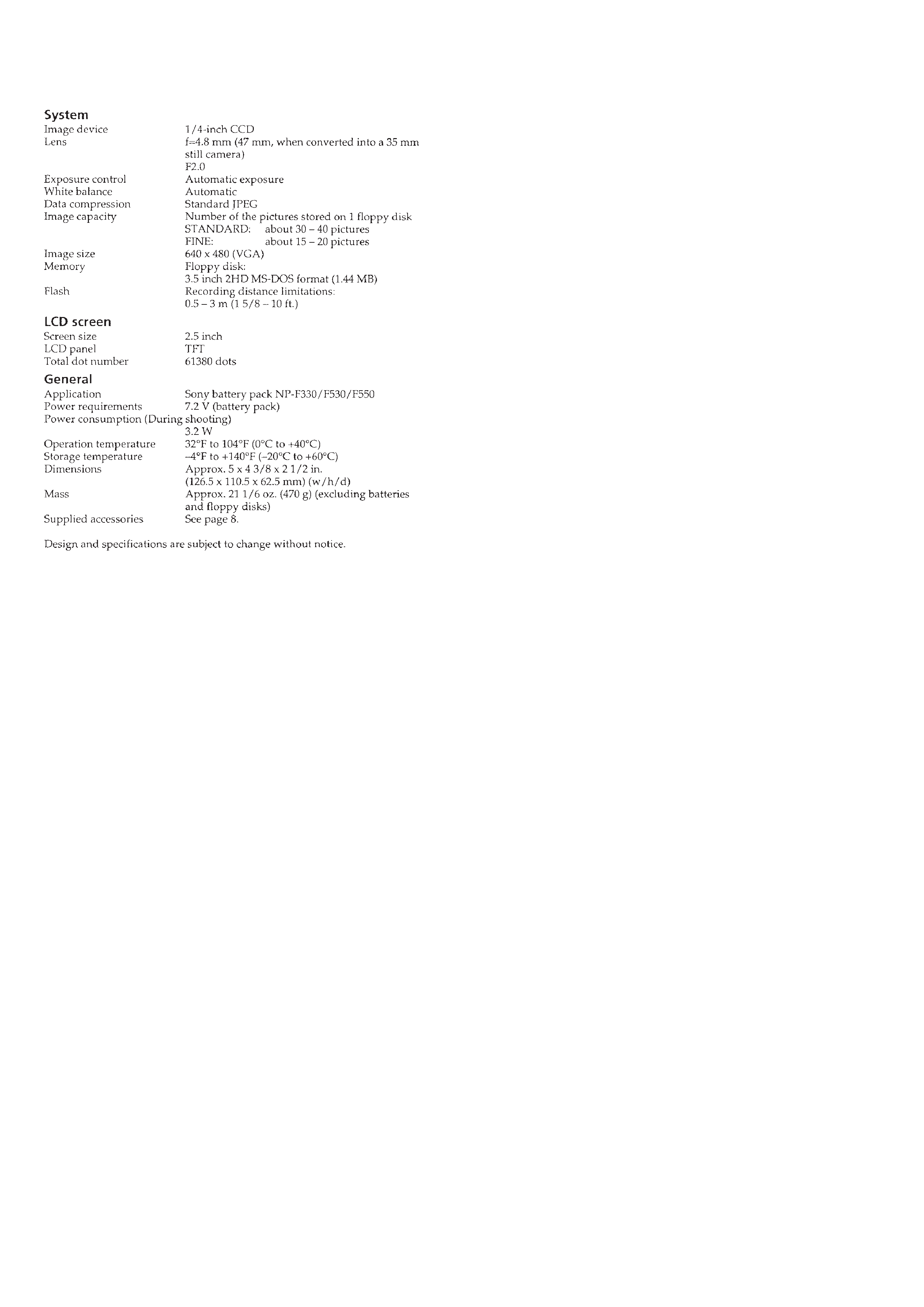
SPECIFICATIONS

-- 3 --
TABLE OF CONTENTS
SERVICE NOTE ····································································· 4
1.
GENERAL
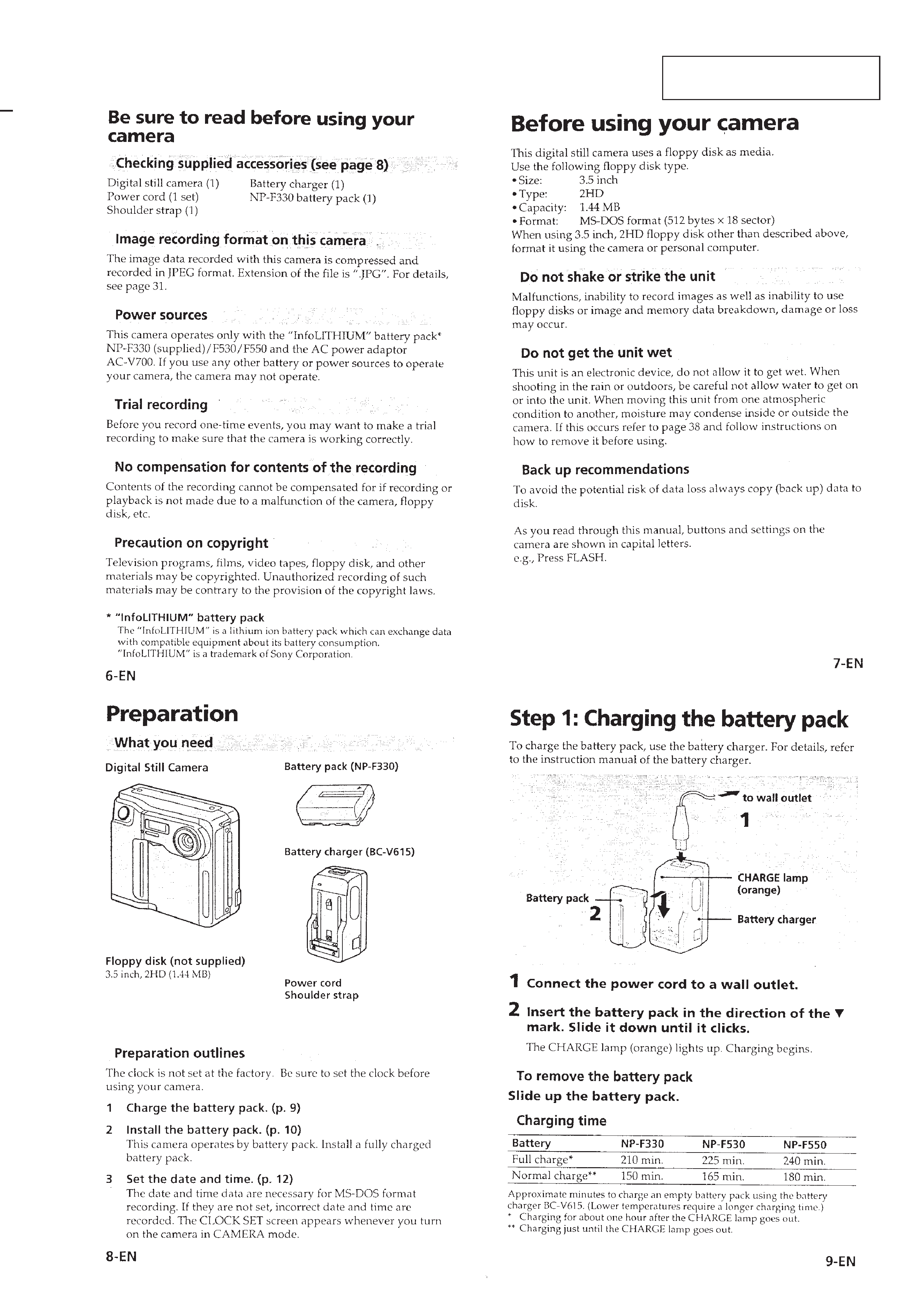
Be sure to read before using your camera ······························ 1-1
Before using your camera ······················································· 1-1
Preparation ·············································································· 1-1
Step 1: Charging the battery pack ·········································· 1-1
Step 2: Installing the battery pack ·········································· 1-2
Step 3: Setting the date and time ············································ 1-2
Recording images ··································································· 1-3
Watching images on the LCD screen ····································· 1-4
Viewing images using a personal computer ··························· 1-7
Changing the mode settings ··················································· 1-7
Enjoying Picture effect ··························································· 1-8
Changing the lithium battery in the camera ··························· 1-8
Precautions ············································································· 1-8
Troubleshooting ······································································ 1-9
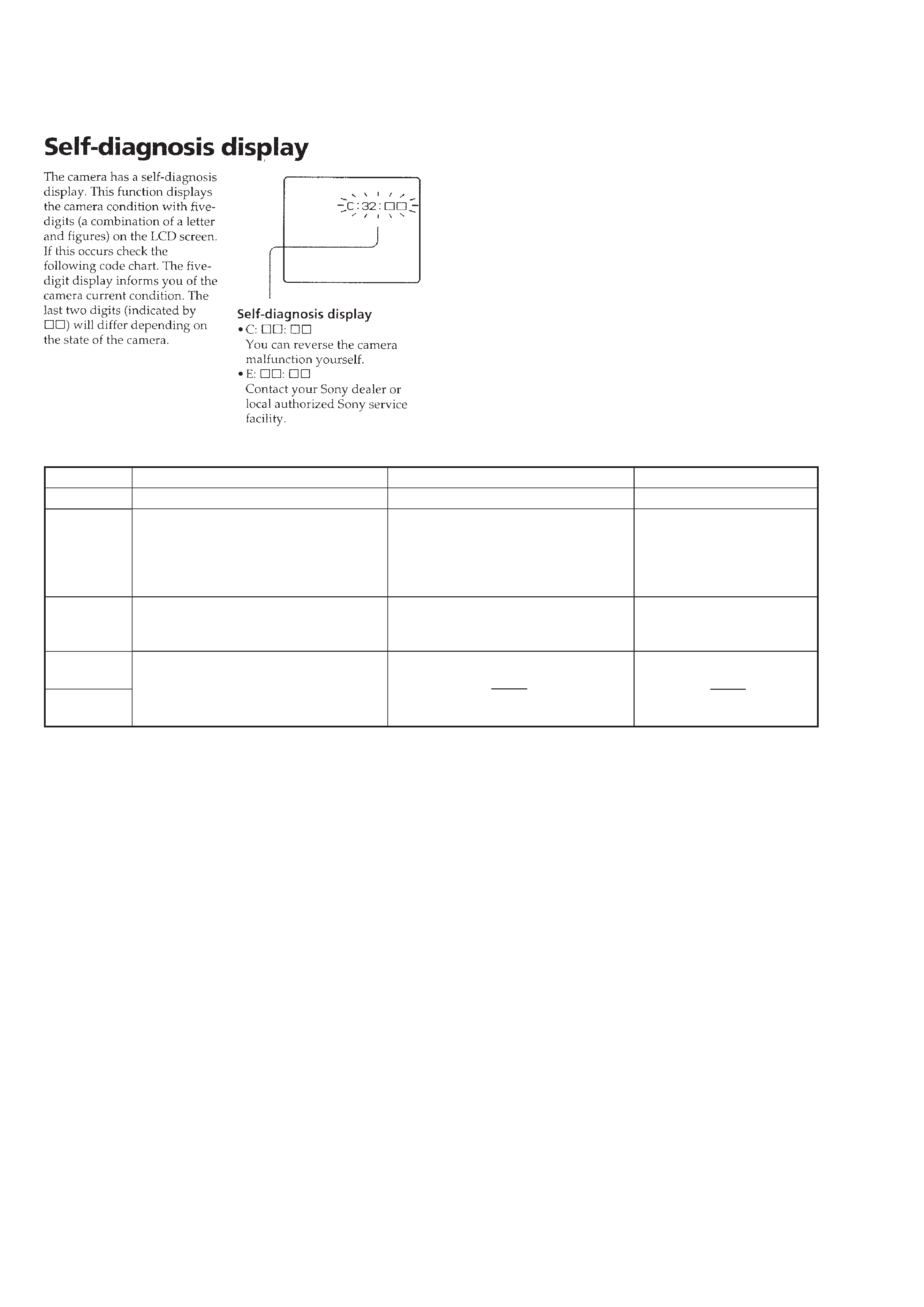
Self-diagnosis diaplay ···························································· 1-9
Parts identification ·································································· 1-10
2.
PRINTED WIRING BOARDS AND
SCHEMATIC DIAGRAMS
2-1.
PRINTED WIRING BOARDS AND
SCHEMATIC DIAGRAMS ········································· 2-1
· CD-176 (CCD IMAGER)
PRINTED WIRING BOARD AND
SCHEMATIC DIAGRAM ·························· 2-1
· FC-63 (CAMERA (1)),(FDD INTERFACE),
PK-42 (MODE KEY SWITCH)
SCHEMATIC DIAGRAM ·························· 2-5
3.
DIFFERENT PARTS LIST
3-1.
EXPLODED VIEWS ··················································· 3-1
3-1-1. CABINET (FRONT) SECTION ·································· 3-1
3-1-2. CABINET (REAR) SECTION ···································· 3-2
3-2.
ELECTRICAL PARTS LIST ······································· 3-3
3-3.
ACCESSORIES & PACKING MATERIALS ·············· 3-3
4.
ADJUSTMENTS
4-1.
CAMERA SECTION ADJUSTMENT ························ 4-1
1-1.
PREPARATIONS BEFORE ADJUSTMENT ·············· 4-1
1-1-6. Page F Address List ······················································ 4-1
1-1-7. Page E Address List ······················································ 4-4
1-2.
CAMERA SYSTEM ADJUSTMENTS ······················· 4-5
1.
Adjustment points when
major parts have been replaced ···································· 4-5
2.
Power supply voltage check (FC-63 board) ················· 4-5
3.
Preparation for adjustment ··········································· 4-5
4.
Initialization of page F data ·········································· 4-6
5.
Modification of Page F Data ········································ 4-6
6.
Modification of Page E Data ········································ 4-6
1-4.
SYSTEM CONTROL SYSTEM ADJUSTMENTS ···· 4-7
6.
Key input check (A/D port) ·········································· 4-7
-- 4 --
Display Code
C:32:01
C:13:01
E:91:01
E:61:00
E:61:10
SERVICE NOTE
[Description on Self-diagnosis Display]
Note : The "Self-diagnosis" data is backed up by the coin lithium
battery.The data will be lost and initialized when the coin
lithium battery is removed.
Countermeasure
Change the disc. Then turn the power off and on again.
Replace the floppy disk.
Format the floppy disk with the MVC-
FD51.
Checking of flash unit or replacement of
flash unit.
Checking of lens drive circuit.
Cause
Defective floppy disk.
· The type of floppy disk that cannot be
used by this machine, is inserted.
(Such as 2DD)
· Data is damaged.
· Unformatted disk is inserted.
Abnormality when flash is being
charged.
Caution Display During Error
DRIVE ERROR
DISK ERROR
Flash LED
Flash display
Flashing at 3.2 Hz
1-1
MVC-FD51
SECTION 1
GENERAL
This section is extracted fromMVC-
FD51 instruction manual.