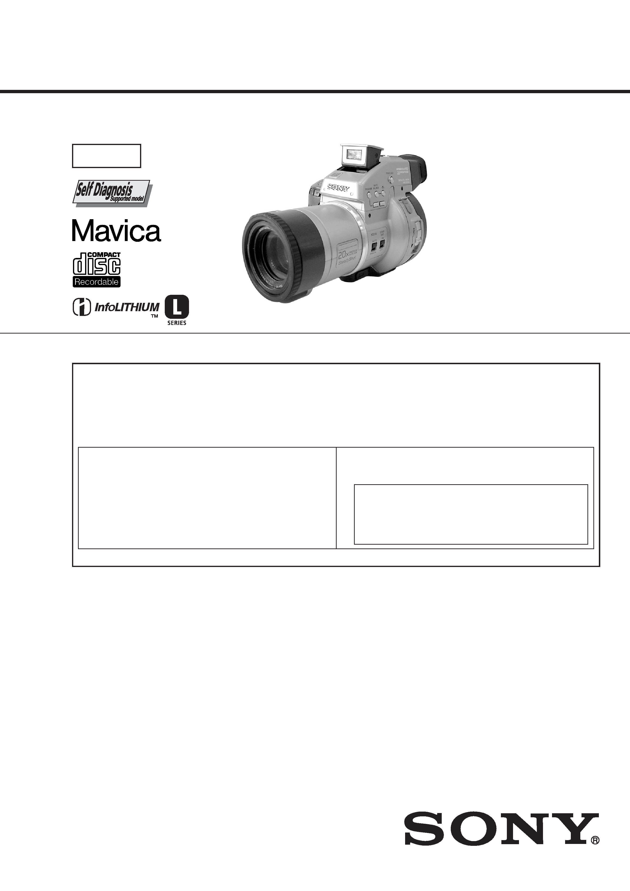
MVC-CD1000
US Model
Canadian Model
AEP Model
UK Model
E Model
Australian Model
Japanese Model
SERVICE MANUAL
DIGITAL STILL CAMERA
This service manual contains information for japanese model as well.
Level 2
SPECIFICATIONS
On the SY-060 board and the DDX-G2000 COMPLETE ASSEMBLY (Including the MD-082 Board)
This service manual provides the information on the premised of the circuit board replacement service and not intended
repair inside the SY-062 board in case of trouble. It is also premised that the mechanism deck DDX-G2000 COMPLETE
ASSEMBLY (including the MD-082 board) shall be exchanged as an assembly in case of trouble.
Therefore, disassembling procedure and exploded view of the DDX-G2000 COMPLETE ASSEMBLY are not shown. The
block diagram, schematic diagram, printed wiring board and electrical parts list of the SY-062 board are also not shown.
Note that the following pages are lacking intentionally.
The above-described information is shown in service manual Level 3.
SY-062 board
Block diagram ............................... Page 3-19 to 3-22
Schematic diagram ....................... Page 4-15 to 4-22
Printed wiring board ..................... Page 4-11 to 4-14
Electrical parts list ........................ Page 6-16 to 6-18
DDX-G2000 COMPLETE ASSEMBLY
Disassembly ................................. Page 2-12 to 2-13
Exploded view .............................. Page 6-8
MD-082 board
Block diagram ............................ Page 3-23 to 3-28
Schematic diagram .................... Page 4-27 to 4-36
Printed wiring board ................... Page 4-23 to 4-26
Electrical parts list ...................... Page 6-11 to 6-16
System
Image device
1/2.7 type color CCD
Lens
10
× zoom lens
f = 1/4 2 3/8 in (6.0
60.0 mm) (1 9/16 15 3/8 in
(39 390 mm) when
converted into a 35 mm still
camera)
F = 2.8
Exposure control
Automatic exposure
White balance
Automatic, Indoor, Outdoor,
One-push
Data compression
system
Movie: MPEG1
Still:
JPEG, TIFF, GIF (in TEXT
mode)
Audio (with still image):
MPEG AUDIO (Monaural)
Recording medium
8 cm CD-R
Flash
Recommended recording
distance:
23 5/8 in to 8 1/3 feet (0.6 m
to 2.5 m)
Drive
Read: Maximum
×8
Write:
×4
Readout
Noncontact optical readout
(using semiconductor laser)
Laser
Wavelength: 777 to 787 nm
NA: 0.5
Maximum output: 23 mW
Emission duration: 600 ns
Input and Output
connector
A/V OUT (MONO) jack
(Monaural)
Minijack Video:
1 Vp-p, 75
, unbalanced,
sync negative
Audio: 327 mV (at a 47 k
load)
Output impedance: 2.2 k
DIGITAL I/O jack
4-pin connector
External flash jack
Minijack
LCD screen
LCD panel
TFT (Thin Film Transistor
active matrix) drive
LCD size
2.5 type
Total number of dots
123 200 (560
×220) dots
Viewfinder
LCD panel
TFT (Thin Film Transistor
active matrix) drive
Total number of dots
180 000 (800
×225) dots
-- Continued on next page --
Ver 1.0 2000. 07
-- 2 --
SAFETY-RELATED COMPONENT WARNING!!
COMPONENTS IDENTIFIED BY MARK 0 OR DOTTED LINE WITH
MARK 0 ON THE SCHEMATIC DIAGRAMS AND IN THE PARTS
LIST ARE CRITICAL TO SAFE OPERATION. REPLACE THESE
COMPONENTS WITH SONY PARTS WHOSE PART NUMBERS
APPEAR AS SHOWN IN THIS MANUAL OR IN SUPPLEMENTS
PUBLISHED BY SONY.
ATTENTION AU COMPOSANT AYANT RAPPORT
À LA SÉCURITÉ!
LES COMPOSANTS IDENTIFÉS PAR UNE MARQUE 0 SUR LES
DIAGRAMMES SCHÉMATIQUES ET LA LISTE DES PIÈCES SONT
CRITIQUES POUR LA SÉCURITÉ DE FONCTIONNEMENT. NE
REMPLACER CES COMPOSANTS QUE PAR DES PIÈSES SONY
DONT LES NUMÉROS SONT DONNÉS DANS CE MANUEL OU
DANS LES SUPPÉMENTS PUBLIÉS PAR SONY.
1.
Check the area of your repair for unsoldered or poorly-soldered
connections. Check the entire board surface for solder splashes
and bridges.
2.
Check the interboard wiring to ensure that no wires are
"pinched" or contact high-wattage resistors.
3.
Look for unauthorized replacement parts, particularly
transistors, that were installed during a previous repair. Point
them out to the customer and recommend their replacement.
4.
Look for parts which, through functioning, show obvious signs
of deterioration. Point them out to the customer and
recommend their replacement.
5.
Check the B+ voltage to see it is at the values specified.
6.
Flexible Circuit Board Repairing
· Keep the temperature of the soldering iron around 270°C
during repairing.
· Do not touch the soldering iron on the same conductor of the
circuit board (within 3 times).
· Be careful not to apply force on the conductor when soldering
or unsoldering.
SAFETY CHECK-OUT
After correcting the original service problem, perform the following
safety checks before releasing the set to the customer.
CAUTION
Use of controls or adjustments or performance
procedures other than those specified herein may
result in hazardous radiation exposure.
General
Application
Sony battery pack NP-F550
Power requirements
8.4 V
Power consumption
(During shooting)
4.9 W (When using the LCD
screen)
4.5 W (When using the
viewfinder)
Operation temperature
32
°F to 104 °F (0 °C to
40
°C)
Storage temperature
4
°F to +140 °F (20 °C to
+60
°C)
Maximum dimensions
5 1/2
×5 1/4×8 3/8 in
(137
×131×212 mm) (w/h/d)
Mass
Approx. 35 oz (990 g)
(including battery, disc and
lens cap, etc.)
Built-in microphone
Electret condenser
microphone
Built-in speaker
Dynamic speaker
AC-L10A/L10B/L10C
AC power adaptor
Power requirements
100 V to 240 V AC,
50/60 Hz
Rated output voltage
DC 8.4 V, 1.5 A in operating
mode
Operation temperature
32
°F to 104 °F (0 °C to
40
°C)
Storage temperature
4
°F to +140 °F (20 °C to
+60
°C)
Maximum dimensions
5
×1 9/16×2 1/2 in
(125
×39×62 mm) (w/h/d)
Mass
Approx. 10 oz (280 g)
NP-F550 battery pack
Used battery
Lithium ion battery
Maximum voltage
DC 8.4 V
Nominal voltage
DC 7.2 V
Capacity
10.8 Wh (1 500 mAh)
Accessories
AC-L10A/L10B/L10C
AC power adaptor (1)
Power cord (mains lead) (1)
NP-F550 battery pack (1)
A/V connecting cable (1)
USB cable (1)
8 cm CD adaptor (1)
Mavica disc (5)
Shoulder strap (1)
Lens cap (1)
Lens cap strap (1)
CD-ROM (3)
Operating instructions (3)
Design and specifications
are subject to change
without notice.

-- 3 --
TABLE OF CONTENTS
SERVICE NOTE ····································································· 6
1.
GENERAL
Getting started
Identifying the parts ······························································· 1-1
Preparing the power supply ··················································· 1-1
Setting the date and time ························································ 1-2
Inserting a disc ······································································· 1-3
Basic operations
B Recording
Initializing a disc (INITIALIZE) ··········································· 1-3
Recording still images ··························································· 1-4
Recording moving images ····················································· 1-5
B Playback
Playing back still images ······················································· 1-5
Playing back moving images ················································· 1-6
Viewing images using a personal computer ·························· 1-6
Image file storage destinations and image file names ··········· 1-9
Advanced operations
Before performing advanced operations
How to use the PLAY/STILL/MOVIE selector ····················· 1-9
How to use the control button ················································ 1-9
How to change the menu settings ········································ 1-10
B Various recording
Setting the image size (IMAGE SIZE) ································ 1-11
Recording still images for e-mail (E-MAIL) ······················· 1-11
Adding audio files to still images (VOICE) ························ 1-11
Recording text documents (TEXT) ····································· 1-11
Recording uncompressed images (TIFF) ····························· 1-11
Recording images in macro ················································· 1-12
Focusing manually ······························································· 1-12
Using the PROGRAM AE function ····································· 1-12
Using the Spot lightmetering function ······························· 1-12
Adjusting the exposure (EXPOSURE) ································ 1-12
Adjusting the white balance (WHITE BALANCE) ············ 1-12
Recording the date and time on the still image (DATE/TIME) · 1-13
Enjoying picture effects (PICTURE EFFECT) ··················· 1-13
B Various playback
Playing back six images at once (INDEX) ·························· 1-13
Enlarging a part of the still image (Zoom and trimming) ···· 1-13
Rotating a still image (ROTATE) ········································· 1-14
Playing back the still images in order (SLIDE SHOW) ······ 1-14
Viewing images on a TV screen ·········································· 1-14
B Editing
Preventing accidental erasure (PROTECT) ························· 1-14
Deleting images (DELETE) ················································ 1-14
Changing the recorded still image size (RESIZE) ··············· 1-15
Selecting still images to print (PRINT MARK) ·················· 1-15
Additional information
Precautions ··········································································· 1-15
On discs ··············································································· 1-16
Using your camera abroad ··················································· 1-16
Troubleshooting ··································································· 1-16
Warning and notice messages ·············································· 1-17
Self-diagnosis display ·························································· 1-17
LCD screen/viewfinder indicators ······································· 1-18
2.
DISASSEMBLY
2-1.
LCD SECTION (PK-051 BOARD) ································ 2-2
2-2.
CABINET (UPPER) SECTION ······································ 2-3
2-3.
FLASH UNIT ·································································· 2-3
2-4.
EVF SECTION ································································ 2-4
2-5.
CABINET (F) SECTION,
CABINET (CENTER) SECTION ··································· 2-5
2-6.
LENS BLOCK ASSEMBLY,
CONTROL SWITCH BLOCK (FS52K),
CONTROL SWITCH BLOCK (JK52K) ························ 2-5
2-7.
CONTROL SWITCH BLOCK (ZM52K) ······················· 2-6
2-8.
VP-051, SE-115 BOARDS ············································· 2-6
2-9.
SY-060, VC-246 BOARDS ············································· 2-7
2-10. MECHANISM DECK (DDX-G2000 COMPLETE
ASSEMBLY), CONTROL SWITCH BLOCK (AJ52K) ·· 2-8
2-11. LID CABINET SECTION,
CONTROL SWITCH BLOCK (MP52K) ······················· 2-9
2-12. CD-272 BOARD, LENS ASSEMBLY, VAP ASSEMBLY ·· 2-9
2-13. CIRCUIT BOARDS LOCATION ································· 2-10
2-14. FLEXIBLE BOARDS LOCATION ······························ 2-11
3.
BLOCK DIAGRAMS
3-1.
OVERALL BLOCK DIAGRAM-1 ································· 3-1
OVERALL BLOCK DIAGRAM-2 ································· 3-3
3-2.
STEADY SHOT BLOCK DIAGRAM ···························· 3-5
3-3.
MODE CONTROL BLOCK DIAGRAM ······················· 3-7
3-4.
LCD BLOCK DIAGRAM ·············································· 3-9
3-5.
EVF BLOCK DIAGRAM ············································· 3-11
3-6.
POWER BLOCK DIAGRAM-1 ··································· 3-13
POWER BLOCK DIAGRAM-2 ··································· 3-15
POWER BLOCK DIAGRAM-3 ··································· 3-17
4.
PRINTED WIRING BOARDS AND
SCHEMATIC DIAGRAMS
4-1.
FRAME SCHEMATIC DIAGRAM (1/2) ······················· 4-1
FRAME SCHEMATIC DIAGRAM (2/2) ······················· 4-3
4-2.
PRINTED WIRING BOARDS AND
SCHEMATIC DIAGRAMS ············································ 4-5
· CD-272 (CCD IMAGER)
PRINTED WIRING BOARD ························· 4-7
· CD-272 (CCD IMAGER)
SCHEMATIC DIAGRAM ······························ 4-9
· CONTROL SWITCH BLOCK (JK52K, FS52K)
SCHEMATIC DIAGRAM ···························· 4-10
· MK-015 (EYE SENSOR)
PRINTED WIRING BOARD ······················· 4-37
· MK-015 (EYE SENSOR)
SCHEMATIC DIAGRAM ···························· 4-38
· VC-246 (LENS DRIVE, VIDEO AMP, BUS SWITCH,
LINE/SPEAKER AMP, HI CONTROL,
DC/DC CONVERTER-1,2)
PRINTED WIRING BOARD ······················· 4-39
· VC-246 (LENS DRIVE)(1/8)
SCHEMATIC DIAGRAM ···························· 4-43
· VC-246 (VIDEO AMP)(2/8)
SCHEMATIC DIAGRAM ···························· 4-45
· VC-246 (CAMERA/MD INTERFACE)(3/8)
SCHEMATIC DIAGRAM ···························· 4-47
· VC-246 (LINE/SPEAKER AMP)(4/8)
SCHEMATIC DIAGRAM ···························· 4-49
· VC-246 (HI CONTROL)(5/8)
SCHEMATIC DIAGRAM ···························· 4-51
· VC-246 (DC/DC CONVERTER-1)(6/8)
SCHEMATIC DIAGRAM ···························· 4-53
· VC-246 (DC/DC CONVERTER-2)(7/8)
SCHEMATIC DIAGRAM ···························· 4-55
Schematic diagram and printed wiring board of the SY-
062 and MD-082 boards are not shown.
Pages from 4-11 to 4-36 are not shown.
Founctional block diagrams are not shown.
Pages from 3-19 to 3-28 are not shown.
Disassembling procedure of Mechanism deck (DDX-
G2000 COMPLETE ASSEMBLY) are not shown.
Pages 2-12 and 2-13 are not shown.

-- 4 --
· VC-246 (CONNECTOR)(8/8)
SCHEMATIC DIAGRAM ···························· 4-57
· VP-051 (STEADY SHOT, LENS MOTOR DRIVE)
PRINTED WIRING BOARD ······················· 4-59
· VP-051 (STEADY SHOT, LENS MOTOR DRIVE)
SCHEMATIC DIAGRAM ···························· 4-61
· SE-115 (PITCH/YAW SENSOR)
PRINTED WIRING BOARD ······················· 4-63
· SE-115 (PITCH/YAW SENSOR)
SCHEMATIC DIAGRAM ···························· 4-65
· SW-342 (USER CONTROL)
PRINTED WIRING BOARD ······················· 4-67
· SW-342 (USER CONTROL),
CONTROL SWITCH BLOCK (LC52K)
SCHEMATIC DIAGRAMS ·························· 4-69
· PK-051 (LCD DRIVE, BACK-LIGHT,
TIMING GENERATOR)
PRINTED WIRING BOARD ······················· 4-71
· PK-051 (LCD DRIVE, BACK-LIGHT)(1/2)
SCHEMATIC DIAGRAM ···························· 4-75
· PK-051 (TIMING GENERATOR)(2/2)
SCHEMATIC DIAGRAM ···························· 4-77
· LB-066 (BACK-LIGHT)
PRINTED WIRING BOARD ······················· 4-79
· LB-066 (BACK-LIGHT)
SCHEMATIC DIAGRAM ···························· 4-80
· VF-144 (LCD DRIVE, TIMING GENERATOR)
PRINTED WIRING BOARD ······················· 4-81
· VF-144 (LCD DRIVE)(1/2)
SCHEMATIC DIAGRAM ···························· 4-83
· VF-144 (TIMING GENERATOR)(2/2)
SCHEMATIC DIAGRAM ···························· 4-85
· CONTROL SWITCH BLOCK
(AE52K, ZM52K, AJ52K, MP52K)
SCHEMATIC DIAGRAM ···························· 4-87
4-3.
WAVEFORMS ······························································ 4-89
4-4.
MOUNTED PARTS LOCATION ································· 4-94
5.
ADJUSTMENTS
1.
Before Starting Adjustment ············································· 5-1
1-1.
Adjusting items when replacing main parts and boards ·· 5-2
5-1.
ADJUSTMENT ······························································· 5-3
1-1.
PREPARATIONS BEFORE ADJUSTMENT ················· 5-3
1-1-1. List of Service Tools ························································ 5-3
1-1-2. Preparations ····································································· 5-4
1-1-3. Discharging of the Flashlight Power Supply ··················· 5-5
1-1-4. Precaution ········································································ 5-7
1.
Setting the Switch ···························································· 5-7
2.
Order of Adjustments ······················································ 5-7
3.
Subjects ··········································································· 5-7
1-2.
INITIALIZATION OF B, D, E, F, 7 PAGE DATA ········· 5-8
1-2-1. INITIALIZATION OF D PAGE DATA ·························· 5-8
1.
Initializing the D Page Data ············································ 5-8
2.
Modification of D Page Data ··········································· 5-8
3.
D Page Table ···································································· 5-8
1-2-2. Initializing the B, E, F, 7 Page Data ································ 5-9
1.
Initializing the B, E, F, 7 Page Data ································ 5-9
2.
Modification of B, E, F, 7 Page Data ······························· 5-9
3.
F Page Table ·································································· 5-10
4.
7 Page Table ··································································· 5-11
5.
E Page Table ·································································· 5-12
6.
B Page Table ·································································· 5-12
1-3.
VIDEO SYSTEM ADJUSTMENTS ····························· 5-13
1.
Video Output Level Adjustment (VC-246 board) ········· 5-13
1-4.
CAMERA SYSTEM ADJUSTMENTS ························ 5-14
1.
Zoom Key Center Adjustment ······································· 5-14
2.
HALL Adjustment ························································· 5-14
3.
Flange Back Adjustment (Using Minipattern Box) ······· 5-15
4.
Flange Back Adjustment
(Using Flange Back Adjustment Chart) ························ 5-16
4-1.
Flange Back Adjustment (1) ·········································· 5-16
4-2.
Flange Back Adjustment (2) ·········································· 5-16
5.
Flange Back Check ························································ 5-17
6.
F No. Standard Data Input ············································· 5-17
7.
Mechanical Shutter Adjustment ···································· 5-17
8.
Picture Frame Setting ···················································· 5-18
9.
Light Level Adjustment and ND Shutter Check ············ 5-19
10.
Mixed Color Cancel Adjustment ··································· 5-19
11.
Auto White Balance Standard Data Input ····················· 5-20
12.
White Balance ND Filter Compensation ······················· 5-20
13.
Auto White Balance Adjustment ··································· 5-21
14.
Color Reproduction Adjustment (ND Filter OFF) ········ 5-21
15.
Color Reproduction Adjustment (ND Filter ON) ·········· 5-22
16.
Color Reproduction Check ············································ 5-23
17.
White Balance Check ···················································· 5-24
18.
Strobe White Balance Adjustment ································· 5-25
19.
Strobe Light Level and White Balance Check ·············· 5-25
20.
CCD Black Defect Compensation ································· 5-26
21.
CCD White Defect Compensation ································ 5-26
22.
Steady shot adjustment ·················································· 5-27
22-1. Steady Shot Adjustment (1) ··········································· 5-27
22-2. Steady Shot Adjustment (2) ··········································· 5-28
1-5.
LCD SYSTEM ADJUSTMENT ··································· 5-29
1.
LCD Initial Data Input ·················································· 5-29
2.
VCO Adjustment (PK-051 board) ································· 5-30
3.
D Range Adjustment (PK-051 board) ··························· 5-30
4.
Bright Adjustment (PK-051 board) ······························· 5-31
5.
Contrast Adjustment (PK-051 board) ···························· 5-31
6.
Color Adjustment (PK-051 board) ································ 5-32
7.
V-COM Level Adjustment (PK-051 board) ·················· 5-32
8.
V-COM Adjustment (PK-051 board) ···························· 5-33
9.
White Balance Adjustment (PK-051 board) ·················· 5-33
1-6.
COLOR ELECTRONIC VIEWFINDER SYSTEM
ADJUSTMENT ····························································· 5-34
1.
Initial Data Input ··························································· 5-34
2.
VCO Adjustment (VF-144 board) ································· 5-35
3.
Bright Adjustment (VF-144 board) ······························· 5-35
4.
Contrast Adjustment (VF-144 board) ···························· 5-36
5.
Backlight Consumption Current Adjustment
(VF-144 board) ······························································ 5-36
6.
White Balance Adjustment (VF-144 board) ·················· 5-37
7.
Eye Sensor Adjustment (VF-144 board) ······················· 5-37
1-7.
SYSTEM CONTROL SYSTEM ADJUSTMENT ········ 5-38
1.
Battery End Adjustment (VC-246 board) ······················ 5-38
2.
Serial No. Input ····························································· 5-39
5-2.
SERVICE MODE ·························································· 5-40
2-1.
ADJUSTMENT REMOTE COMMANDER ················ 5-40
1.
Using the Adjustment Remote Commander ·················· 5-40
2.
Precautions Upon Using the Adjustment Remote
Commander ··································································· 5-40
2-2.
DATA PROCESS ··························································· 5-41
2-3.
SERVICE MODE ·························································· 5-42
1.
Setting the Test Mode ···················································· 5-42
2.
Bit Value Discrimination ··············································· 5-42
3.
Emergency Memory Address of Flash Unit ·················· 5-42
4.
Record of Use check ······················································ 5-43
5.
Self Diagnosis Log check ·············································· 5-43
6.
Switch check (1) ···························································· 5-44
7.
Switch check (2) ···························································· 5-44
8.
LED check ····································································· 5-44
9.
Position sensor check (VP-051 board PH201) ·············· 5-45
10.
VAP (Active prism actuator) lock check ······················· 5-45

-- 5 --
6.
REPAIR PARTS LIST
6-1.
EXPLODED VIEWS ······················································ 6-1
6-1-1. OVERALL SECTION ····················································· 6-1
6-1-2. CABINET (UPPER) SECTION ······································ 6-2
6-1-3. EVF SECTION ································································ 6-3
6-1-4. CABINET (F) SECTION ················································ 6-4
6-1-5. LENS SECTION ····························································· 6-5
6-1-6. CABINET (CENTER) SECTION ··································· 6-6
6-1-7. LID CABINET SECTION ·············································· 6-7
6-2.
ELECTRICAL PARTS LIST ·········································· 6-9
Electrical parts list of the SY-062 and MD-082 boards
are not shown.
Pages from 6-11 to 6-18 are not shown.
* Color reproduction frame is shown on page 199.
Exploded view and parts list of DDX-G2000 COMPLETE
ASSEMBLY are not shown.
Page 6-8 is not shown.