SERVICE MANUAL
Ver 1.2 2004.04
MOBILE VIDEO SYSTEM
MV-7101DS
MODEL NUMBER LABEL
PRINTED MODEL NAME
DVD PLAYER
MV-7101DS
MV-101
OVERHEAD MONITOR
MV-7101DS
XVM-R70
CONNECTION BOX
XA-115
CORDLESS STEREO HEADPHONE
MDR-IF0140
MDR-IF0140
CARD REMOTE COMMANDER
RM-X135
US Model
·MV-7101DS is composed of following models.
For XVM-R70 (including XA-115), refer to the service manual
issued separately.
COMPONENT MODEL NAME
SPECIFICATIONS
DVD player MV-101
System
Laser
Semiconductor laser
Signal format system
NTSC
Audio characteristics
Frequency response
20 Hz to 20 kHz
Signal to noise ratio
90dB (A)
Hermonic distortion
0.03 %
Dynamic range
90dB
Wow and flutter
below measurable limits
( 0.001% W PEAK)
General
Outputs
Audio output
Video output
Optical output
Inputs
IR input
DV 12V input
Power requirements
12 V DC car battery
(negative ground)
Dimensions
Approx. 189
× 70 × 243 mm
(7 1/2
× 2 7/8 × 9 5/8 in)
(w/h/d)
Mass
Approx. 2.1 kg
(4 lb 11 oz)
Operating temperature 0
to 45
(32
to 113 )
Supplied accessories
Parts for installation and
connections (1 set)
Card remote commander
RM-X135
Operating Instructions (1 set)
Overhead Monitor XVM-R70
Monitor
System
Liquid crystal color display
Display
Manual flipdown panel
Drive system
TFT-LCD active matrix
system
Picture size
7 inches wide screen (16:9)
154
× 87 mm, 176 mm
(6 1/8
× 3 1/2 in, 7 in)
(w/h, d)
Picture segment
336,960 (w 1440
× h 234)
dots
Power requirements
12 V DC car battery
(negative ground)
Current drain
Approx. 800 mA
Dimensions
230
× 57 × 270 mm
(9 1/8
× 2 3/8 × 10 3/4 in)
(w/h/d)
Operating temperature 5
to 45
(41
to 113
)
Mass
Approx. 1.5 Kg (3 lb 5 oz)
Supplied accessories
Connection box XA-115 (1)
Monitor cable (5 m) (1)
Power supply cord (1)
DC-DC cord (3 m) (1)
Mounting plate (1)
Screws (4)
Tapping Screws (4)
Cordless Stereo headphone MDR-IF0140
General
Modulation system
Frequency modulation
Carrier frequency
Right 2.8 MHz
Left 2.3 MHz
Frequency response
18 - 22,000 Hz
Power source
DC 1.5 V (size AAA) dry
battery
Mass
Approx. 125 g (4.41 oz)
including battery
Design and specifications are subject to change
without notice.
Connection box XA-115
A/V Output
Output Impedance:
less than 220
less than 100 pF
Output Level:
0 dBs 3 dB
(0.775 V rms)
(Vol Max)
Video:
75
1Vp-p
A/V Input
× 3
Input Impedance:
more than 10 K
less than 1000 pF
Input Level:
1.3 dBs +0/-0.3 dB (0.775
V rms)
Video:
75
1 Vp-p
DC output
7.5 V (max 2 A)
Dimensions
150
× 42 × 80 mm
(6
× 11/16 × 3 1/4 in)
(w/h/d)
Mass
Approx. 260 g (9 oz)
9-877-405-03
Sony Corporation
2004D05-1
e Vehicle Company
© 2004.04
Published by Sony Engineering Corporation
2
MV-7101DS
Notes on chip component replacement
·Never reuse a disconnected chip component.
· Notice that the minus side of a tantalum capacitor may be dam-
aged by heat.
Flexible Circuit Board Repairing
·Keep the temperature of the soldering iron around 270 °C dur-
ing repairing.
· Do not touch the soldering iron on the same conductor of the
circuit board (within 3 times).
· Be careful not to apply force on the conductor when soldering
or unsoldering.
NOTES ON HANDLING THE OPTICAL PICK-UP
BLOCK OR BASE UNIT
SAFETY-RELATED COMPONENT WARNING!!
COMPONENTS IDENTIFIED BY MARK 0 OR DOTTED
LINE WITH MARK 0 ON THE SCHEMATIC DIAGRAMS
AND IN THE PARTS LIST ARE CRITICAL TO SAFE
OPERATION. REPLACE THESE COMPONENTS WITH
SONY PARTS WHOSE PART NUMBERS APPEAR AS
SHOWN IN THIS MANUAL OR IN SUPPLEMENTS PUB-
LISHED BY SONY.
The laser diode in the optical pick-up block may suffer electro-
static break-down because of the potential difference generated
by the charged electrostatic load, etc. on clothing and the human
body.
During repair, pay attention to electrostatic break-down and also
use the procedure in the printed matter which is included in the
repair parts.
The flexible board is easily damaged and should be handled with
care.
NOTES ON LASER DIODE EMISSION CHECK
Never look into the laser diode emission from right above when
checking it for adjustment. It is feared that you will lose your sight.
UNLEADED SOLDER
Boards requiring use of unleaded solder are printed with the lead-
free mark (LF) indicating the solder contains no lead.
(Caution: Some printed circuit boards may not come printed with
the lead free mark due to their particular size)
: LEAD FREE MARK
Unleaded solder has the following characteristics.
· Unleaded solder melts at a temperature about 40 °C higher than
ordinary solder.
Ordinary soldering irons can be used but the iron tip has to be
applied to the solder joint for a slightly longer time.
Soldering irons using a temperature regulator should be set to
about 350 °C.
Caution: The printed pattern (copper foil) may peel away if the
heated tip is applied for too long, so be careful!
· Strong viscosity
Unleaded solder is more viscou-s (sticky, less prone to flow)
than ordinary solder so use caution not to let solder bridges oc-
cur such as on IC pins, etc.
· Usable with ordinary solder
It is best to use only unleaded solder but unleaded solder may
also be added to ordinary solder.
CAUTION
Use of controls or adjustments or performance of procedures
other than those specified herein may result in hazardous ra-
diation exposure.
Ver 1.1
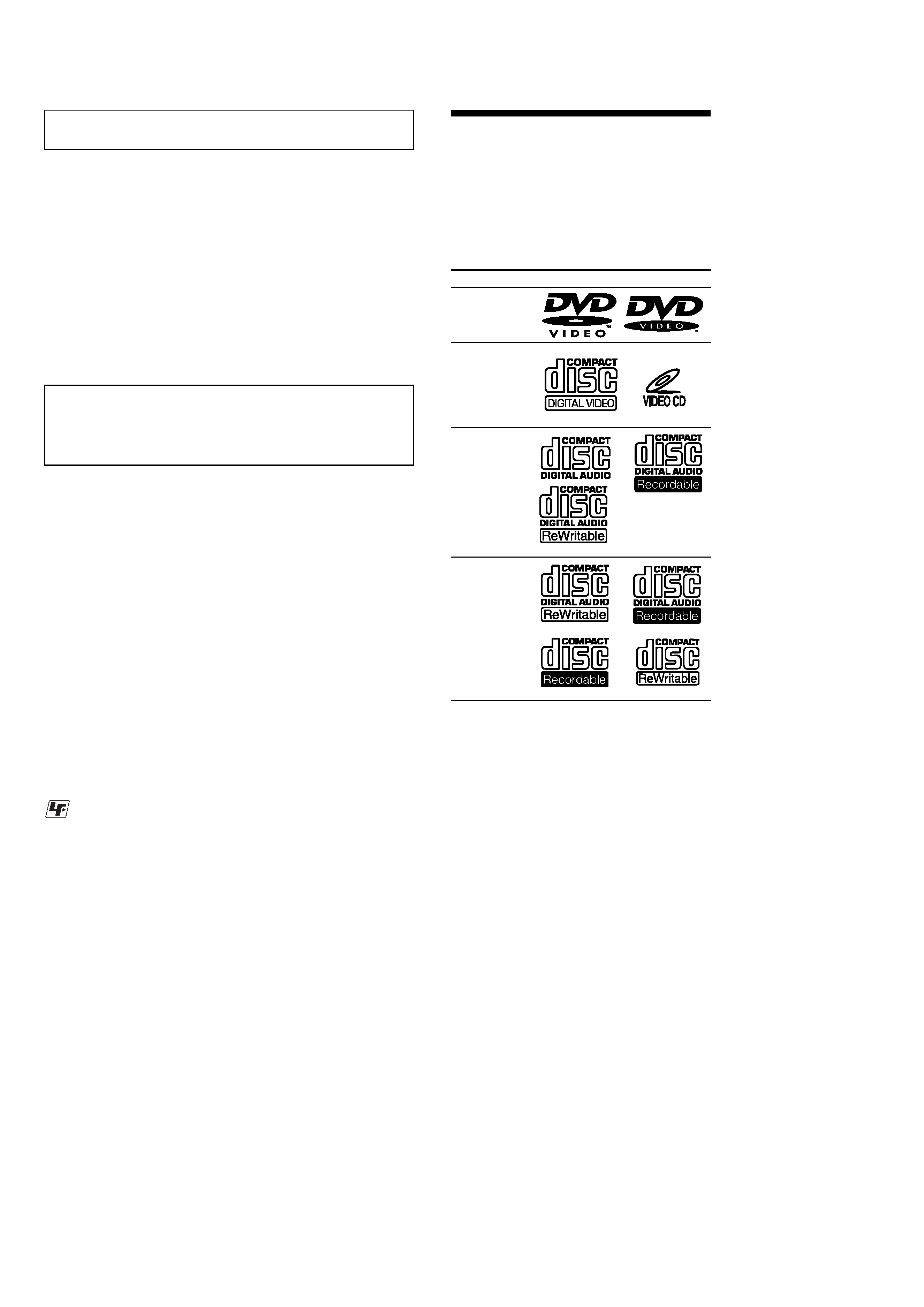
About discs this player can
play
This player can play 12 cm (4 7/10 in) disc only.
·DVD
·Video CD
·Audio CD
·CD-R/CD-RW
Disc type
Label on the disc
DVD Videos
Video CDs
Audio CDs
MP3 files
Notes on CD-Rs (recordable CDs)/
CD-RWs (rewritable CDs)
·Some CD-Rs/CD-RWs (depending on the
equipment used for its recording or the
condition of the disc) may not play on this
unit.
·You cannot play a CD-R/CD-RW that is not
finalized*.
·You can play MP3 files recorded on CD-
ROMs, CD-Rs, and CD-RWs.
* A process necessary for a recorded CD-R/CD-RW
disc to be played on the audio CD player. Notes
on CD-Rs (recordable CDs)/CD-RWs (rewritable
CDs)

3
MV-7101DS
TABLE OF CONTENTS
1.
GENERAL
Location of Controls .......................................................
4
2.
DISASSEMBLY
2-1. Disassembly Flow ........................................................... 11
2-2. Cabinet Front Assy .......................................................... 11
2-3. Cavity (Rear) ................................................................... 12
2-4. Case (Upper) ................................................................... 12
2-5. DVD MD Assy ................................................................ 13
2-6. Chassis (MD) Assy ......................................................... 13
2-7. SERVO Board, Mechanism Deck ................................... 14
2-8. TD-S-TOP-COVER ........................................................ 14
2-9. Loading Mechanism Assy ............................................... 15
2-10. Traverse Mechanism Assy .............................................. 15
3.
DIAGRAMS
3-1. Note for Printed Wiring Boards
and Schematic Diagrams ................................................ 17
3-2. Printed Wiring Boards KEY Section ....................... 18
3-3. Schematic Diagrams KEY Section .......................... 19
3-4. Printed Wiring Board POWER Section ................... 20
3-5. Schematic Diagram POWER Section ..................... 21
4.
EXPLODED VIEWS
4-1. Overall Section ................................................................ 23
4-2. Cabinet Front Assy Section ............................................ 24
4-3. Case (Lower) Assy Section ............................................. 25
4-4. DVD MD Assy Section ................................................... 26
4-5. Mechanism Deck Section-1 ............................................ 27
4-6. Mechanism Deck Section-2 ............................................ 28
4-7. Mechanism Deck Section-3 ............................................ 29
5.
ELECTRICAL PARTS LIST ............................... 30
Ver 1.1
4
MV-7101DS
Ver 1.1
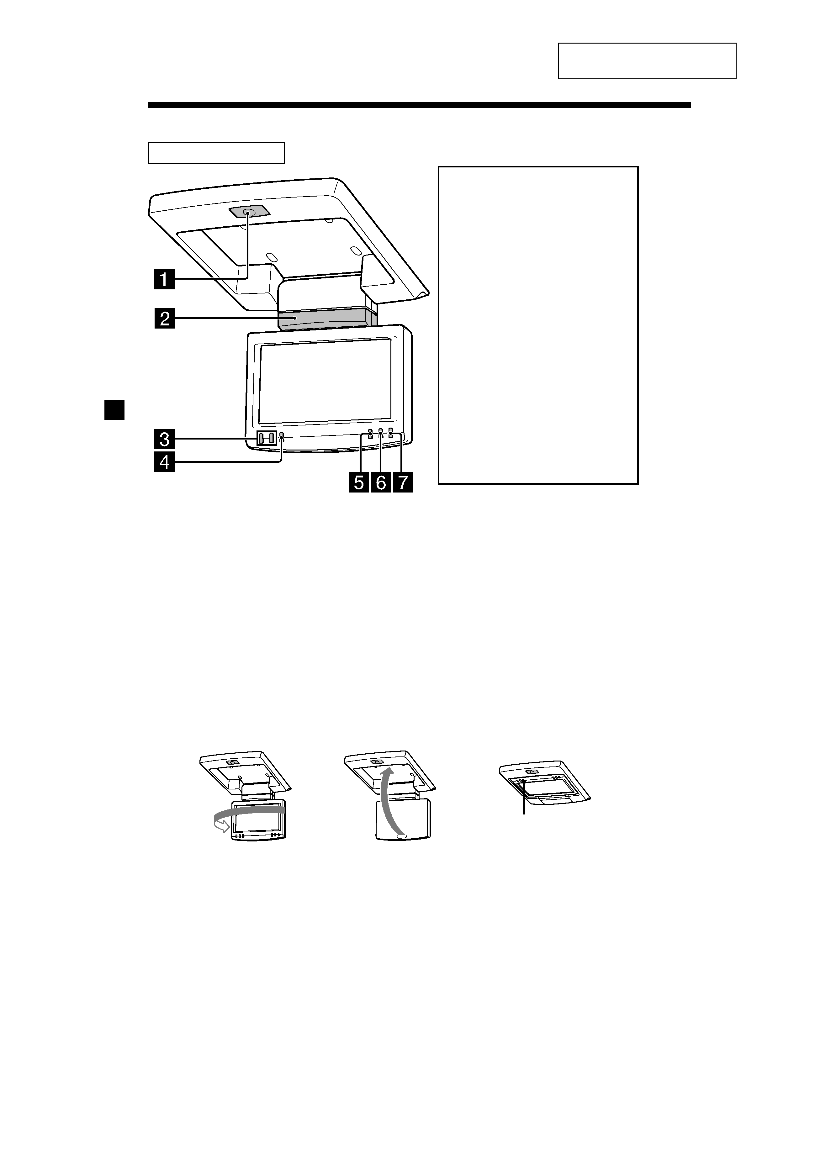
Location of controls
1 OPEN button
To open the monitor.
2 Receptor for the card remote
commander/Transmitter for the
cordless headphones
3 UP/DOWN (
M/m) buttons
To select the desired item.
4 MENU button
To adjust the various display settings.
Monitor XVM-R70
* The reverse position of the display monitor.
You can close with the LCD surface out after turning around 180 degrees, and images on the screen
can be turned upside down by pressing (REVERSE) on the monitor. Before closing the display
monitor, make sure that the monitor is turned and facing the enclosure (you will hear a click). Each
time you press (REVERSE) on the monitor, the reverse screen mode switches between on and off.
5 REVERSE button*
To switch images upside down.
6 INPUT button
To select the input source.
7 POWER button
To turn on/off the player and the
monitor.
REVERSE
180ß
c
c
Warning when installing in a
car without an ACC
(accessory) position on the
ignition key switch
To turn off the player and the
monitor, after you set the power
select switch to B (the setting
without ACC position) for your
car (for details, refer to the installation/
connections manual)
There are 3 ways to turn off the
player and the monitor:
-- After turning off the ignition, be
sure to press (POWER) on the
monitor.
-- After turning off the ignition,
(MONITOR POWER)
on the card
remote commander.
-- After turning off the ignition, just
close the display panel until it
clicks.
Otherwise, the player and the
monitor do not turn off and this
causes battery drain.
SECTION 1
GENERAL
This section is extracted from
instruction manual.
5
MV-7101DS
Ver 1.1
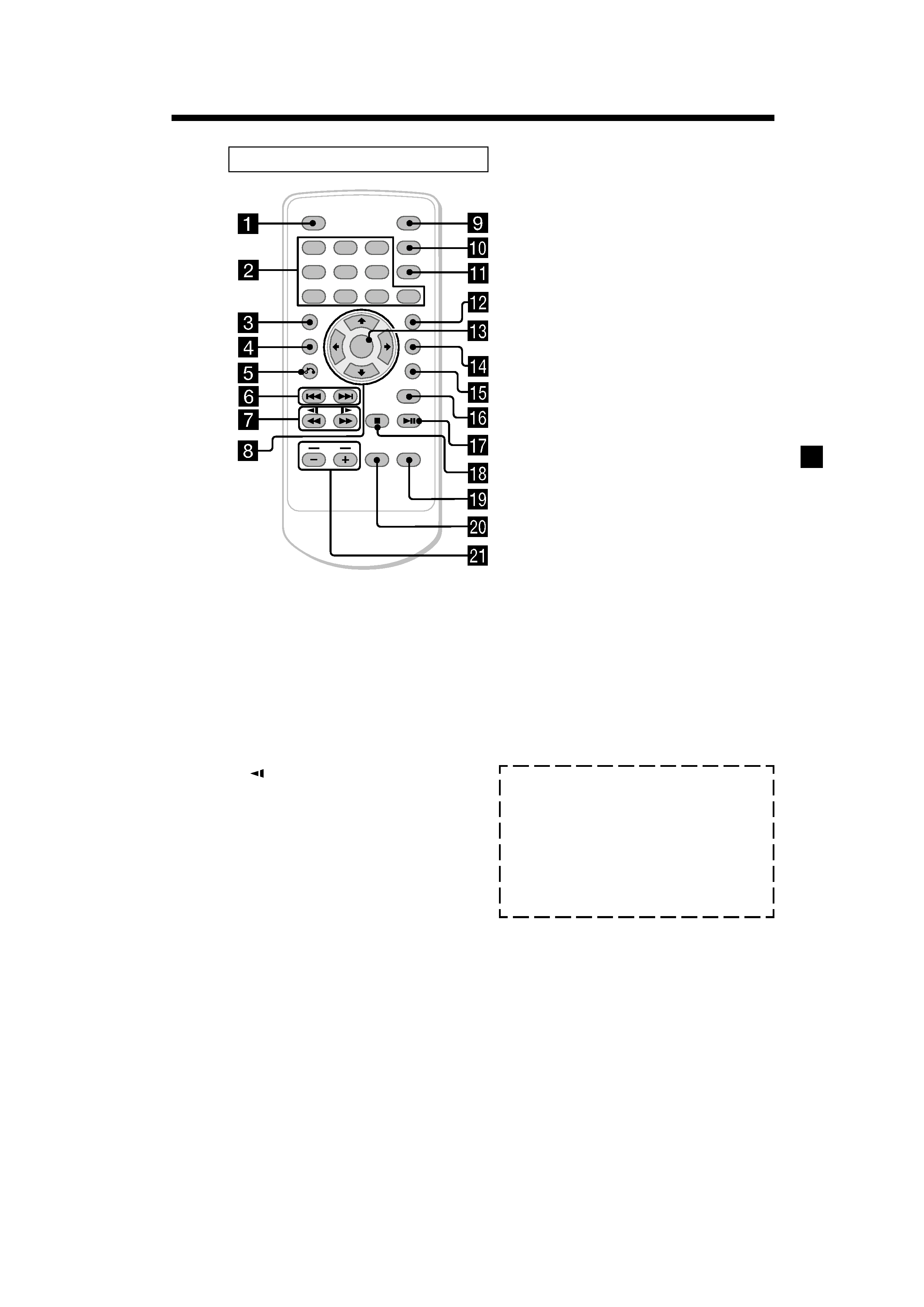
Card remote commander RM-X135
ENTER
SEARCH
POWER
DISPLAY
CLEAR
SETUP
AUDIO
ANGLE
SUBTITLE
MENU
TOP MENU
INPUT
MONITOR
POWER
123
456
7
890
VOL
Refer to the pages listed for details.
1 DISPLAY button
To display a running time.
2 Number buttons
3 TOP MENU button
To display the top menu of a recorded
DVD or to turn on/off the PBC (Playback
control) menu of a Video CD.
4 MENU button
To display the recorded DVD menu.
5 O (return) button
6 ./> (previous/next) buttons
7
/m (fast/slow reverse)/
M
/y (fast/slow forward) buttons
8 M/,/m/< buttons
9 POWER (on/off) button
To turn on/off the player. For details, refer
to the POWER (on/off) button (1) on the
player
q; SEARCH button
To specify a desired point on a disc by
chapter, title, or track.
qa CLEAR button
qs SUBTITLE button
To change the subtitle language while
playing a DVD
qd ENTER button
To enter a setting.
qf ANGLE button
To select the multiple angles of view while
playing or pausing a DVD.
qg AUDIO button
To change the audio output/audio
language
qh SETUP buttons
To enter or quit the setup menu.
qj u (play/pause) button
qk x (stop) button
ql MONITOR POWER (on/off) button*
To turn on/off the player and the monitor.
w; INPUT button*
To select the input source.
wa VOL (/+) buttons*
To turn up or down the volume.
* For the monitor XVM-R70.
These buttons also work for optional Sony
monitors other than XVM-R75 and XVM-H6.
The corresponding buttons of the card
remote commander control the same
functions as those on the player and
the monitor.
Instructions in this manual describe how to use
the player and the monitor by mainly using the
card remote commander.
Tip
Refer to "Replacing the lithium battery of the card
remote commander" for details on how to replace
the battery.
Cautions about the POWER (on/off) button (9)
The POWER (on/off) button (9) is only for the
player. If you want to turn off the player and the
monitor completely, press the MONITOR POWER
(ql).
Cautions about the MONITOR POWER (on/off)
button (ql)
· To turn off the player and the monitor, press the
MONITOR POWER button (ql) or press the
POWER button (7) on the monitor or close the
display panel of the monitor until it clicks.
· To turn on the player and the monitor again, be
sure to press the POWER button (7) on the
monitor.