SERVICE MANUAL
9-873-830-11
Sony Corporation
2001D0500-1
Audio Entertainment Group
C
2001.4
General Engineering Dept.
Ver 1.0 2001.04
MINI HiFi COMPONENT SYSTEM
AEP Model
UK Model
E Model
Australian Model
· MHC-S7AV is composed of following models.
As for the service manual, it is issued for each component model, then, please refer to it.
ACCESSORIES & PACKING MATERIALS
********************************
1-476-530-11 COMMANDER, STANDARD (RM-SR370AV)
1-501-374-11 ANTENNA, LOOP
1-501-659-71 ANTENNA (FM) (AUS, MX)
1-501-721-11 ANTENNA (LOOP)
1-501-804-11 ANTENNA (FM) (AEP, UK, KR)
1-574-264-11 CORD, LIGHT PLUG (OPTICAL)
1-769-306-11 CORD, SPEAKER (1.5m) (for SS-S9)
1-769-433-11 CORD, SPEAKER (10m) (for SS-RS270)
1-769-433-21 CORD, SPEAKER (2.5m) (for SS-CT270)
4-210-254-01 CUSHION (FOOT) (for SS-CT270/RS270)
4-233-737-11 MANUAL, INSTRUCTION (ENGLISH) (AEP, UK, AUS)
4-233-737-21 MANUAL, INSTRUCTION (FRENCH) (AEP)
4-233-737-31 MANUAL, INSTRUCTION (SPANISH) (AEP, MX)
4-233-737-41 MANUAL, INSTRUCTION (GERMAN, DUTCH, ITALIAN)
(AEP)
4-233-737-51 MANUAL, INSTRUCTION (SWEDISH) (AEP)
4-233-737-81 MANUAL, INSTRUCTION (KOREAN) (KR)
4-233-745-11 MANUAL, INSTRUCTION (DANISH, FINNISH) (AEP)
4-233-745-21 MANUAL, INSTRUCTION (PORTUGUESE) (AEP)
4-233-745-31 MANUAL, INSTRUCTION (RUSSIAN) (AEP)
4-233-745-41 MANUAL, INSTRUCTION (GREEK) (AEP)
4-233-745-51 MANUAL, INSTRUCTION (HUNGARIAN, CZECH) (AEP)
4-233-745-61 MANUAL, INSTRUCTION (TURKISH) (AEP)
4-233-745-71 MANUAL, INSTRUCTION (SLOVAKIAN) (AEP)
4-981-643-21 COVER, BATTERY (for RM-SR370AV)
PARTS LIST
Part No.
Description
Remark
MHC-S7AV
HCR-S7AV
·Abbreviation
AUS : Australian model
KR
: Korea model
MX
: Mexican model
SPECIFICATIONS
Power requirements
European model:
230 V AC, 50/60 Hz
Australian model:
230 240 V AC, 50/60 Hz
Mexican model:
120 V AC, 60 Hz
Korean model:
220 V AC, 60 Hz
Other models:
120 V, 220 V or 230 240 V AC, 50/60 Hz
Adjustable with voltage selector
Power consumption
European model:
300 watts
0.6 watts (during Power Saving Mode)
Other models:
300 watts
Dimensions (w/h/d)
TA-S7AV:
Approx. 280
× 128 × 350 mm
ST-S5:
Approx. 280
× 108 × 340 mm
CDP-S3:
Approx. 280
× 108 × 330 mm
TC-S3:
Approx. 280
× 128 × 330 mm
Mass
TA-S7AV:
Approx. 7.7 kg
ST-S5:
Approx. 2.1 kg
CDP-S3:
Approx. 2.7 kg
TC-S3:
Approx. 2.4 kg
Supplied accessories:
AM loop antenna (1)
FM lead antenna (1)
Remote commander (1)
Batteries (2)
Speaker cords (5)
Optical cable (1)
Center and rear speaker pads (12)
Design and specifications are subject to change without notice.
HCR-S7AV is composed of TA-S7AV, CDP-S3, TC-S3, ST-S5, SS-RS270 and SS-CT270.
COMPONENT MODEL NAME FOR MHC-S7AV.
MHC-S7AV
AMPLIFIER
TA-S7AV
CD PLAYER
CDP-S3
TAPE PLAYER
TC-S3
FM STEREO, FM/AM SUPERHETERDYNE TUNER
ST-S5
FRONT SPEAKER
SS-S9
REAR SPEAKER
SS-RS270
CENTER SPEAKER
SS-CT270

2
MHC-S7AV
REVISION HISTORY
Clicking the version allows you to jump to the revised page.
Also, clicking the version at the upper right on the revised page allows you to jump to the next revised
page.
Ver.
Date
Description of Revision
1.0
2001.04
New
SERVICE MANUAL
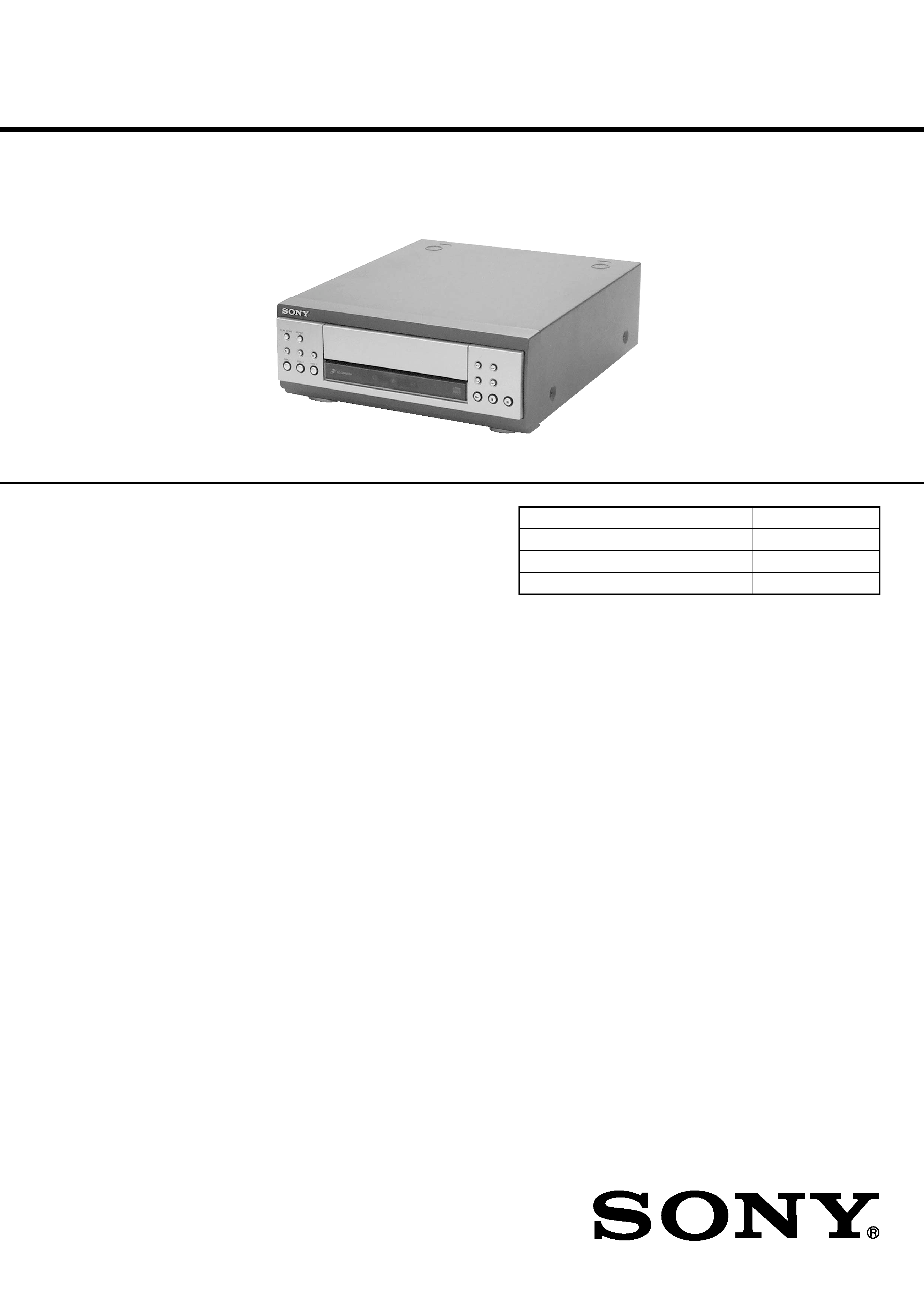
COMPACT DISC PLAYER
AEP Model
UK Model
E Model
Australian Model
SPECIFICATIONS
CDP-S3
Ver 1.0 2001.04
CDP-S3 is the CD player section
in MHC-S7AV or MHC-S3.
Model Name Using Similar Mechanism
NEW
CD Mechanism Type
CDM63B-30BD60
Base Unit Name
BU-30BD60
Optical Pick-up Name
OP Assy (A-MAX.3)
System
Compact disc and digital
audio system
Laser
Semiconductor laser
(
=780 nm)
Emission duration:
continuous
Frequency response
2 Hz 20 kHz (
±0.5 dB)
Signal-to-noise ratio
More than 90 dB
Dynamic range
More than 90 dB
OPTICAL OUT
(Square optical connector jack, rear panel)
Dimensions (w/h/d)
Approx. 280 x 108 x 330 mm
Mass
Approx. 2.7 kg
Design and specifications are subject to change
without notice.
9-873-831-11
Sony Corporation
2001D0500-1
Home Audio Company
C
2001.4
Shinagawa Tec Service Manual Production Group
2
CDP-S3
SAFETY-RELATED COMPONENT WARNING!!
COMPONENTS IDENTIFIED BY MARK 0 OR DOTTED
LINE WITH MARK 0 ON THE SCHEMATIC DIAGRAMS
AND IN THE PARTS LIST ARE CRITICAL TO SAFE
OPERATION. REPLACE THESE COMPONENTS WITH
SONY PARTS WHOSE PART NUMBERS APPEAR AS
SHOWN IN THIS MANUAL OR IN SUPPLEMENTS PUB-
LISHED BY SONY.
The laser diode in the optical pick-up block may suffer electro-
static break-down because of the potential difference generated
by the charged electrostatic load, etc. on clothing and the human
body.
During repair, pay attention to electrostatic break-down and also
use the procedure in the printed matter which is included in the
repair parts.
The flexible board is easily damaged and should be handled with
care.
NOTES ON LASER DIODE EMISSION CHECK
The laser beam on this model is concentrated so as to be focused
on the disc reflective surface by the objective lens in the optical
pick-up block. Therefore, when checking the laser diode emis-
sion, observe from more than 30 cm away from the objective lens.
LASER DIODE AND FOCUS SEARCH OPERATION
CHECK
Carry out the "S curve check" in "CD section adjustment" and
check that the S curve waveforms is output three times.
Notes on chip component replacement
· Never reuse a disconnected chip component.
· Notice that the minus side of a tantalum capacitor may be dam-
aged by heat.
Flexible Circuit Board Repairing
· Keep the temperature of the soldering iron around 270 °C dur-
ing repairing.
· Do not touch the soldering iron on the same conductor of the
circuit board. (within 3 times)
· Be careful not to apply force on the conductor when soldering
or unsoldering.
NOTES ON HANDLING THE OPTICAL PICK-UP
BLOCK OR BASE UNIT
CAUTION
Use of controls or adjustments or performance of procedures
other than those specified herein may result in hazardous ra-
diation exposure.
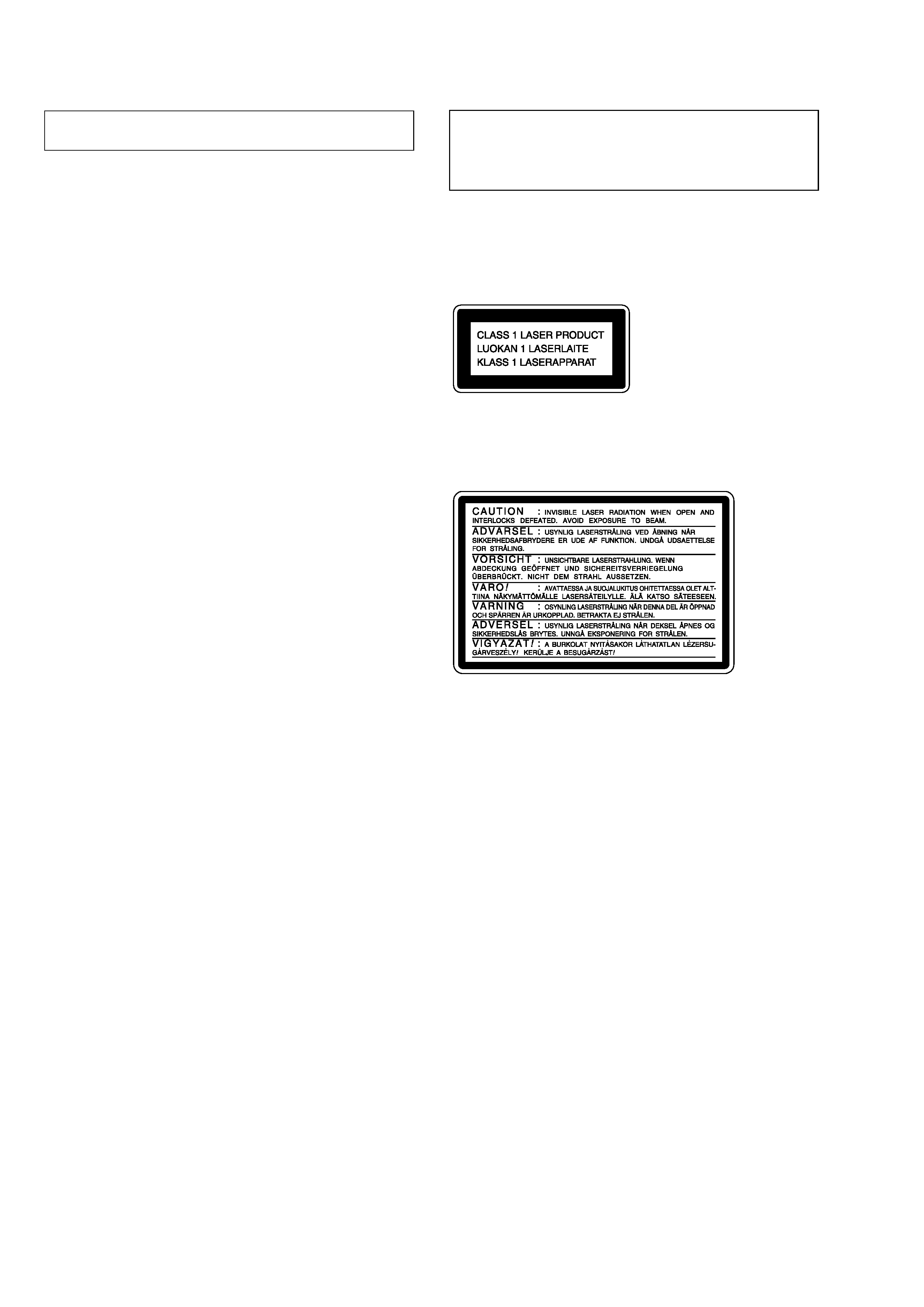
This appliance is classified as a CLASS 1 LASER product.
The CLASS 1 LASER PRODUCT MARKING is located on
the rear exterior.
Laser component in this product is capable of emitting radiation
exceeding the limit for Class 1.
The following caution label is located inside the unit.

3
CDP-S3
TABLE OF CONTENTS
1.
SERVICING NOTES ............................................... 4
2.
GENERAL ................................................................... 5
3.
DISASSEMBLY
3-1. Disassembly Flow ...........................................................
6
3-2. Cover ...............................................................................
7
3-3. CD Mechanism Deck (CDM63B-30BD60) ...................
7
3-4. MAIN Board ...................................................................
8
3-5. Front Panel Section .........................................................
8
3-6. PANEL (L) Board, PANEL (R) Board ...........................
9
3-7. Lid (CD) ..........................................................................
9
4.
TEST MODE .............................................................. 10
5.
ELECTRICAL ADJUSTMENTS ......................... 11
6.
DIAGRAMS
6-1. Note for Printed Wiring Boards
and Schematic Diagrams ................................................ 12
6-2. Printed Wiring Board BD Section ........................... 14
6-3. Schematic Diagram BD Section ............................... 15
6-4. Printed Wiring Boards CD CHANGER Section ..... 16
6-5. Schematic Diagram CD CHANGER Section ......... 17
6-6. Printed Wiring Board MAIN Section ...................... 18
6-7. Schematic Diagram MAIN Section ......................... 19
6-8. Printed Wiring Boards PANEL Section .................. 20
6-9. Schematic Diagram PANEL Section ....................... 21
6-10. IC Pin Function Description ........................................... 24
7.
EXPLODED VIEWS
7-1. General Section ............................................................... 26
7-2. CD Mechanism Deck Section-1
(CDM63B-30BD60) ....................................................... 27
7-3. CD Mechanism Deck Section-2
(CDM63B-30BD60) ....................................................... 28
7-4. Base Unit Section (BU-30BD60) ................................... 29
8.
ELECTRICAL PARTS LIST ............................... 30