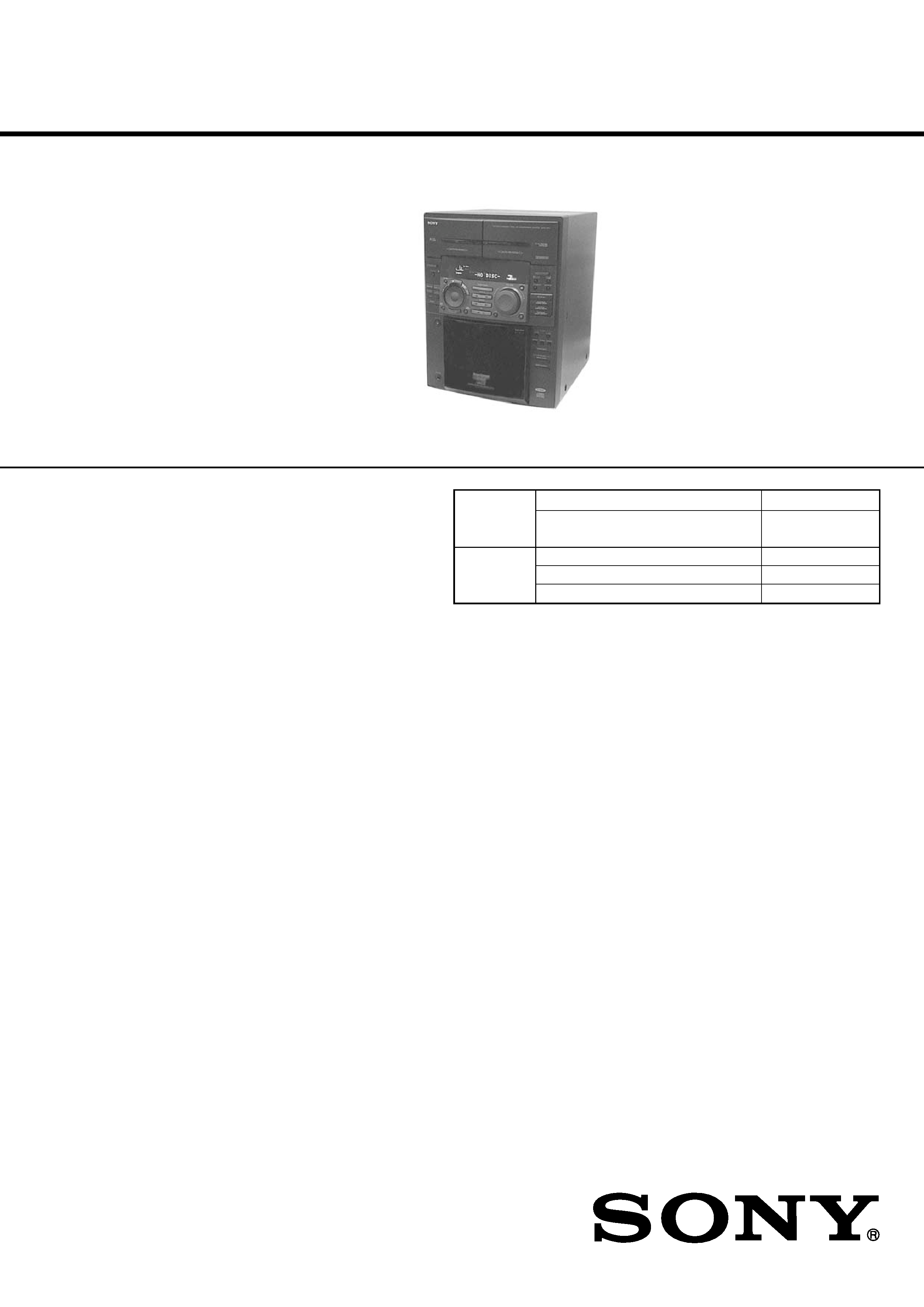
SERVICE MANUAL
MINI HI-FI COMPONENT SYSTEM
HCD-F50/F100/FR1
US Model
Canadian Model
HCD-F50/F100
AEP Model
UK Model
E Model
Australian Model
HCD-FR1
HCD-F50/F100/FR1 is the tuner, deck,
CD and amplifier section in MHC-F50/
F100/FR1.
*
Dolby noise reduction manufacrured
under license from Dolby Laboratories
Licensing corporation.
"DOLBY" and the double-D symbol ;
are trademarks of Dolby Laboratories
Licensing Corporation.
Photo: HCD-FR1
SPECIFICATIONS
CD player section
System
Compact disc and digital audio
system
Laser
Semiconductor laser
(
=780nm)
Emission duration: continuous
Laser output
Max. 44.6
µW*
*This output is the value mea-
sured at a distance of 200 mm
from the objective lens surface
-on the Optical Pick-up Block
with 7 mm aperture.
Wavelength
780-790 nm
CD OPTICAL DIGITAL OUT
(Square optical connector jack, rear panel)
Wavelength
600 nm
Inputs
VIDEO/MD IN (phono jacks) :
voltage 250 mV,impedance 47
kilohms
MIX MIC (phone jack)
(Singapore model):
sensitivity 1 mV,
impedance 10 kilohms
Outputs
VIDEO/MD OUT (phono jacks)
: voltage 250 mV impedance
1 kilohms
PHONES (stereo phone jack) :
accepts headphones of 8 ohms or
more.
SPEAKER : accepts impedance of
8 to 16 ohms (F100/FR1)
accepts impedance of 6 to 16 ohms
(F50)
SURROUND SPEAKER
(F100/FR1):
accepts impedance of 16 ohms.
SUPER WOOFER (F100/FR1):
Voltage 1 V, impedance 1 kilo ohm
For the US model
AUDIO POWER SPECIFICATIONS
POWER OUTPUT AND TOTAL
HARMONIC DISTORTION:
With 8 ohm loads, both channels driven, from
70-20,000 Hz; rated 100 watts per channel
minimum RMS power, with no more than
0.9% total harmonic distortion from 250
milliwatts to rated output.
Amplifier section
Continuous RMS power output
Canadian model
100+100 watts
(8 ohms at 1 kHz, 5% THD)
(F100)
60+60 watts
(6 ohms at 1 kHz, 5% THD)
(F50)
Other models
100+100 watts
(8 ohm at 1 kHz, 10% THD)
Peak music power output (EXCEPT US, Canadian) :
1400 watts
Continued on next page
Model Name Using Similar Mechanism
NEW
CD Mechanism Type
CDM-46B1 (F100/FR1)
CDM-46B2 (F50)
Optical Pick-up Name
KSS-213B/S-N
Model Name Using Similar Mechanism
HCD-D690/XB6
Tape Transport Mechanism Type
TCM-220WR2
CD
Section
Tape deck
Section
9-960-949-12
2005B05-1
© 2005.02
Sony Corporation
Audio Group
Published by Sony Engineering Corporation
Ver. 1.1 2005.02
2
Tape player section
Recording system
4-track 2-channel stereo
Frequency response
60 - 13,000 Hz (±3 dB), using Sony TYPE I cassette
(DOLBY NR OFF)
60 - 14,000 Hz (±3 dB), using Sony TYPE II cassette
Tuner section
FM stereo, FM/AM superheterodyne tuner
FM tuner section
Tuning range
87.5 - 108,0 MHz
Antenna terminals
75 ohm unbalanced
Intermediate frequency 10.7 MHz
AM tuner section
Tuning range
North American model:
530 - 1,710 kHz
(with the AM tuning interval set at 10kHz)
531 - 1,710 kHz
(with the AM tuning interval set at 9 kHz)
Singaporian model:
MW 531 - 1,602 kHz
(with the MW tuning interval set at 9 kHz)
530 - 1,710 kHz
(with the MW tuning interval set at 10 kHz)
SW 5.95 - 17.90 MHz
(with the SW tuning interval set at 5 kHz)
Other models:
531 - 1,602 kHz
(with the AM tuning interval set at 9 kHz)
530 - 1,710 kHz
(with the AM tuning interval set at 10 kHz)
Intermediate frequency 450 kHz
Antenna
AM loop antenna
External antenna terminal
General
Power requirements
North American model: 120 V AC, 60 Hz
Australian model:
220 - 240 V AC, 50/60 Hz
AEP, UK, G models:
220 - 230V AC, 50/60 Hz
Other models:
110 - 120 V or 220 - 240 V AC,
50/60 Hz Adjustable with voltage selector
Power consumption
U.S. model:
195 watts (HCD-F100)
110 watts (HCD-F50)
Canadian model:
195 watts (HCD-F100)
120 watts (HCD-F50)
Other models:
210 watts
Dimensions (w/h/d)
Approx. 280
×375×450 mm
Mass
Approx. 11.5 kg (HCD-F100/FR1)
Approx. 10 kg (HCD-F50)
Supplied accessories:
AM loop antena (1)
Remote RM-SF100 (1) (F100/FR1)
Remote RM-SF50 (1) (F50)
Sony SUM-3 (N5)
batteries (2)
FM lead antenna (1)
Speaker coreds (2)
Design and specifications are subject to change without notice.
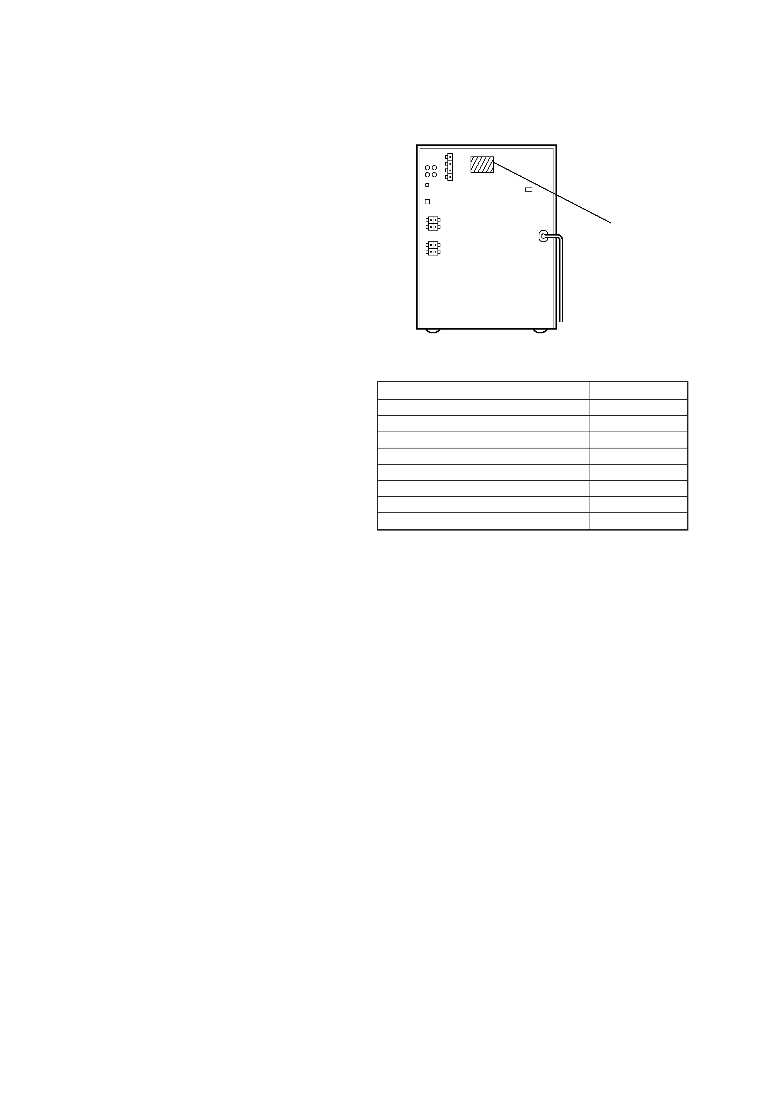
MEDEL IDENTIFICATION
BACK PANEL
MODEL
PARTS NO.
F50 : US model
4-990-400-0
F50 : Canadeian model
4-990-400-1
F100 : US model
4-990-364-0
F100 : Canadian model
4-990-364-1
FR1 : AEP, UK, German model
4-990-364-2
FR1 : E model
4-990-364-5
FR1 : Australian model
4-990-364-6
FR1 : Singapore model
4-990-364-9
PARTS No.
3
CAUTION
Use of controls or adjustments or performance of
procedures other than those specified herein may
result in hazardous radiation exposure.
This appliance is classified as a CLASS 1 LASER product.
The CLASS 1 LASER PRODUCT MARKING is located on
the rear exterior.
SAFETY CHECK-OUT
After correcting the original service problem, perform the follow-
ing safety check before releasing the set to the customer:
Check the antenna terminals, metal trim, "metallized" knobs,
screws, and all other exposed metal parts for AC leakage.
Check leakage as described below.
LEAKAGE TEST
The AC leakage from any exposed metal part to earth ground and
from all exposed metal parts to any exposed metal part having a
return to chassis, must not exceed 0.5 mA (500 microampers.).
Leakage current can be measured by any one of three methods.
1. A commercial leakage tester, such as the Simpson 229 or RCA
WT-540A. Follow the manufacturers' instructions to use these
instruments.
2. A battery-operated AC milliammeter. The Data Precision 245
digital multimeter is suitable for this job.
3. Measuring the voltage drop across a resistor by means of a
VOM or battery-operated AC voltmeter. The "limit" indica-
tion is 0.75 V, so analog meters must have an accurate low-
voltage scale. The Simpson 250 and Sanwa SH-63Trd are ex-
amples of a passive VOM that is suitable. Nearly all battery
operated digital multimeters that have a 2 V AC range are suit-
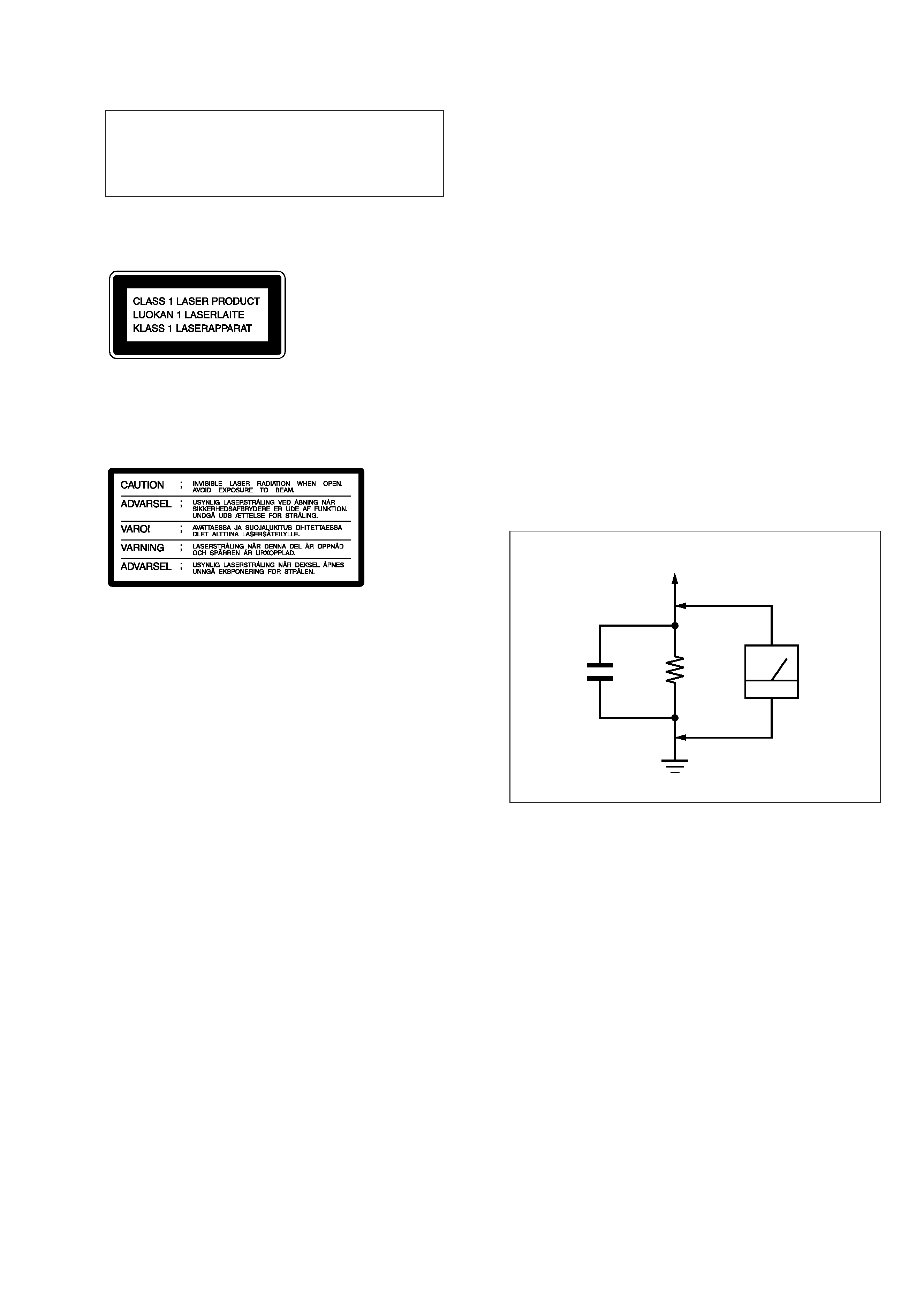
able. (See Fig. A)
Fig. A.
Using an AC voltmeter to check AC leakage.
1.5 k
0.15
µF
AC
voltmeter
(0.75 V)
To Exposed Metal
Parts on Set
Earth Ground
ATTENTION AU COMPOSANT AYANT RAPPORT
À LA SÉCURITÉ!
LES COMPOSANTS IDENTIFIÉS PAR UNE MARQUE
!
SUR LES DIAGRAMMES SCHÉMATIQUES ET LA LISTE
DES PIÈCES SONT CRITIQUES POUR LA SÉCURITÉ
DE FONCTIONNEMENT. NE REMPLACER CES COM-
POSANTS QUE PAR DES PIÈCES SONY DONT LES
NUMÉROS SONT DONNÉS DANS CE MANUEL OU
DANS LES SUPPLÉMENTS PUBLIÉS PAR SONY.
SAFETY-RELATED COMPONENT WARNING!!
COMPONENTS IDENTIFIED BY MARK
! OR DOTTED
LINE WITH MARK
! ON THE SCHEMATIC DIAGRAMS
AND IN THE PARTS LIST ARE CRITICAL TO SAFE
OPERATION. REPLACE THESE COMPONENTS WITH
SONY PARTS WHOSE PART NUMBERS APPEAR AS
SHOWN IN THIS MANUAL OR IN SUPPLEMENTS PUB-
LISHED BY SONY.
Laser component in this product is capable of emitting radiation
exceeding the limit for Class 1.
The following caution label is located inside the unit.