SERVICE MANUAL
AUDIO LIBRARY SYSTEM
SPECIFICATIONS
MEX-1HD
Model Name Using Similar Mechanism
NEW
CD Drive Mechanism Type
MG-550D-156
Optical Block Name
CDM-3021EBG
Optical Pick-up Name
DAX-21EG
US Model
Canadian Model
E Model
Australian Model
Ver 1.3 2004.02
9-873-923-04
Sony Corporation
2004B05-1
e Vehicle Company
© 2004.02
Published by Sony Engineering Corporation
CD Player section
Signal-to-noise ratio
90 dB
Frequency response
10 20,000 Hz
"MG Memory Stick" section
Signal-to-noise ratio
90 dB
Frequency response
10 20,000 Hz
Recording time (when using the supplied 64MB
"MagicGate Memory Stick")
Approx. 60 min. (132kbps)
Approx. 80 min. (105kbps)
Recording format
Adaptive Transform
Acoustic Coding 3
(ATRAC3)
HDD section
Capacity
10 GB
Recording format
Adaptive Transform
Acoustic Coding 3
(ATRAC3)
Frequency response
20 to 20,000 Hz
(single signal measurement)
Tuner section
FM
Tuning range
87.5 107.9 MHz
Antenna terminal
External antenna connector
Intermediate frequency
10.7 MHz/450 kHz
Usable sensitivity
8 dBf
Selectivity
75 dB at 400 kHz
Signal-to-noise ratio
66 dB (stereo),
72 dB (mono)
Harmonic distortion at 1 kHz
0.6 % (stereo),
0.3 % (mono)
Separation
35 dB at 1 kHz
Frequency response
30 15,000 Hz
AM
Tuning range
530 1,710 kHz
Antenna terminal
External antenna connector
Intermediate frequency
10.7 MHz/450 kHz
Sensitivity
30
µV
Power amplifier section
Outputs
Speaker outputs
(sure seal connectors)
Speaker impedance
4 8 ohms
Maximum power output
52 W
× 4 (at 4 ohms)
General
Outputs
Audio outputs (front/rear)
Subwoofer output (mono)
Power antenna relay control
terminal
Power amplifier control
terminal
Inputs
Telephone ATT control
terminal
Illumination control
terminal
AUX IN terminal
Antenna input terminal
Tone controls
Bass
±8 dB at 100 Hz
Treble
±8 dB at 10 kHz
Loudness
+8 dB at 100 Hz
+2 dB at 10 kHz
Power requirements
12 V DC car battery
(negative ground)
Dimensions
Approx. 178
× 50 × 182 mm
(7 1/8
× 2 × 7 1/4 in.)
(w/h/d)
Mounting dimensions
Approx. 182
× 53 × 161 mm
(7 1/4
× 2 1/8 × 6 3/8 in.)
(w/h/d)
Mass
Approx. 2.0 kg
(4 lb. 7 oz.)
Supplied accessories
Parts for installation and
connections (1 set)
Front panel case (1)
Cleaning cloth (1)
Digital I/O cable (1)
Note
This unit cannot be connected to a digital preamplifier
or an equalizer.
Design and specifications are subject to change
without notice.
POWER OUTPUT AND TOTAL HARMONIC DISTORTION
23 watts per channel minimum continuous average power into 4 ohms,
4 channels driven from 20 Hz to 20 kHz with no more than 5% total
harmonic distortion.
AUDIO POWER SPECIFICATIONS
(US model only)

2
MEX-1HD
1.
SERVICING NOTES ................................................ 5
2.
GENERAL
Location of Controls .......................................................
7
3.
DISASSEMBLY
3-1. Disassembly Flow ........................................................... 10
3-2. Cover ............................................................................... 11
3-3. Base Panel Assy .............................................................. 11
3-4. Sub Panel (CD) Assy ...................................................... 12
3-5. Mechanism Deck (MG-550D-156) ................................ 12
3-6. Motor Block Assy, Cam Block Assy .............................. 13
3-7. Motor Assy (Front Panel Open/Close) (M601),
SWITCH Board ............................................................... 13
3-8. MAIN Board, POWER Board ........................................ 14
3-9. Hard Disk Drive (2.5 inch) Unit ..................................... 15
3-10. SUB Board ...................................................................... 15
3-11. Heat Sink, DC Fan (M501) ............................................. 16
3-12. Belt (L), LE Motor Assy (Tray Open/Close) (M103) .... 16
3-13. Tray (UD) Assy ............................................................... 17
3-14. OP Assy (CDM-3021EBG) ............................................ 17
3-15. SERVO Board ................................................................. 18
4.
ASSEMBLY
4-1. Assembly Flow ................................................................ 19
4-2. Motor Block Assy ........................................................... 19
4-3. Cam Block Assy .............................................................. 20
4-4. Phase Alignment of Motor Block Assy and
Cam Block Assy .............................................................. 20
5.
TEST MODE .............................................................. 21
6.
DIAGRAMS
6-1. Block Diagram
SERVO, HD/MS/USB INTERFACE Section .......... 27
6-2. Block Diagram CPU, DISPLAY Section ................ 28
6-3. Block Diagram AUDIO, SYSTEM Section ............ 29
6-4. Block Diagram POWER SUPPLY Section ............. 30
6-5. Note for Printed Wiring Boards and
Schematic Diagrams ....................................................... 31
6-6. Printed Wiring Board SERVO Board (Side A) ....... 32
6-7. Printed Wiring Board SERVO Board (Side B) ....... 33
6-8. Schematic Diagram SERVO Board (1/3) ................ 34
6-9. Schematic Diagram SERVO Board (2/3) ................ 35
6-10. Schematic Diagram SERVO Board (3/3) ................ 36
6-11. Printed Wiring Board MAIN Board (Side A) ......... 38
6-12. Printed Wiring Board MAIN Board (Side B) ......... 39
6-13. Schematic Diagram MAIN Board (1/9) ................... 40
6-14. Schematic Diagram MAIN Board (2/9) ................... 41
6-15. Schematic Diagram MAIN Board (3/9) ................... 42
6-16. Schematic Diagram MAIN Board (4/9) ................... 43
6-17. Schematic Diagram MAIN Board (5/9) ................... 44
6-18. Schematic Diagram MAIN Board (6/9) ................... 45
6-19. Schematic Diagram MAIN Board (7/9) ................... 46
6-20. Schematic Diagram MAIN Board (8/9) ................... 47
6-21. Schematic Diagram MAIN Board (9/9) ................... 48
6-22. Schematic Diagram SUB Board (1/5) ...................... 49
6-23. Schematic Diagram SUB (2/5)/SWITCH Boards .... 50
6-24. Schematic Diagram SUB Board (3/5) ...................... 51
6-25. Schematic Diagram SUB Board (4/5) ...................... 52
6-26. Schematic Diagram SUB Board (5/5) ...................... 53
6-27. Printed Wiring Boards
SUB (Component Side)/Switch Boards ................... 54
6-28. Printed Wiring Board
SUB Board (Conductor Side) ................................... 55
6-29. Printed Wiring Board POWER Board ..................... 56
6-30. Schematic Diagram POWER Board ........................ 57
6-31. Printed Wiring Board DISPLAY Board .................. 58
6-32. Schematic Diagram DISPLAY Board ..................... 59
6-33. IC Pin Function Description ........................................... 69
7.
EXPLODED VIEWS
7-1. Cover Section ................................................................. 97
7-2. Front Panel Section ........................................................ 98
7-3. ARM Section .................................................................. 99
7-4. Hard Disk, POWER Board Section ............................... 100
7-5. MAIN Board Section ..................................................... 101
7-6. Chassis Section .............................................................. 102
7-7. SUB Board Section ........................................................ 103
7-8. Mechanism Deck Section (MG-550D-156) .................. 104
8.
ELECTRICAL PARTS LIST .............................. 106
TABLE OF CONTENTS
Ver 1.1
3
MEX-1HD
SAFETY-RELATED COMPONENT WARNING!!
COMPONENTS IDENTIFIED BY MARK 0 OR DOTTED
LINE WITH MARK 0 ON THE SCHEMATIC DIAGRAMS
AND IN THE PARTS LIST ARE CRITICAL TO SAFE
OPERATION. REPLACE THESE COMPONENTS WITH
SONY PARTS WHOSE PART NUMBERS APPEAR AS
SHOWN IN THIS MANUAL OR IN SUPPLEMENTS PUB-
LISHED BY SONY.
Notes on chip component replacement
·Never reuse a disconnected chip component.
· Notice that the minus side of a tantalum capacitor may be dam-
aged by heat.
Flexible Circuit Board Repairing
·Keep the temperature of the soldering iron around 270 °C dur-
ing repairing.
· Do not touch the soldering iron on the same conductor of the
circuit board (within 3 times).
· Be careful not to apply force on the conductor when soldering
or unsoldering.
CAUTION
Use of controls or adjustments or performance of procedures
other than those specified herein may result in hazardous ra-
diation exposure.
ATTENTION AU COMPOSANT AYANT RAPPORT
À LA SÉCURITÉ!
LES COMPOSANTS IDENTIFIÉS PAR UNE MARQUE 0
SUR LES DIAGRAMMES SCHÉMATIQUES ET LA LISTE
DES PIÈCES SONT CRITIQUES POUR LA SÉCURITÉ
DE FONCTIONNEMENT. NE REMPLACER CES COM-
POSANTS QUE PAR DES PIÈCES SONY DONT LES
NUMÉROS SONT DONNÉS DANS CE MANUEL OU
DANS LES SUPPLÉMENTS PUBLIÉS PAR SONY.
·The recorded music is limited to private use only.
Use of the music beyond this limit requires
permission of the copyright holders.
·Sony is not responsible for music files that are not
saved on this unit due to unsuccessful recording
from CD or music downloading.
·Sony is not responsible for any files that are
damaged or erased from the hard disc.
Notes
Notes on CD-Rs (recordable CDs)/CD-
RWs (rewritable CDs)
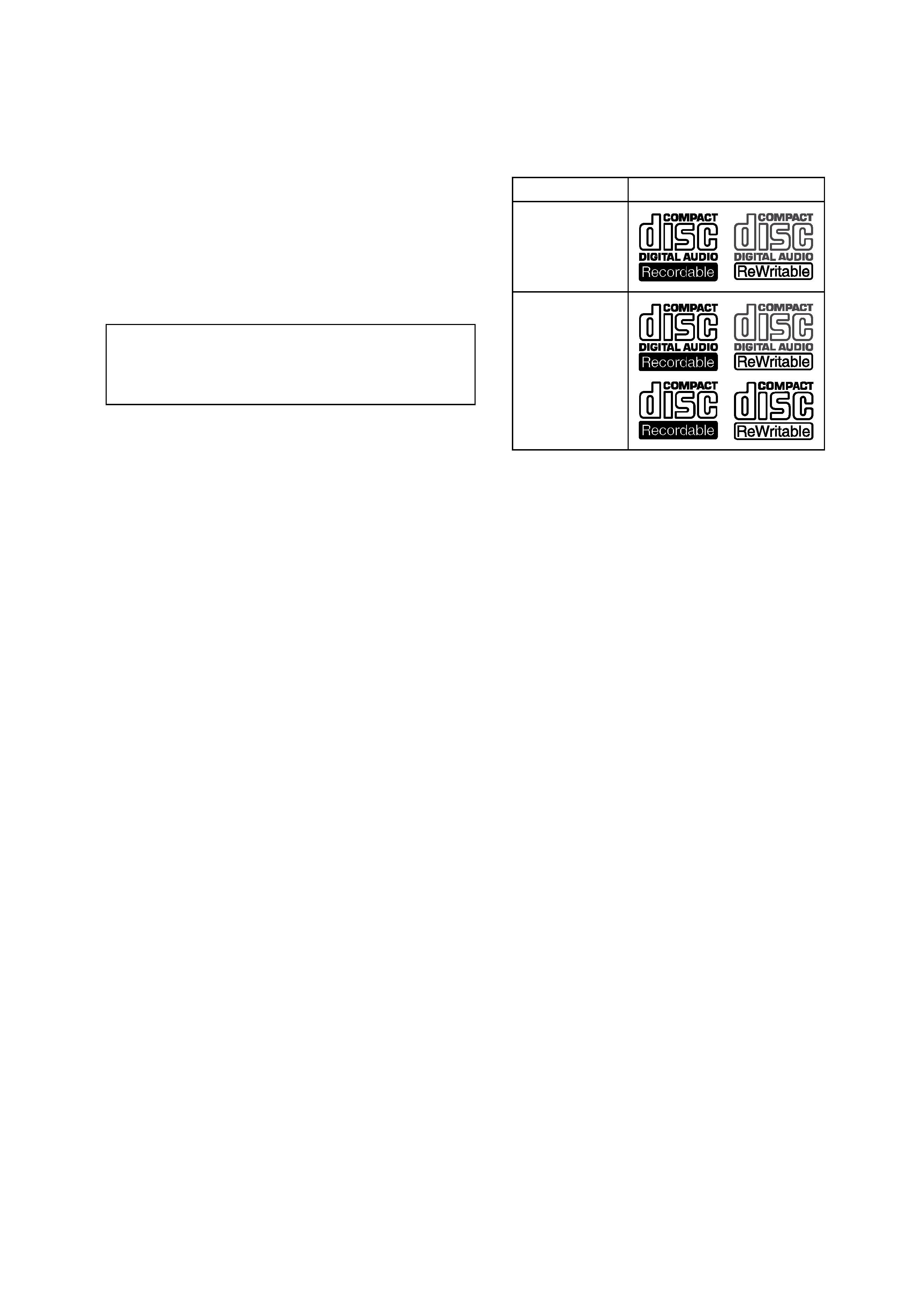
This unit can play the following discs:
·Some CD-Rs/CD-RWs (depending on the
equipment used for its recording or the
condition of the disc) may not play on this unit.
·You cannot play a CD-R/CD-RW that is not
finalized*.
·You can play MP3 files recorded on CD-
ROMs, CD-Rs, and CD-RWs.
·A CD-R/CD-RW to which a session can be
added can be played.
* A process necessary for a recorded CD-R/CD-RW
disc to be played on the audio CD player.
Type of discs
Label on the disc
Audio CD
MP3 files

4
MEX-1HD
Notes on MP3 files
MP3 (MPEG 1 Audio Layer-3) is a standard
technology and format for compressing a sound
sequence. The file is compressed to about 1/10 of
its original size. Sounds outside the range of
human hearing are compressed while the sounds
we can hear are not compressed.
Notes on discs
You can play MP3 files recorded on CD-ROMs,
CD-Rs, and CD-RWs.
The disc must be in the ISO 9660*1 level 1 or
level 2 format, or Joliet or Romeo in the
expansion format.
You can use a disc recorded in Multi Session*2.
*1
ISO 9660 Format
The most common international standard for
the logical format of files and folders on a
CD-ROM.
There are several specification levels. In
Level 1, file names must be in the 8.3 format
(no more than 8 characters in the name, no
more than 3 characters in the extension
".MP3") and in capital letters. Folder names
can be no longer than 8 characters. There can
be no more than 8 nested folder levels. Level
2 specifications allow file names up to 31
characters long.
Each folder can have up to 8 trees.
For Joliet or Romeo in the expansion format,
make sure of the contents of the writing
software, etc.
*2
Multi Session
This is a recording method that enables
adding of data using the Track-At-Once
method. Conventional CDs begin at a CD
control area called the Lead-in and end at an
area called Lead-out. A Multi Session CD is a
CD having multiple sessions, with each
segment from Lead-in to Lead-out regarded
as a single session.
CD-Extra: The format which records audio
(audio CD data) as tracks on session 1, and
records data as tracks on session 2.
Mixed CD: In this format, data is recorded as
track, and audio (audio CD data) is recorded
as track 2.
Notes
· With formats other than ISO 9660 level 1 and level 2,
folder names or file names may not be displayed
correctly.
· When naming, be sure to add the file extension
".MP3" to the file name.
· If you put the extension ".MP3" to a file other than
MP3, the unit cannot recognize the file properly and
will generate random noise that could damage your
speakers.
· The following discs take a longer time to start
playback.
a disc recorded with a complicated tree structure.
a disc recorded in Multi Session.
a disc to which data can be added.
Cautions when playing a disc that is recorded in
Multi Session
· When the first track of the first session is audio CD
data:
Only audio CD data is played back.
· When the first track of the first session is not audio
CD data:
If an MP3 file is in the disc, only MP3 file(s) play
back and other data is skipped. (Audio CD data is
not recognized.)
If no MP3 file is in the disc, "NO Music" is
displayed and nothing is played back. (Audio CD
data is not recognized.)
5
MEX-1HD
SECTION 1
SERVICING NOTES
NOTES ON HANDLING THE OPTICAL PICK-
UP BLOCK OR BASE UNIT
The laser diode in the optical pick-up block may suffer electro-
static breakdown because of the potential difference generated by
the charged electrostatic load, etc. on clothing and the human body.
During repair, pay attention to electrostatic breakdown and also
use the procedure in the printed matter which is included in the
repair parts.
The flexible board is easily damaged and should be handled with
care.
NOTES ON LASER DIODE EMISSION CHECK
The laser beam on this model is concentrated so as to be focused
on the disc reflective surface by the objective lens in the optical
pick-up block. Therefore, when checking the laser diode emis-
sion, observe from more than 30 cm away from the objective lens.
Laser Diode Properties
· Material: GaAlAs
·Wavelength: 780 nm
· Emission Duration: continuous
· Laser Output Power: less than 44.6
µW*
*This output is the value measured at a distance of 200 mm
from the objective lens surface on the Optical Pick-up Block.
Ver 1.1
CHECKING THE VERSION BEFORE REPLACEMENT OF
FLASH MEMORY (IC1030 ON MAIN BOARD)
This set is available with two types, Initial Lot type and User Up-
grade type, depending on the software version used in the micro-
computer.
If the Flash Memory (IC1030 on MAIN board) or mounted MAIN
board was replaced, the work (*1) required after parts replace-
ment is different according to the type. Therefore, before parts
replacement, check the type of set, and then perform the work
(*1) necessary for that type. However, if the version check is im-
possible because of a trouble in the set, handle it as a User Up-
grade type.
*1: For the work required after parts replacement, refer to "Setup
After Parts Replacement" and "Version Up After Microcom-
puter Software Related Parts Replacement" (page 22) in the
following section.
Procedure for check the version:
1. Select the "Test Mode" from the test mode main menu by ro-
tating the right jog dial (PUSH LIST), and press the right jog
button (PUSH LIST) to enter the Test Mode.
2. Rotate the right jog dial (PUSH LIST) to select the "Version",
and press the right jog button (PUSH LIST) to enter the Ver-
sion mode.
3. With the "Version" mode activated, press the right jog button
(PUSH LIST), and the versions of Main, Sub, CD Servo will
be displayed respectively. Check the version of "Main".
Version by type:
Initial Lot type
: 1.00.05
User Upgrade type : 2.03.02
SETUP AFTER PARTS REPLACEMENT
This set requires the work such as microcomputer software ver-
sion up, system ID setting and HDD formatting, if either of flash
memory, microcomputer (or mounted MAIN, SUB, or SERVO
board) and hard disk drive (HDD) was replaced.
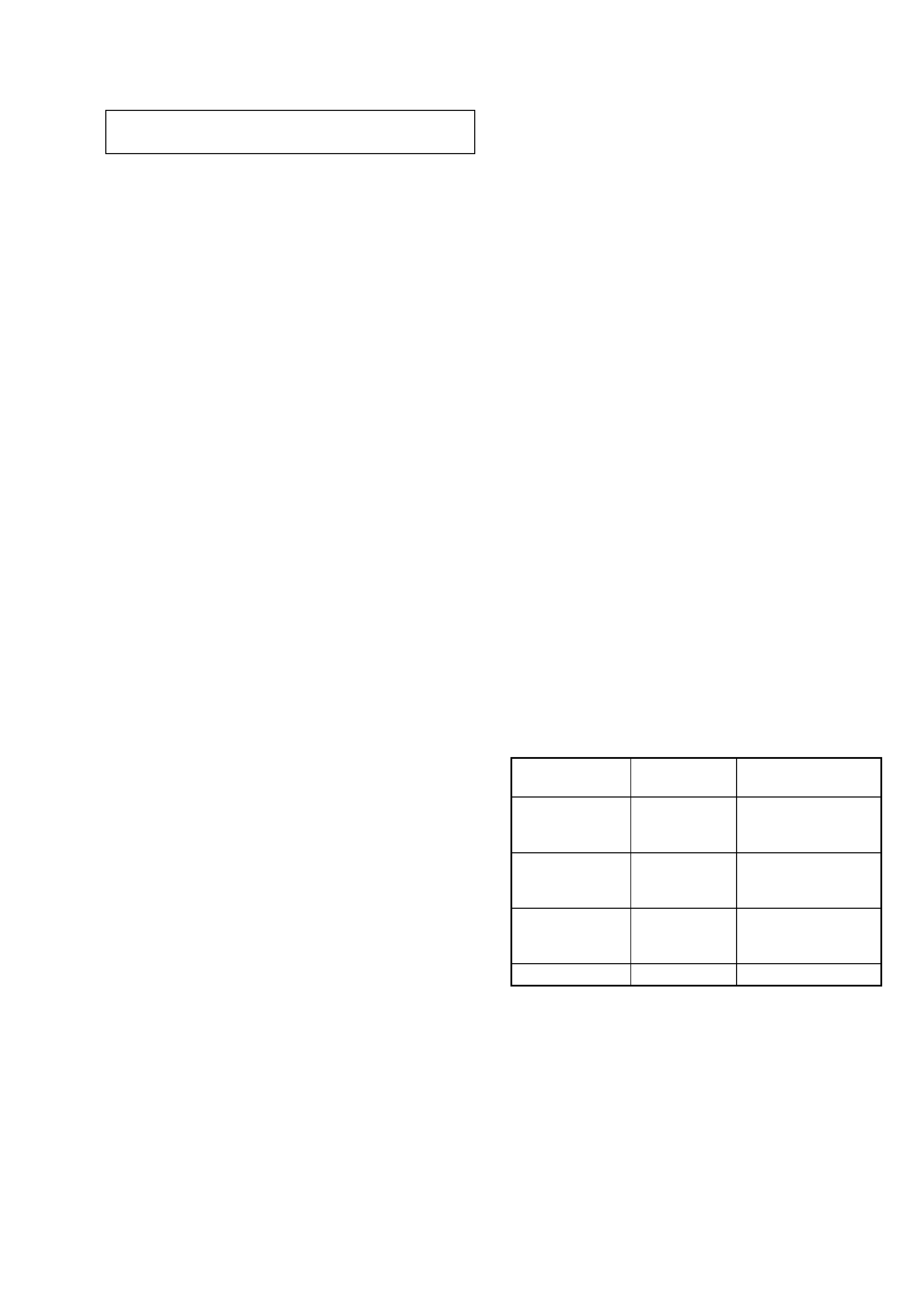
Perform the work required by referring to the "Test mode", if ei-
ther of the following parts was replaced.
Replacement
Version up
System ID setting
parts
and HDD processing
Flash memory
(IC1030 on MAIN
aa
board) *1
Microcomputer
(IC501 on SUB
a
board) *1
Flash memory
(IC9 on SERVO
a
board) *1
HDD
a *2
*1: Including the case where the mounted board as a whole is re-
placed.
*2: Executing the HDD formatting causes the user's recorded data
to be all erased, and therefore be careful not to execute this
operation by mistake if the HDD was not replaced.
Version up:
Refer to "Version Up After Microcomputer Software Related
Parts Replacement".
System ID setting and HDD processing:
Refer to "Relating with ID".