SERVICE MANUAL
FM/MW/LW MINI DISC PLAYER
AEP Model
UK Model
SPECIFICATIONS
MDX-M690
Ver 1.0 2001.03
9-870-294-11
Sony Corporation
2001C0500-1
Audio Entertainment Group
C
2001.3
General Engineering Dept.
US and foreign patents licensed from Dolby Laboratories.
Model Name Using Similar Mechanism
MDX-CA680
Base Mechanism Type
MG-164MA-138
Optical Pick-up Name
KMS-241C
MD Player section
Signal-to-noise ratio
90 dB
Frequency response
10 20,000 Hz
Wow and flutter
Below measurable limit
Tuner section
FM
Tuning range
87.5 108.0 MHz
Aerial terminal
External aerial connector
Intermediate frequency
10.7 MHz/450 kHz
Usable sensitivity
8 dBf
Selectivity
75 dB at 400 kHz
Signal-to-noise ratio
66 dB (stereo),
72 dB (mono)
Harmonic distortion at 1 kHz
0.6 % (stereo),
0.3 % (mono)
Separation
35 dB at 1 kHz
Frequency response
30 15,000 Hz
MW/LW
Tuning range
MW: 531 1,602 kHz
LW: 153 279 kHz
Aerial terminal
External aerial connector
Intermediate frequency
10.7 MHz/450 kHz
Sensitivity
MW: 30
µV
LW: 40
µV
Power amplifier section
Outputs
Speaker outputs
(sure seal connectors)
Speaker impedance
4 8 ohms
Maximum power output
52 W
× 4 (at 4 ohms)
General
Outputs
Audio outputs (front/rear)
Subwoofer output (mono)
Power aerial relay control
lead
Power amplifier control lead
Inputs
Telephone ATT control lead
Illumination control lead
BUS control input
connector
BUS audio input connector
Remote controller input
connector
Aerial input connector
Loudness
+8 dB at 100 Hz
+2 dB at 10 kHz
Power requirements
12 V DC car battery
(negative earth)
Dimensions
Approx. 178
× 50 × 182 mm
(w/h/d)
Mounting dimensions
Approx. 182
× 53 × 160 mm
(w/h/d)
Mass
Approx. 1.5 kg
Supplied accessories
Parts for installation and
connections (1 set)
Front panel case (1)
Card remote commander
RM-X111
Tone controls
Bass
±8 dB at 100 Hz
Treble
±8 dB at 10 kHz
Note
This unit cannot be connected to a digital preamplifier
or an equalizer.
Design and specifications are subject to change
without notice.

2
MDX-M690
1.
SERVICING NOTES ............................................... 4
2.
GENERAL
Location of Controls .......................................................
5
3.
DISASSEMBLY
3-1. Disassembly Flow ...........................................................
8
3-2. Cover ...............................................................................
9
3-3. Front Panel (Key) Assy ...................................................
9
3-4. Mechanism Deck (MG-164MA-138) ............................. 10
3-5. Motor Block Assy, Cam (R) Assy .................................. 10
3-6. Sub Panel Assy ................................................................ 11
3-7. MAIN Board ................................................................... 11
3-8. Heat Sink ......................................................................... 12
3-9. SERVO Board ................................................................. 12
3-10. MD Cover Assy ............................................................... 13
3-11. Float Block ...................................................................... 13
3-12. Lo Motor Assy (Loading) (M903) .................................. 14
3-13. Lever (LE23) Assy .......................................................... 14
3-14. Holder Assy ..................................................................... 15
3-15. Chucking Arm Assy ........................................................ 15
3-16. Optical Pick-up (KMS-241C) ......................................... 16
3-17. SL Motor Assy (Sled) (M902),
SP Motor Assy (Spindle) (M901) ................................... 16
4.
ASSEMBLY
4-1. Assembly Flow ................................................................ 17
4-2. Motor Block Assy ........................................................... 18
4-3. Cam (R) Assy .................................................................. 18
4-4. Adjusting Phase of Motor Block Assy,
Cam (R) Assy .................................................................. 19
4-5. Phase Check .................................................................... 19
5.
ELECTRICAL ADJUSTMENTS
Test Mode ........................................................................ 20
MD Section ..................................................................... 20
Tuner Section .................................................................. 20
TABLE OF CONTENTS
6.
DIAGRAMS
6-1. Block Diagram SERVO Section ............................... 21
6-2. Block Diagram TUNER Section .............................. 22
6-3. Block Diagram MAIN Section ................................. 23
6-4. Block Diagram DISPLAY/BUS CONTROL/
POWER SUPPLY Section ........................................... 24
6-5. Note for Printed Wiring Boards and
Schematic Diagrams ....................................................... 25
6-6. Printed Wiring Boards SERVO Section ................... 27
6-7. Schematic Diagram SERVO Section (1/2) ............... 28
6-8. Schematic Diagram SERVO Section (2/2) ............... 29
6-9. Printed Wiring Board MAIN Section (1/2) .............. 30
6-10. Printed Wiring Boards MAIN Section (2/2) ............ 31
6-11. Schematic Diagram MAIN Section (1/4) ................. 32
6-12. Schematic Diagram MAIN Section (2/4) ................. 33
6-13. Schematic Diagram MAIN Section (3/4) ................. 34
6-14. Schematic Diagram MAIN Section (4/4) ................. 35
6-15. Printed Wiring Board SUB MD Board ..................... 36
6-16. Schematic Diagram SUB MD Board ....................... 37
6-17. Printed Wiring Board KEY Board ............................ 38
6-18. Schematic Diagram KEY Board .............................. 39
6-19. Printed Wiring Board DISPLAY Board ................... 40
6-20. Schematic Diagram DISPLAY Board ...................... 41
6-21. IC Pin Function Description ........................................... 49
7.
EXPLODED VIEWS
7-1. Sub Panel Section ............................................................ 61
7-2. Front Panel (DSPL) Section ........................................... 62
7-3. Front Panel (KEY) Section ............................................. 63
7-4. MAIN Board Section ...................................................... 64
7-5. Mechanism Deck Section-1 (MG-164MA-138) ............ 65
7-6. Mechanism Deck Section-2 (MG-164MA-138) ............ 66
8.
ELECTRICAL PARTS LIST ............................... 67
3
MDX-M690
Notes on chip component replacement
· Never reuse a disconnected chip component.
· Notice that the minus side of a tantalum capacitor may be dam-
aged by heat.
Flexible Circuit Board Repairing
· Keep the temperature of the soldering iron around 270 °C dur-
ing repairing.
· Do not touch the soldering iron on the same conductor of the
circuit board (within 3 times).
· Be careful not to apply force on the conductor when soldering
or unsoldering.
NOTES ON HANDLING THE OPTICAL PICK-UP
BLOCK OR BASE UNIT
SAFETY-RELATED COMPONENT WARNING!!
COMPONENTS IDENTIFIED BY MARK 0 OR DOTTED
LINE WITH MARK 0 ON THE SCHEMATIC DIAGRAMS
AND IN THE PARTS LIST ARE CRITICAL TO SAFE
OPERATION. REPLACE THESE COMPONENTS WITH
SONY PARTS WHOSE PART NUMBERS APPEAR AS
SHOWN IN THIS MANUAL OR IN SUPPLEMENTS PUB-
LISHED BY SONY.
CAUTION
Use of controls or adjustments or performance of procedures
other than those specified herein may result in hazardous ra-
diation exposure.
The laser diode in the optical pick-up block may suffer electro-
static break-down because of the potential difference generated
by the charged electrostatic load, etc. on clothing and the human
body.
During repair, pay attention to electrostatic break-down and also
use the procedure in the printed matter which is included in the
repair parts.
The flexible board is easily damaged and should be handled with
care.
NOTES ON LASER DIODE EMISSION CHECK
Never look into the laser diode emission from right avove when
checking it for adustment. It is feared that you will lose your sight.
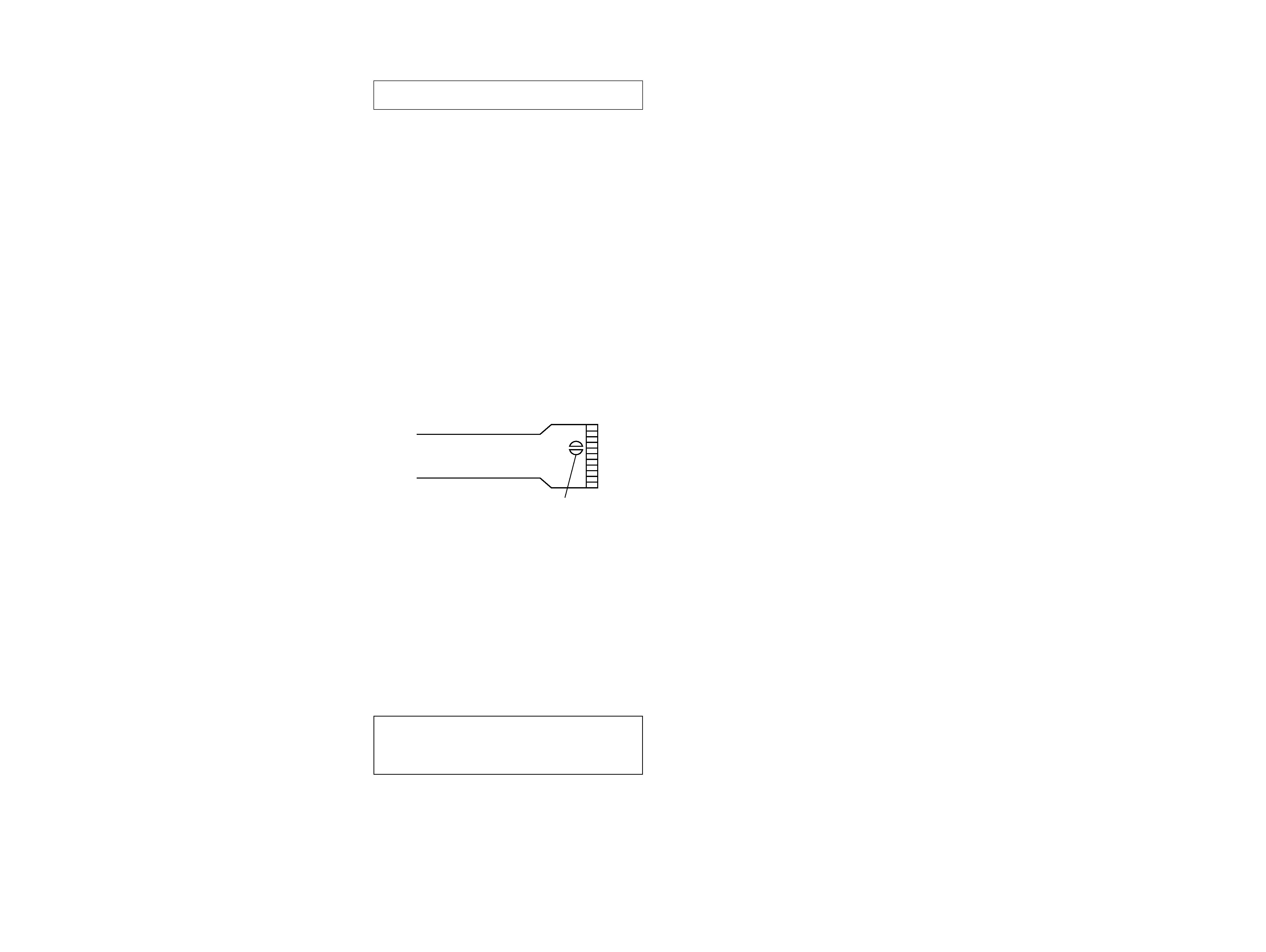
NOTES ON HANDLING THE OPTICAL PICK-UP BLOCK
(KMS-241C).
The laser diode in the optical pick-up block may suffer electro-
static break-down easily. When handling it, perform soldering
bridge to the laser-tap on the flexible board. Also perform mea-
sures against electrostatic break-down sufficiently before the op-
eration. The flexible board is easily damaged and should be
handled with care.
laser-tap
OPTICAL PICK-UP FLEXIBLE BOARD
4
MDX-M690
SECTION 1
SERVICING NOTES
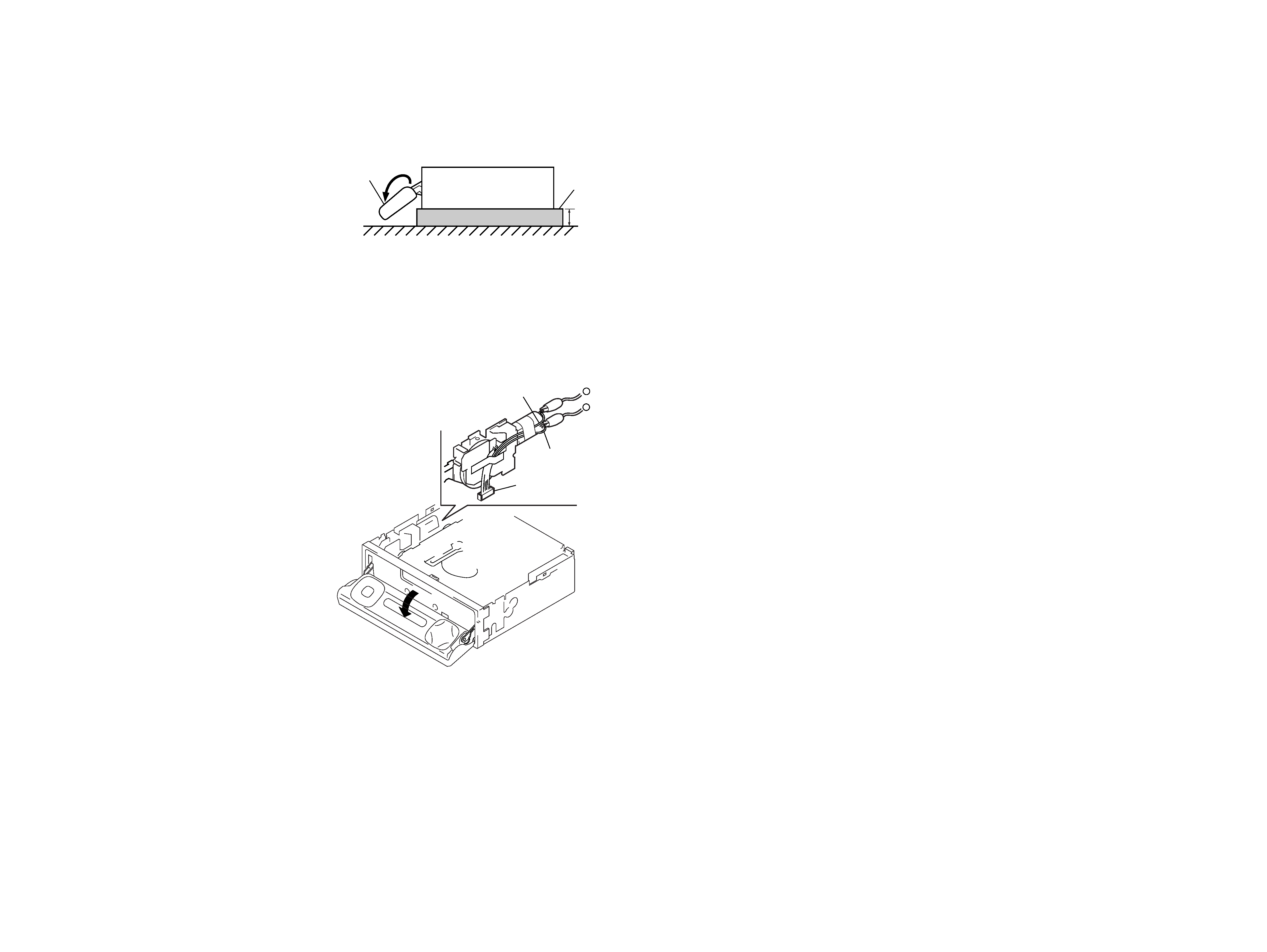
PRECAUTION ON OPEN/CLOSE FRONT PANEL
The front panel opens to the bottom of main unit.
In performing the repair, place the main unit on the base having
the height exceeding 1 cm.
Open the front panel by supplying the power through the follow-
ing steps:
1. Disconnect the motor connector (CN602) from main board.
2. Supply the power to the motor.
Voltage
: 9 V
Yellow wiring : MOTOR
Black wiring : MOTOR +
front panel
MDX-M690
( SIDE VIEW)
1cm
base
black wiring
yellow wiring
connector
(CN602)
+
DETACHING THE DISPLAY PANEL IN THE TEST MODE
In the normal mode, after pressing the [OPEN] key for two sec-
onds to set the front panel in detaching position and detaching the
display panel is complete, the front panel closes automatically.
But in the test mode, the front panel opens automatically. (refer to
page 20 for test mode)
MDX-M690
5
5
SECTION 2
GENERAL
This section is extracted from
instruction manual.
4
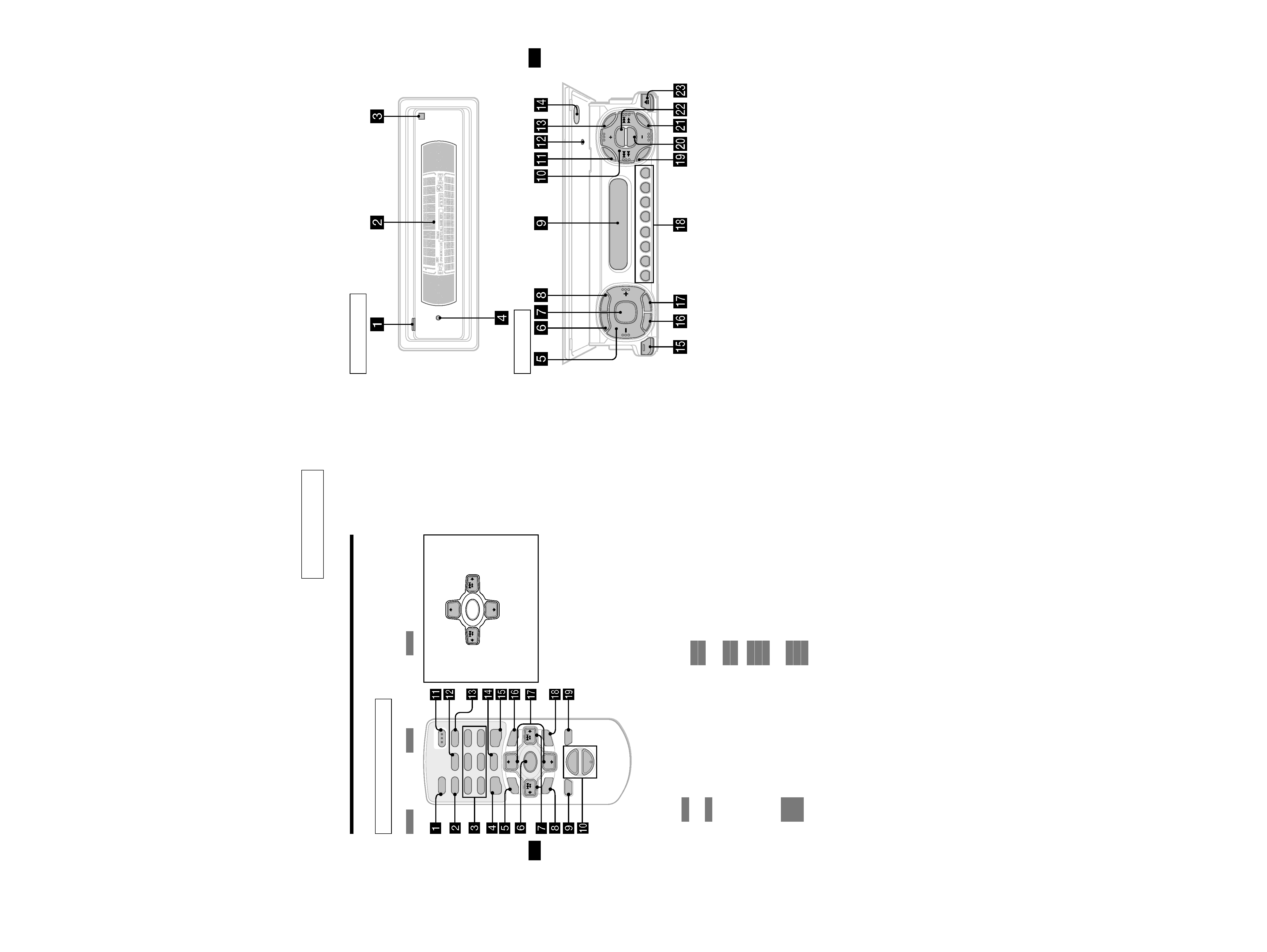
Location of controls
Refer to the pages listed for details.
: During Playback
: During radio reception
: During menu mode
a SCRL (scroll) button 12
b DSPL/PTY (display mode change/
programme type) button 12, 13, 17,
20, 25, 35
c Number buttons
(1) REP 12
(2) SHUF 12
15, 16, 18, 19, 22, 24
d EQ7 button 26
e MENU button 10, 13, 14, 15, 19, 21,
23, 25, 26, 27, 28, 30, 31, 33, 34, 35
f SOURCE (Power on/Radio/CD/MD)
button 10, 11, 13, 15, 16, 19, 22, 26,
27, 29, 30, 31, 33, 35
g
</, SEEK +/ buttons 10, 28, 29, 30,
31
11
16, 18, 22
10, 13, 14, 15, 21, 23, 25, 26,
27, 28, 30, 31, 33, 34, 35
h SOUND button 28, 29, 30, 31
i OFF (Stop/Power off) button 11, 35
j VOL +/ buttons 19
k OPEN/CLOSE button 11, 37
l AF button 18, 19
m TA button 19
n MODE button
11, 13
15, 16, 19, 22
o DSO button 27
p LIST button
13, 14
17, 24
q
M/m DISC +/ buttons
11, 14
16, 17, 20, 22, 23, 24, 25
10, 13, 14, 15, 19, 21, 23, 25,
26, 27, 28, 30, 31, 33, 34, 35
r ENTER button
14
17, 20, 23, 24, 25
10, 13, 14, 15, 19, 21, 23, 25,
26, 27, 30, 31, 33, 34, 35
s ATT button 33
Card remote commander RM-X111
CD/MD
RADIO
MENU
DISC
ATT
OFF
SCRL
DSPL
1
4
AF
MODE
2
5
TA
3
6
SOURCE
DISC +
SEEK+
SEEK
SOUND
ENTER
MENU
LIST
EQ7
DSO
VOL
+
OPEN/CLOSE
PTY
REP
SHUF
DISC
SOURCE
DISC +
SEEK+
SEEK
< (SEEK)
(): to select
leftwards/
.
, (SEEK)
(+): to select
rightwards/
>
M (DISC)
(+): to select upwards
In menu mode, the currently selectable button (s) of
these four are indicated with a "
v" in the display.
m (DISC)
(): to select downwards
Note
If the unit is turned off by pressing (OFF) for 2
seconds, the unit cannot be operated with the card
remote commander unless (SOURCE) on the unit is
pressed, or a disc is inserted to activate the unit first.
Tip
Refer to "Replacing the lithium battery" for details on
how to replace the batteries (page 36).
CD/MD
RADIO
CD/MD
RADIO
MENU
CD/MD
RADIO
CD/MD
RADIO
CD/MD
RADIO
MENU
CD/MD
RADIO
MENU
5
The corresponding buttons of the unit
control the same functions as those on
the card remote commander.
a OPEN button 9, 11, 37
b Main display window
c
qf Receptor for the card remote
commander
d
qs Reset button 9
e Volume adjust buttons
f SCRL (scroll) button
g SOURCE button
h DSPL/PTY (display mode change/
programme type) button
i Sub display window
j DISC +/ (cursor up/down) buttons
SEEK /+ (cursor left/right) buttons
k MENU button
m LIST button
o CLOSE (front panel close) button 9, 11
p OFF (Stop/Power off) button*
q MODE button
r Number buttons
s SOUND button
t EQ7 button
u ENTER button
v DSO button
w
Z (eject) button 11
Main display panel
Operation side
CLOSE
OFF
MODE
SOURCE
ENTER
SOUND
M
EN
U
LIST
DISC
RESET
DISC
DSO
REP
SHUF
EQ7
AF
TA
12
3
4
5
6
SCRL
DSPLPT
Y