SERVICE MANUAL
MDX-C7900
FM/AM MINIDISC PLAYER
MDX-C7900R
FM/MW/LW MINIDISC PLAYER
US Model
Canadian Model
E Model
MDX-C7900
AEP Model
UK Model
MDX-C7900R
Model Name Using Similar Mechanism
NEW
Base Mechanism Type
MG-164KT-138
Optical Pick-Up Name
KMS-241A/J2N
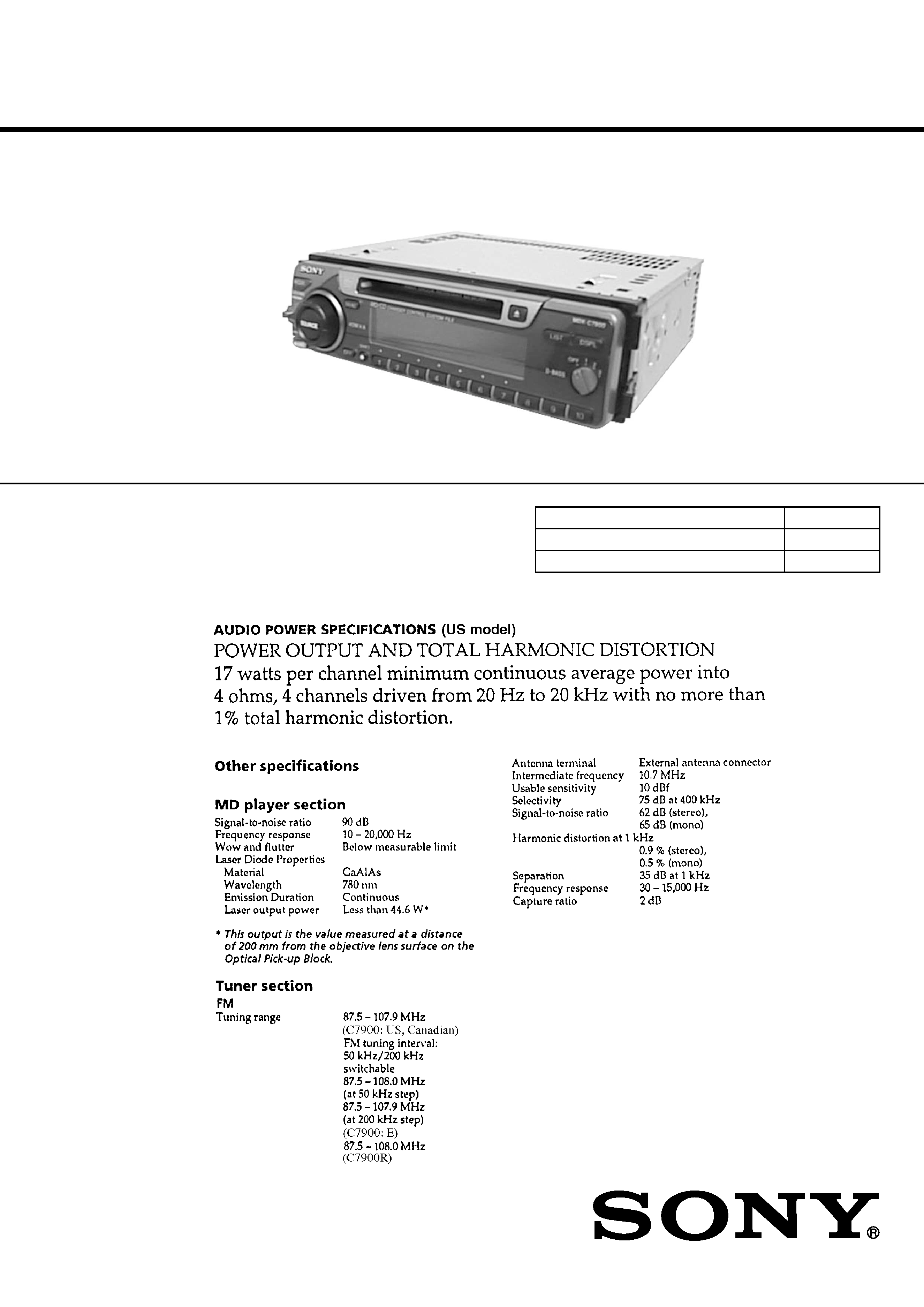
SPECIFICATIONS
MDX-C7900/C7900R
Refer to RM-X4S Service Manual (9-925-
698-[][]) issued previously for information
of remote commander (RM-X4S) supplied
with this set.
Photo: MDX-C7900
Continued on next page
9-925-787-12
Sony Corporation
2001H0500-1
e Vehicle Company
C
2001.8
Shinagawa Tec Service Manual Production Group
Ver 1.1 2001.08
2
TABLE OF CONTENTS
1.
SERVICE NOTE ....................................................... 3
2.
GENERAL
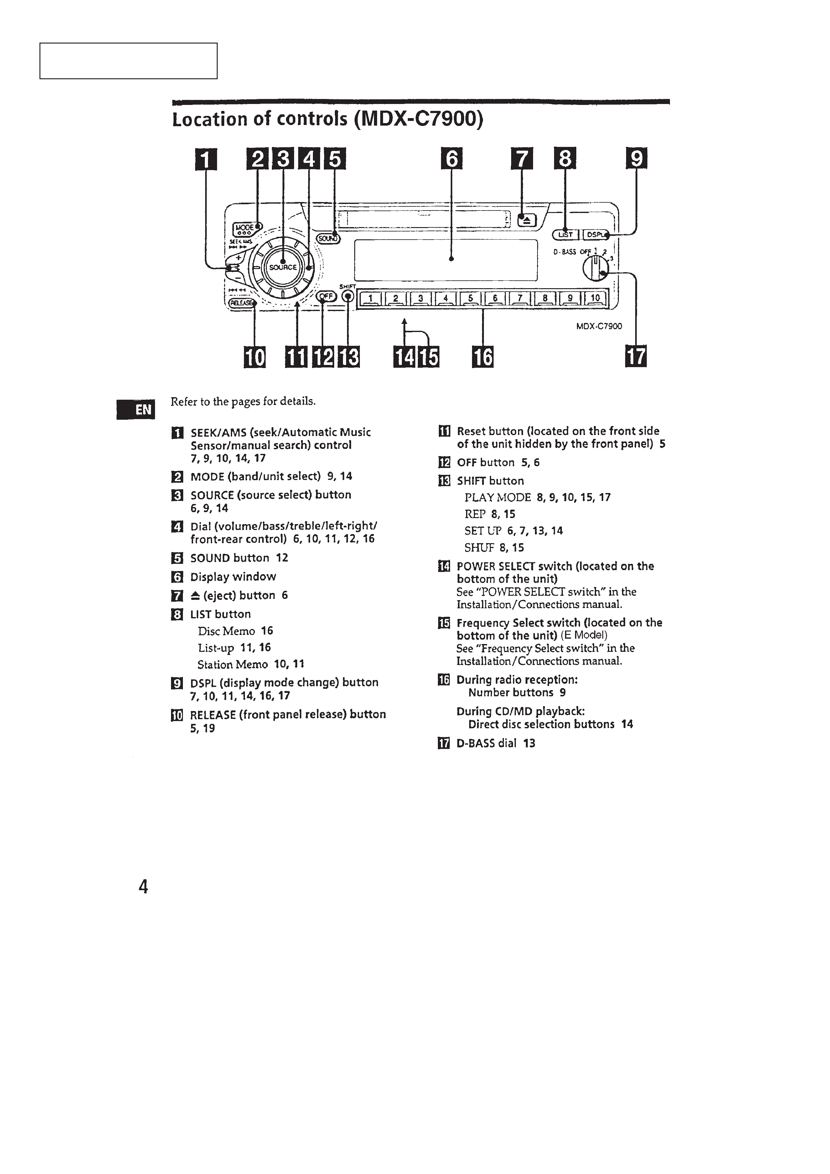
Location of Controls (MDX-C7900) .............................. 4
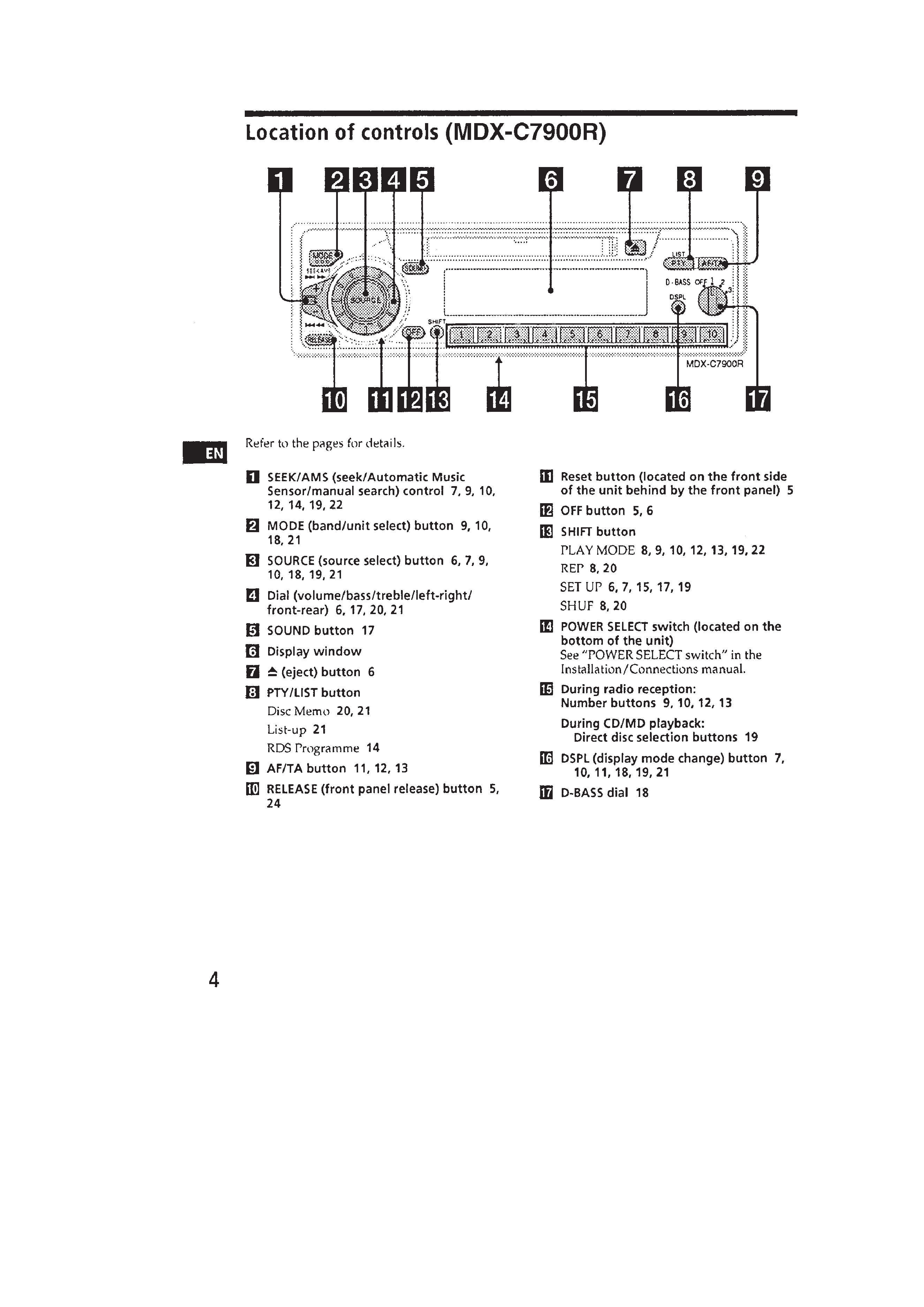
Location of Controls (MDX-C7900R) ........................... 5
Resetting the Unit ........................................................... 6
Detaching the Front Panel ............................................... 6
Preparing the Rotary Commander .................................. 6
Setting the Clock ............................................................. 6
Installation (US, Canadian) ............................................ 7
Installation (AEP, UK, E) ............................................... 8
Connections ..................................................................... 10
3.
DISASSEMBLY ......................................................... 13
4.
ELECTRICAL ADJUSTMENTS
Test Mode ........................................................................ 18
MD Section ..................................................................... 18
Tuner Section .................................................................. 18
5.
DIAGRAMS
5-1. Block Diagram SERVO Section ............................... 21
5-2. Block Diagram MAIN Section ................................. 23
5-3. Block Diagram
DISPLAY/KEY CONTROL Section ........................ 25
5-4. Block Diagram
BUS CONTROL/POWER SUPPLY Section ........... 27
5-5. Printed Wiring Boards
MECHANISM DECK Section ................................. 29
5-6. Schematic Diagram
MECHANISM DECK Section ................................. 31
5-7. Schematic Diagram MAIN Section .......................... 35
5-8. Printed Wiring Board MAIN Section ....................... 39
5-9. Printed Wiring Board PANEL Section ..................... 43
5-10. Schematic Diagram PANEL Section ........................ 45
5-11. IC Pin Function Description ........................................... 55
6.
EXPLODED VIEWS ................................................ 64
7.
ELECTRICAL PARTS LIST ............................... 68
Ver 1.1
3
Flexible Circuit Board Repairing
· Keep the temperature of the soldering iron around 270 °C dur-
ing repairing.
· Do not touch the soldering iron on the same conductor of the
circuit board (within 3 times).
· Be careful not to apply force on the conductor when soldering
or unsoldering.
Notes on chip component replacement
· Never reuse a disconnected chip component.
· Notice that the minus side of a tantalum capacitor may be dam-
aged by heat.
ATTENTION AU COMPOSANT AYANT RAPPORT
À LA SÉCURITÉ!
LES COMPOSANTS IDENTIFIÉS PAR UNE MARQUE
!
SUR LES DIAGRAMMES SCHÉMATIQUES ET LA LISTE
DES PIÈCES SONT CRITIQUES POUR LA SÉCURITÉ
DE FONCTIONNEMENT. NE REMPLACER CES COM-
POSANTS QUE PAR DES PIÈCES SONY DONT LES
NUMÉROS SONT DONNÉS DANS CE MANUEL OU
DANS LES SUPPLÉMENTS PUBLIÉS PAR SONY.
SAFETY-RELATED COMPONENT WARNING!!
COMPONENTS IDENTIFIED BY MARK
! OR DOTTED
LINE WITH MARK
! ON THE SCHEMATIC DIAGRAMS
AND IN THE PARTS LIST ARE CRITICAL TO SAFE
OPERATION. REPLACE THESE COMPONENTS WITH
SONY PARTS WHOSE PART NUMBERS APPEAR AS
SHOWN IN THIS MANUAL OR IN SUPPLEMENTS PUB-
LISHED BY SONY.
CAUTION
Use of controls or adjustments or performance of procedures
other than those specified herein may result in hazardous ra-
diation exposure.
SECTION 1
SERVICE NOTE
· Type A/B Discrimination
[MAIN BOARD] (Component Side)
IC700
MB90574PFV-G-113-BND (C7900R: Type A)
MB90574PFV-G-114-BND (C7900: Type A)
MB90F574PFV-G-113 (C7900R: Type B)
MB90F574PFV-G-114 (C7900: Type B)
4
SECTION 2
GENERAL
This section is extracted from
instruction manual.
5