MDS-PC3
SPECIFICATIONS
SERVICE MANUAL
Model Name Using Similar Mechanism
MDS-JE640
MD Mechanism Type
MDM-7A
Optical Pick-up Type
KMS-260B/J1N
US Model
Canadian Model
AEP Model
UK Model
E Model
US and foreign patents licensed form Dolby Laboratories
Licensing Corporation.
Photo: SILVER
System
MiniDisc digital audio system
Disc
MiniDisc
Laser
Semiconductor laser (
= 780 nm)
Emission duration: continuous
Laser output
Less than 44.6
µW*
* This output is the value
measured at a distance of
200 mm from the objective lens
surface on the Optical Pick-up
Block with 7 mm aperture.
Laser diode
Material: GaAlAs
Revolutions (CLV)
400 rpm to 900 rpm
Error correction
Advanced Cross Interleave Reed
Solomon Code (ACIRC)
Sampling frequency
44.1 kHz
Coding
Adaptive Transform Acoustic
Coding (ATRAC)
Modulation system
EFM (Eight-to-Fourteen
Modulation)
Number of channels
2 stereo channels
Frequency response
5 to 20,000 Hz
±0.5 dB
Signal-to-noise ratio
Over 94 dB during playback
Wow and flutter
Below measurable limit
Inputs
LINE (ANALOG) IN
Jack type: stereo-mini
Impedance: 47 kilohms
Rated input: 500 mVrms
Minimum input: 125 mVrms
DIGITAL (OPTICAL) IN Connector type: square optical
Impedance: 660 nm (optical wave
length)
Outputs
LINE (ANALOG) OUT (VARIABLE)
Jack type: stereo-mini
Rated output: 1 Vrms (at
50 kilohms)
Load impedance: Over 10 kilohms
DIGITAL (OPTICAL) OUT
Connector type: square optical
Rated output: 18 dBm
Impedance: 660 nm (optical wave
length)
PHONES
Jack type: stereo-mini
Rated output: 5 mW
Load impedance: 32 ohms
General
Where purchased
Power requirements*
U.S.A. and Canada
120 V AC, 60 Hz
Other countries
220 230 V AC, 50/60 Hz
* Using an AC power adaptor (supplied)
Power consumption
7 W
Dimensions (approx.)
152
× 52 × 255 mm (6 × 2 1/8 ×
10 1/8 inches) (w/h/d) incl.
projecting parts and controls
Mass (approx.)
1.0 kg (2 lb 4 oz)
Supplied
accessories
· AC power adaptor (1)
·Audio connecting cord
(stereo mini-plug
× 1 y stereo mini-plug × 1)
(1)
·Optical cable (1)
·Remote commander (remote) RM-D52M (1)
· PC connecting kit PCLK-MN10* (1)
* Required for operation by personal computer. For
details, refer to the operating instructions supplied
with the PCLK-MN10.
Ver. 1.1 2005.03
Sony Corporation
Audio Group
Published by Sony Engineering Corporation
9-929-545-12
2005C02-1
© 2005.03
MINIDISC DECK
2
SELF-DIAGNOSIS FUNCTION
The self-diagnosis function consists of error codes for customers which are displayed automatically when errors occur, and error codes which
show the error history in the test mode during servicing. For details on how to view error codes for the customer, refer to the following box
in the instruction manual. For details on how to check error codes during servicing, refer to the following "Procedure for using the Self-
Diagnosis Function (Error History Display Mode)".
Procedure for using the Self-Diagnosis Function (Error History Display Mode).
Note: Perform the self-diagnosis function in the "error history display mode" in the test mode. The following describes the least required
procedure. Be careful not to enter other modes by mistake. If you set other modes accidentally, press the x/Z button to exit the
mode.
Self-Diagnosis Function
The deck's self-diagnosis function automatically checks the condition of the MD deck when an error
occurs, then issues a three-digit code and an error message on the display. If the code and message
alternate, find them in the following table and perform the indicated countermeasure. Should the problem
persist, consult your nearest Sony dealer.
Three-digit code/Message
Cause/Remedy
C11/Protected
The inserted MD is record-protected.
, Take out the MD and close the record-protect slot (page 13).
C12/Cannot Copy
An attempt was made to play a disc that is not compatible with this deck
(MD data disc, etc.).
, Replace the disc.
C13/Rec Error
The recording was not made properly.
, Set the deck in a stable surface, and repeat the recording procedure.
The inserted MD is dirty (with smudges, fingerprints, etc.), scratched, or
substandard in quality.
, Replace the disc and repeat the recording procedure.
C13/Read Error
The deck could not read the TOC on the MD properly.
, Take out the MD and insert it again.
C14/Toc Error
The deck could not read the TOC on the MD properly.
, Insert another disc.
, If possible, erase all the tracks on the MD (page 29).
C41/Cannot Copy
The digitally dubbed material cannot be recorded digitally (page 11).
C71/Din Unlock
The sporadic appearance of this message is caused by the digital signal being
recorded. This will not affect the recording.
While recording from a digital component connected through the DIGITAL
(OPTICAL) IN connector, the digital connecting cable was unplugged or the
digital component turned off.
, Connect the cable or turn the digital component back on.
E0001/MEMORY NG
There is an error in the internal data that the deck needs in order to operate.
, Consult your nearest Sony dealer.
E0101/LASER NG
There is a problem with the optical pickup.
, Consult your nearest Sony dealer.
*Note:
As this unit has only a few buttons, one button is assigned with several functions in the test mode."
Press the z button, AMS knob to switch the functions.
· Each time the z button is pressed, the display switches in the follwing order, "PGM" t "blank" t "PGM" t .
· Rotate the AMS knob and the display switches in the following order, "blank" t "TOC" t "EDIT" t "TOC EDIT" t
"[
]" t "[TOC
]" t "[
EDIT]" t "[TOC EDIT]" t "blank" t .
For simplicity, operations of z button will not be discribed here.
Example)
x/Z : Lights-out "PGM" and press the x/Z button.
x/Z "PGM" : Display "PGM" and press the x/Z button.
The functions of each button change with the display.
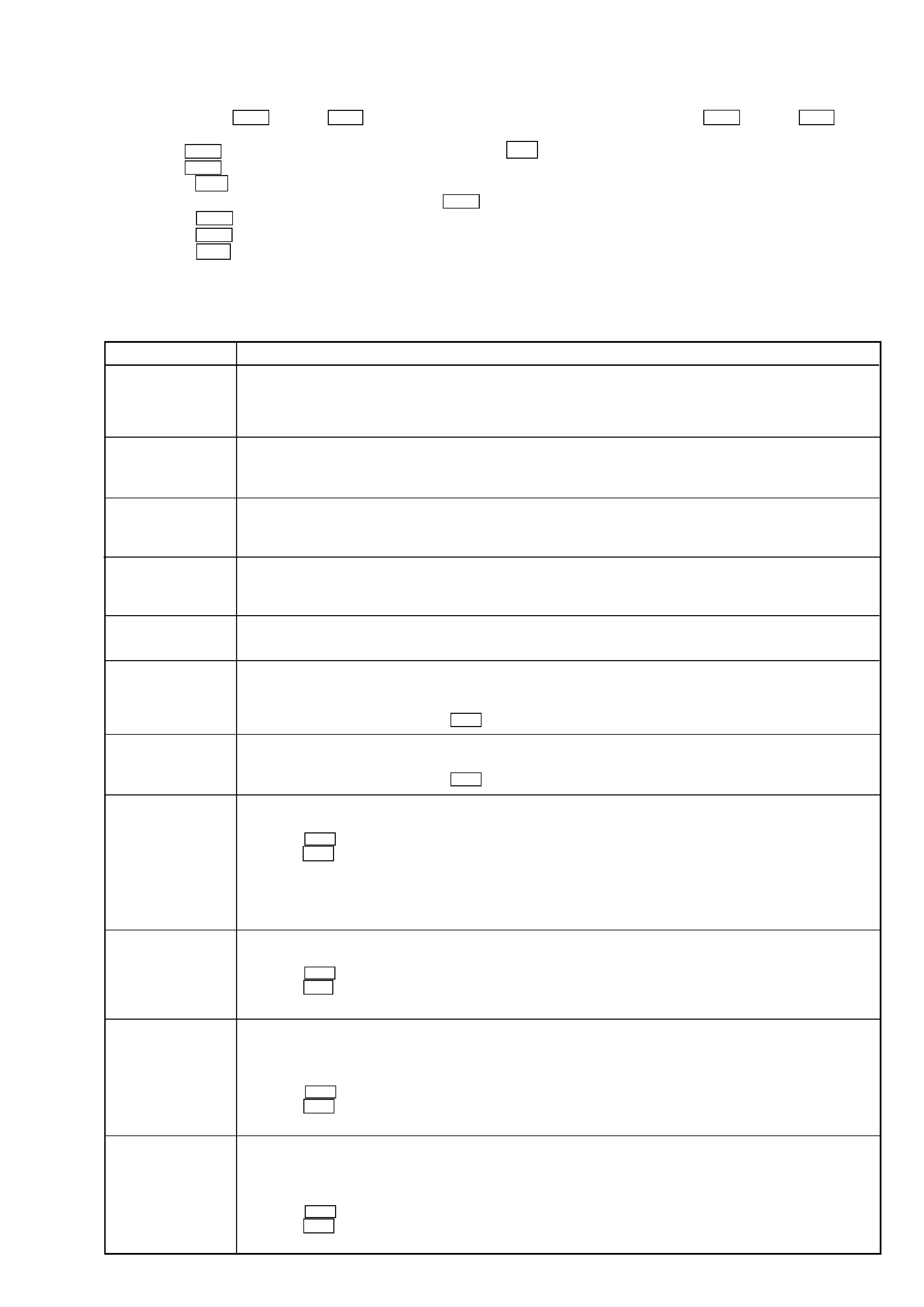
Bottons and Corresponding Functions
"PGM" Lights-out
LCD displayed
Buttons
"PGM"
displayed
Nothing
TOC
EDIT
TOC EDIT
TOC
EDIT
TOC EDIT
displayed
@/1
@/1
ENTER
REPEAT
PLAY
CLEAR
FF
PLAY
DISPLAY
--
(YES)
MODE
MENU
x/Z
EJECT
(EDIT)/
STOP
REC
--
FR
SCROLL
TIME
--
NO
3
1. While pressing the AMS knob and x/Z button, connect the power plug to the outlet, and release the AMS knob and x/Z button.
When the test mode is set, "[Check]" will be displayed.
2. Rotate the AMS knob and when "[Service]" is displayed, press the @/1 button.
3. Rotate the AMS knob and display "Err Display".
4. Pressing the @/1 button sets the error history mode and displays "op rec tm".
5. Select the contents to be displayed or executed using the AMS knob.
6. Pressing the AMS knob will display or execute the contents selected.
7. Pressing the AMS knob another time returns to step 4.
8. Pressing the x/Z button displays "Err Display" and exits the error history mode.
9. To exit the test mode, remove the power plug to the outlet.
ITEMS OF ERROR HISTORY MODE ITEMS AND CONTENTS
Selecting the Test Mode
Display
op rec tm
op play tm
spdl rp tm
retry err
total err
err history
retry adrs
er refresh
tm refresh
op change
spdl change
History
Displays the total recording time.
When the total recording time is more than 1 minute, displays the hour and minute
When less than 1 minute, displays "Under 1 min"
The display time is the time the laser is set to high power, which is about 1/4 of the actual recording time.
Displays the total playback time.
When the total playback time is more than 1 minute, displays the hour and minute
When less than 1 minute, displays "Under 1 min"
Displays the total rotating time of the spindle motor.
When the total rotating time is more than 1 minute, displays the hour and minute
When less than 1 minute, displays "Under 1 min"
Displays the total number of retry errors during recording and playback
Displays "r xx p yy". xx is the number of errors during recording. yy is the number of errors during playback.
This is displayed in hexadecimal from 00 to FF.
Displays the total number of errors
Displays "total xx". This is displayed in hexadecimal from 00 to FF.
Displays the past ten errors.
Displays "0x ErrCd@@".
X is the history number. The younger the number, the more recent is the history (00 is the latest). @@ is the error code.
Select the error history number using the AMS knob.
Displays the past five retry addresses.
Displays "xx ADRS yyyy", xx is the history number, yyyy is the cluster with the retry error.
Select the error history number using the AMS knob.
Mode for erasing the error and retry address histories
Procedure
1. Press the AMS knob when displayed as "er refresh".
2. Press the @/1 button when the display changes to "er refresh?".
When "complete!" is displayed, it means erasure has completed.
Be sure to check the following after executing this mode.
*Data has been erased.
*Perform recording and playback, and check that the mechanism is normal.
Mode for erasing the total time of recording and playback
Procedure
1. Press the AMS knob when displayed as "tm refresh".
2. Press the @/1 button when the display changes to "tm refresh?".
When "complete!" is displayed, it means erasure has completed.
Mode for erasing the total time of op rec tm, op play tm.
These histories are based on the time of replacement of the optical pickup. If the optical pick-up has been replaced, perform this
procedure and erase the history.
Procedure
1. Press the AMS knob when displayed as "op change".
2. Press the @/1 button when the display changes to "op change?".
When "Complete!" is displayed, it means erasure has completed.
Mode for erasing the total spdl rp tm time
These histories are based on the time of replacement of the spindle motor. If the spindle motor has been replaced, perform this
procedure and erase the history.
Procedure
1. Press the AMS knob when displayed as "spdl change"
2. Press the @/1 button when the display changes to "spdl change?"
When "Complete!" is displayed, it means erasure has completed.

4
Description
TABLE OF CONTENTS
1. SERVICING NOTES ............................................. 5
2. GENERAL ........................................................................ 11
3. DISASSEMBLY
3-1. Case (U) .............................................................................. 14
3-2. MD Mechanism Deck (MDM-74) ...................................... 14
3-3. Main Board ......................................................................... 15
3-4. Over Light Head (HR901), BD (MD) Board ...................... 15
3-5. Holder Assy ......................................................................... 16
3-6. Loading Motor Assy (M103) .............................................. 16
3-7. Sled Motor Assy (M102), Slider ......................................... 17
3-8. Optical Pick-up (MD) (KMS-260B/JIN) ............................ 17
3-9. Spindle Motor Assy (M101) ............................................... 18
4. TEST MODE ..................................................................... 19
5. ELECTRICAL ADJUSTMENTS ............................... 24
6. DIAGRAMS
6-1. Block Diagrams
· BD Section ....................................................................... 36
· Main Section .................................................................... 37
6-2. Printed Wiring Board BD Section ................................. 38
6-3. Schematic Diagram BD Section (1/2) ........................... 39
6-4. Schematic Diagram BD Section (2/2) ........................... 40
6-5. Printed Wiring Board Main Section .............................. 41
6-6. Schematic Diagram Main Section (1/2) ........................ 42
6-7. Schematic Diagram Main Section (2/2) ........................ 43
6-8.
Printed Wiring Board Panel Section ........................... 44
6-9. Schematic Diagram Panel Section ............................... 45
6-10. IC Block Diagrams ........................................................... 46
6-11. IC Pin Functions ............................................................... 49
7. EXPLODED VIEWS
7-1. Chassis Section ................................................................... 54
7-2. Mechanism Section-1 (MDM-7A) ...................................... 55
7-3. Mechanism Section-2 (MDM-7A) ...................................... 56
8. ELECTRICAL PARTS LIST ........................................ 57
Table of Error Codes
Error Code
10
12
20
21
22
23
24
30
31
40
41
42
43
50
51
Could not load
Loading switches combined incorrectly
Timed out without reading the top of PTOC
Could read top of PTOC, but detected error
Timed out without accessing UTOC
Timed out without reading UTOC
Error in UTOC
Could not start playback
Error in sector
Retry cause generated during normal recording
Retried in DRAM overflow
Retry occurred during TOC writing
Retry aborted during S.F editing
Other than access processing, and could not read address.
Focus NG occurred and overran.
5
SECTION 1
SERVICE NOTES
This appliance is classified as a
CLASS 1 LASER product. The
CLASS 1 LASER PRODUCT
MARKING is located on the
rear exterior.
Laser component in this product is capable
of emitting radiation exceeding the limit for
Class 1.
CAUTION
Use of controls or adjustments or performance of procedures
other than those specified herein may result in hazardous radia-
tion exposure.
Notes on chip component replacement
· Never reuse a disconnected chip component.
· Notice that the minus side of a tantalum capacitor may be
damaged by heat.
Flexible Circuit Board Repairing
· Keep the temperature of soldering iron around 270°C
during repairing.
· Do not touch the soldering iron on the same conductor of the
circuit board (within 3 times).
· Be careful not to apply force on the conductor when soldering
or unsoldering.
NOTES ON HANDLING THE OPTICAL PICK-UP
BLOCK OR BASE UNIT
The laser diode in the optical pick-up block may suffer electrostatic
break-down because of the potential difference generated by the
charged electrostatic load, etc. on clothing and the human body.
During repair, pay attention to electrostatic break-down and also
use the procedure in the printed matter which is included in the
repair parts.
The flexible board is easily damaged and should be handled with
care.
NOTES ON LASER DIODE EMISSION CHECK
Never look into the laser diode emission from right above when
checking it for adjustment. It is feared that you will lose your sight.
SAFETY-RELATED COMPONENT WARNING!!
COMPONENTS IDENTIFIED BY MARK 0 OR DOTTED LINE WITH
MARK 0 ON THE SCHEMATIC DIAGRAMS AND IN THE PARTS
LIST ARE CRITICAL TO SAFE OPERATION. REPLACE THESE
COMPONENTS WITH SONY PARTS WHOSE PART NUMBERS
APPEAR AS SHOWN IN THIS MANUAL OR IN SUPPLEMENTS
PUBLISHED BY SONY.
ATTENTION AU COMPOSANT AYANT RAPPORT
À LA SÉCURITÉ!
LES COMPOSANTS IDENTIFÉS PAR UNE MARQUE 0 SUR LES
DIAGRAMMES SCHÉMATIQUES ET LA LISTE DES PIÈCES SONT
CRITIQUES POUR LA SÉCURITÉ DE FONCTIONNEMENT. NE
REMPLACER CES COMPOSANTS QUE PAR DES PIÈSES SONY
DONT LES NUMÉROS SONT DONNÉS DANS CE MANUEL OU
DANS LES SUPPÉMENTS PUBLIÉS PAR SONY.
This caution
label is located
inside the unit.
Lead free soldering
MAIN and PANEL boards of this product are lead free soldered
(contains no lead).
Lead-free solder have the following characteristics.
· The melting point is about 40 ºC higher than conventional solder.
Conventional soldering iron can be used, but must be pressed for
a longer time.
When using the soldering iron with a temperature adjustment func-
tion, set to about 350 ºC.
Note: Pressing the soldering iron too long may cause the board pat-
tern (copper coating) to peel off.
· Strong viscosity
As it has stronger viscosity than conventional solder, make sure
the IC terminal does not solder bridge.
· Can be used with conventional solder
Though it is best to add lead-free solder only, conventional solder
can also be added.
· Boards using lead-free solder are printed with the LF mark mean-
ing "Lead Free".
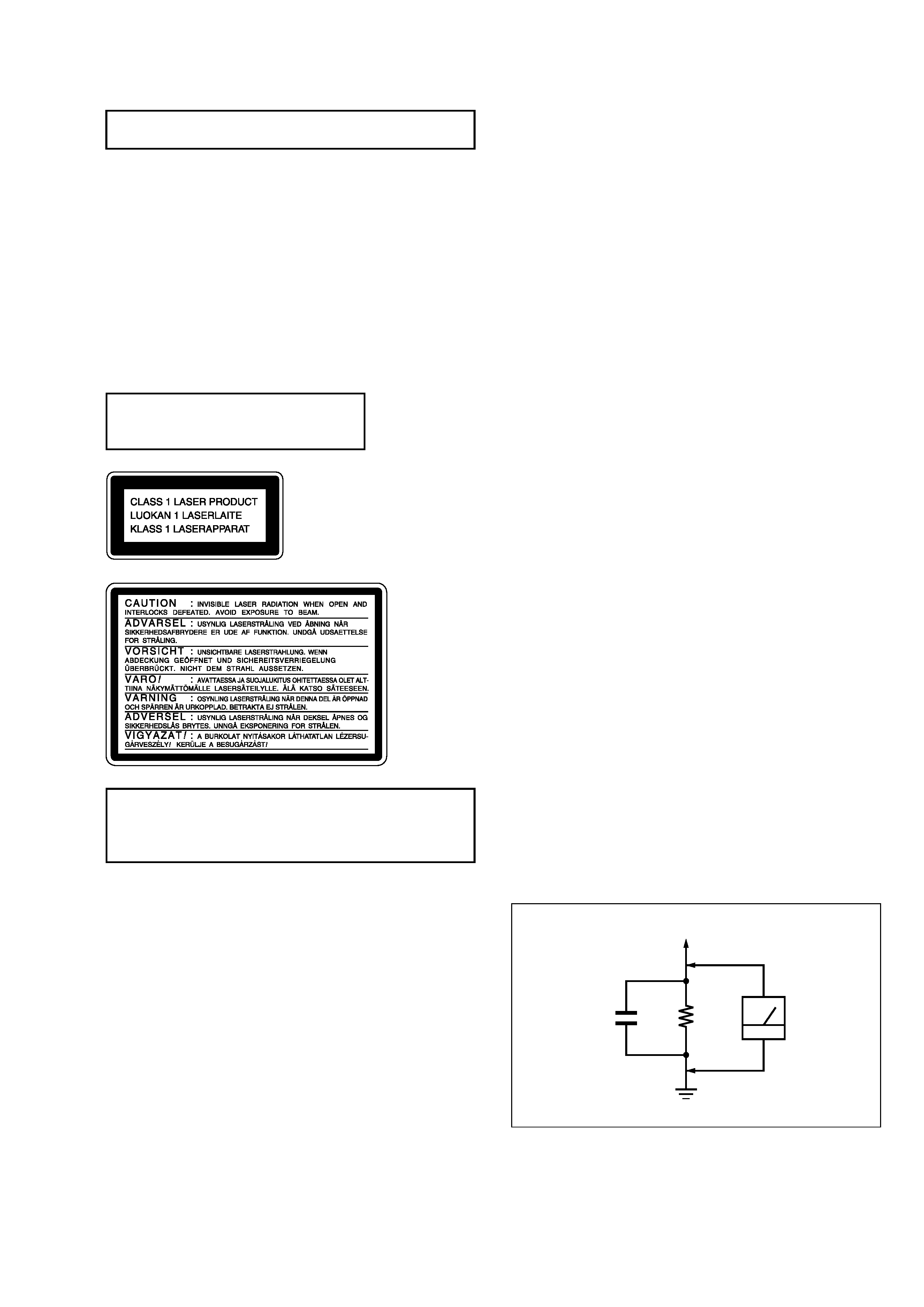
Fig. A.
Using an AC voltmeter to check AC leakage.
1.5 k
0.15
µF
AC
voltmeter
(0.75 V)
To Exposed Metal
Parts on Set
Earth Ground
SAFETY CHECK-OUT
After correcting the original service problem, perform the follow-
ing safety check before releasing the set to the customer:
Check the antenna terminals, metal trim, "metallized" knobs, screws,
and all other exposed metal parts for AC leakage.
Check leakage as described below.
LEAKAGE TEST
The AC leakage from any exposed metal part to earth ground and
from all exposed metal parts to any exposed metal part having a
return to chassis, must not exceed 0.5 mA (500 microamperes). Leak-
age current can be measured by any one of three methods.
1. A commercial leakage tester, such as the Simpson 229 or RCA
WT-540A. Follow the manufacturers' instructions to use these
instruments.
2. A battery-operated AC milliammeter. The Data Precision 245
digital multimeter is suitable for this job.
3. Measuring the voltage drop across a resistor by means of a VOM
or battery-operated AC voltmeter. The "limit" indication is 0.75
V, so analog meters must have an accurate low-voltage scale.
The Simpson 250 and Sanwa SH-63Trd are examples of a pas-
sive VOM that is suitable. Nearly all battery operated digital
multimeters that have a 2 V AC range are suitable. (See Fig. A)