1
MDS-LSA1
SPECIFICATIONS
SERVICE MANUAL
MINIDISC DECK
Model Name Using Similar Mechanism
NEW
MD Mechanism Type
MDM-7X2B
Optical Pick-up Type
KMS-262A/J1N
AEP Model
UK Model
E Model
Australian Model
System
MiniDisc digital audio system
Disc
MiniDisc
Laser
Semiconductor laser (
= 780 nm)
Emission duration: continuous
Laser output
Less than 44.6
µW*
* This output is the value measured
at a distance of 200 mm from the
objective lens surface on the Optical
Pick-up Block with 7 mm apertur e.
Laser diode
Material: GaAlAs
Revolutions (CLV)
400 rpm to 900 rpm
Error correction
ACIRC (Advanced Cross Interleave
Reed Solomon Code)
Sampling frequency
44.1 kHz
Coding
ATRAC (Adaptive TRansform
Acoustic Coding)/ATRAC3
Modulation system
EFM (Eight-to-Fourteen Modulation)
Number of channels
2 stereo channels
Frequency response
5 to 20,000 Hz
±0.3 dB
Signal-to-noise ratio
Over 100 dB during playback
Wow and flutter
Inputs/outputs
i.LINK S200
Jack type: 4-pins to 4-pins
General
Power requirements
230 V AC, 50/60 Hz
Power consumption
18 W
Dimensions (approx.)
430 x 70 x 315 mm (w/h/d) incl.
projecting parts and controls
Mass (approx.)
4.4 kg
Supplied accessories
Design and specifications are subject to change without notice.
· i.LINK connecting cable (1)
· Remote commander (remote) (1)
Below measurable limit
US and foreign patents licensed from Dolby Laboratories
Licensing Corporation.

2
SELF-DIAGNOSIS FUNCTION
The self-diagnosis function consists of error codes for customers which are displayed automatically when errors occur, and error codes which
show the error history in the test mode during servicing. For details on how to view error codes for the customer, refer to the following box
in the instruction manual. For details on how to check error codes during servicing, refer to the following "Procedure for using the Self-
Diagnosis Function (Error History Display Mode)".
Self-Diagnosis Function
The deck's self-diagnosis function automatically checks the condition of the MD deck when an error occurs, then issues a
code and an error message on the display . If the code and message alternate, find them in the following table and perform
the indicated countermeasure. Should the problem persist, consult your near est Sony dealer .
Code/Message
Cause/Remedy
C11/Pr otected
The inserted MD is recor d-protected.
, Take out the MD and close the recor d-protect slot (page 13).
C12/Cannot Copy
An attempt was made to play a disc that is not compatible with this deck (MD data disc, etc.).
, Replace the disc.
C13/REC Err or
The recor ding was not made properly .
, Set the deck in a stable surface, and repeat the recor ding procedure.
The inserted MD is dirty (with smudges, fingerprints, etc.), scratched, or substandard in quality.
, Replace the disc and repeat the recording procedure.
C13/Read Err or
The deck could not read the TOC on the MD properly.
, Take out the MD and insert it again.
C14/T oc Err or
The deck could not read the TOC on the MD properly.
, Insert another disc.
, If possible, erase all the tracks on the MD (page 29).
C41/Cannot Copy
The digitally dubbed material cannot be recorded digitally (page 14).
C71/Din Unlock
The sporadic appearance of this message is caused by the digital signal being recor ded. This will not af fect
the recor ding.
While recor ding from a digital component connected through the i.LINK S200 connector , the digital
connecting cable was unplugged
or the digital component turned off.
, Connect the cable or turn the digital component back on.
C78:03/LOOP CONNECT
The i.LINK connection is looped.
, Check the connection (see page 39).
C78:04/NO SIGNAL
The selected component is turned on, but no signal is not output from the component.
, Check the selected component.
C78:11/C78:12/CANNOT
LINC
The deck cannot establish a LINC with a component because of an existing LINC between the deck and
another component.
, Cancel the LINC between the deck and the other component.
C78:15/BUS FULL
The signal bus within the i.LINK configuration is full and no more signals can be output from the deck.
C78:21/NO SIGNAL
The deck and the selected component ar e connected correctly, but no signal from the component is input to
the deck.
, Check the selected component.
C78:22/NO SIGNAL
The format of the input signal is not supported.
C78:23/NO SIGNAL
The selected component is not turned on.
, Verify that the component is on.
C78:31/NO SIGNAL
The communication between the deck and the selected component is unstable. Or, the format of the input
signal is not supported.
, Check the condition and the signal format of the selected component.
C78:32/NEW CONNECT
While recor ding, a new component is connected within the i.LINK configuration, or a mains lead or an
i.LINK connecting cable of the component within the configuration is connected or disconnected.
, Do not connect or disconnect any mains leads or i.LINK connecting cables during recording. If you do,
recording may not be done corr ectly.
E0001/MEMORY NG
Ther e is an error in the internal data that the deck needs in order to operate.
, Consult you nearest Sony dealer.
E0101/LASER NG
Ther e is a problem with the optical pick-up.
, Consult you near est Sony dealer
.
3
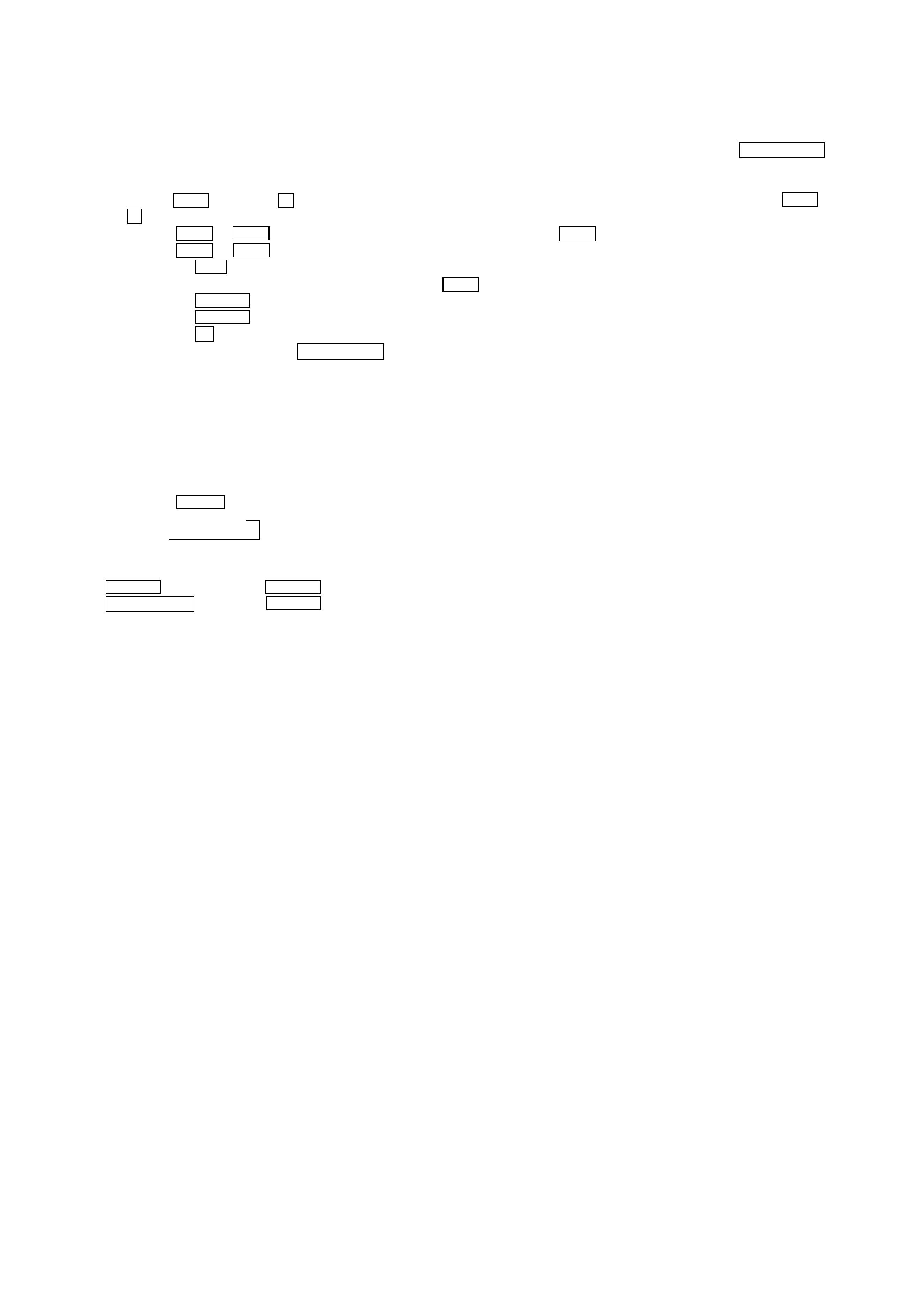
Procedure for using the Self-Diagnosis Function (Error History Display Mode).
Note: Perform the self-diagnosis function in the "error history display mode" in the test mode. The following describes the least required
procedure. Be careful not to enter other modes by mistake. If you set other modes accidentally, press the POWER "X2" button to
exit the mode.
1. Hold the . button and x button down and connect the power plug to the outlet. After a few seconds, release the . button and
x button. When the test mode is set, "[Check]" will be displayed.
2. Press the . or > button and when "[Service]" is displayed, press the 7
button.
3. Press the . or > button and display "Err Display".
4. Pressing the 7 button sets the error history mode and displays "op rec tm".
5. Select the contents to be displayed or executed using the . button.
6. Pressing the POWER button will display or execute the contents selected.
7. Pressing the POWER button another time returns to step 4.
8. Pressing the x button displays "Err Display" and exits the error history mode.
9. To exit the test mode, press the POWER "X2" button. The unit sets into the STANDBY state, the disc is ejected, and the test mode ends.
10.If the unit fails to enter STANDBY mode, remove the AC cord from its socket, insert the AC cord into the socket again, turn on the power,
and then check to make sure that the unit has exited from test mode.
NOTE
· The MDS-LSA1 is designed so that a number of functions which may be performed in test mode may be performed by clicking a single
button.
Switching between functions
Pressing the INPUT button causes the display to change as indicated below.
Hidden t "X2"
The functions performed by each button change in accordance with the DISPLAY mode.
Note that the following notation is used herein:
POWER ............. Press the POWER button when HIDDEN.
POWER "X2" .... Press the POWER button while "X2" is lit.
4
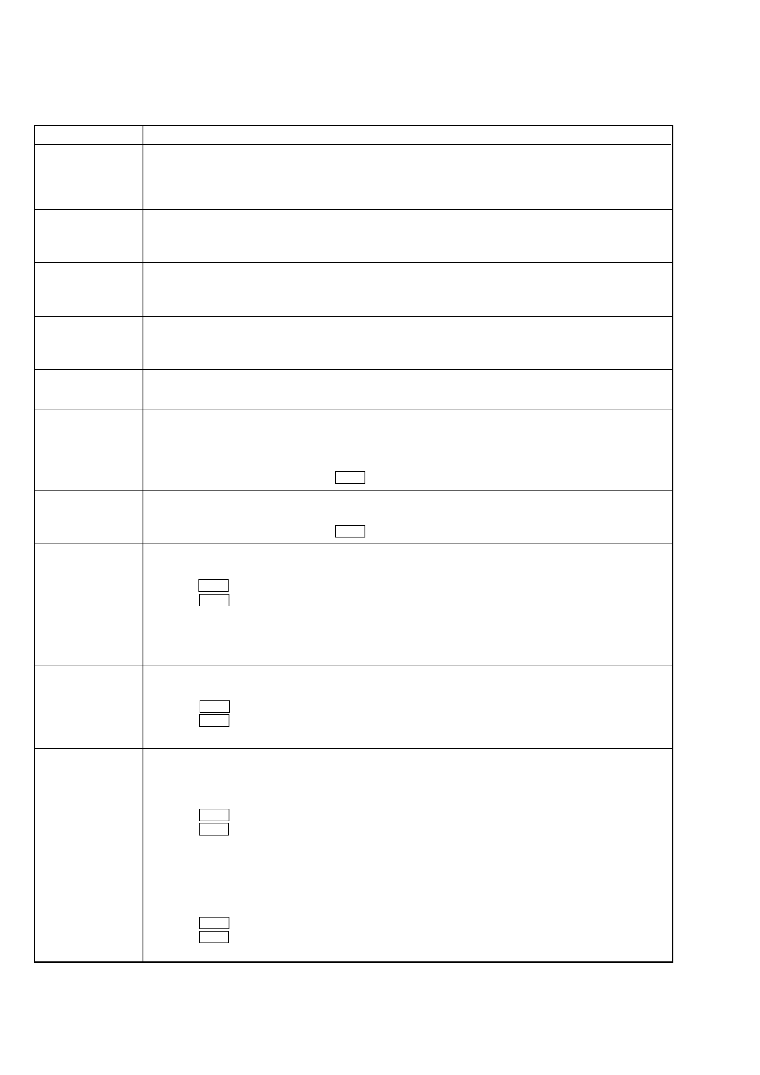
ITEMS OF ERROR HISTORY MODE ITEMS AND CONTENTS
Selecting the Test Mode
Display
op rec tm
op play tm
spdl rp tm
retry err
total err
err history
retry adrs
er refresh
tm refresh
op change
spdl change
History
Displays the total recording time.
When the total recording time is more than 1 minute, displays the hour and minute
When less than 1 minute, displays "Under 1 min"
The display time is the time the laser is set to high power, which is about 1/4 of the actual recording time.
Displays the total playback time.
When the total playback time is more than 1 minute, displays the hour and minute
When less than 1 minute, displays "Under 1 min"
Displays the total rotating time of the spindle motor.
When the total rotating time is more than 1 minute, displays the hour and minute
When less than 1 minute, displays "Under 1 min"
Displays the total number of retry errors during recording and playback
Displays "r xx p yy". xx is the number of errors during recording. yy is the number of errors during playback.
This is displayed in hexadecimal from 00 to FF.
Displays the total number of errors
Displays "total xx". This is displayed in hexadecimal from 00 to FF.
Displays the past ten errors.
Displays "0x ErrCd@@".
X is the history number. The younger the number, the more recent is the history (00 is the latest). @@ is the error
code.
Select the error history number using the . button.
Displays the past five retry addresses.
Displays "xx ADRS yyyy", xx is the history number, yyyy is the cluster with the retry error.
Select the error history number using the . button.
Mode for erasing the error and retry address histories
Procedure
1. Press the . button when displayed as "er refresh".
2. Press the 7
button when the display changes to "er refresh?".
When "complete!" is displayed, it means erasure has completed.
Be sure to check the following after executing this mode.
*Data has been erased.
*Perform recording and playback, and check that the mechanism is normal.
Mode for erasing the total time of recording and playback
Procedure
1. Press the . knob when displayed as "tm refresh".
2. Press the 7
button when the display changes to "tm refresh?".
When "complete!" is displayed, it means erasure has completed.
Mode for erasing the total time of op rec tm, op play tm.
These histories are based on the time of replacement of the optical pick-up. If the optical pick-up has been replaced,
perform this procedure and erase the history.
Procedure
1. Press the . button when displayed as "op change".
2. Press the 7
button when the display changes to "op change?".
When "Complete!" is displayed, it means erasure has completed.
Mode for erasing the total spdl rp tm time
These histories are based on the time of replacement of the spindle motor. If the spindle motor has been replaced,
perform this procedure and erase the history.
Procedure
1. Press the . button when displayed as "spdl change"
2. Press the 7
button when the display changes to "spdl change?"
When "Complete!" is displayed, it means erasure has completed.
5
Description
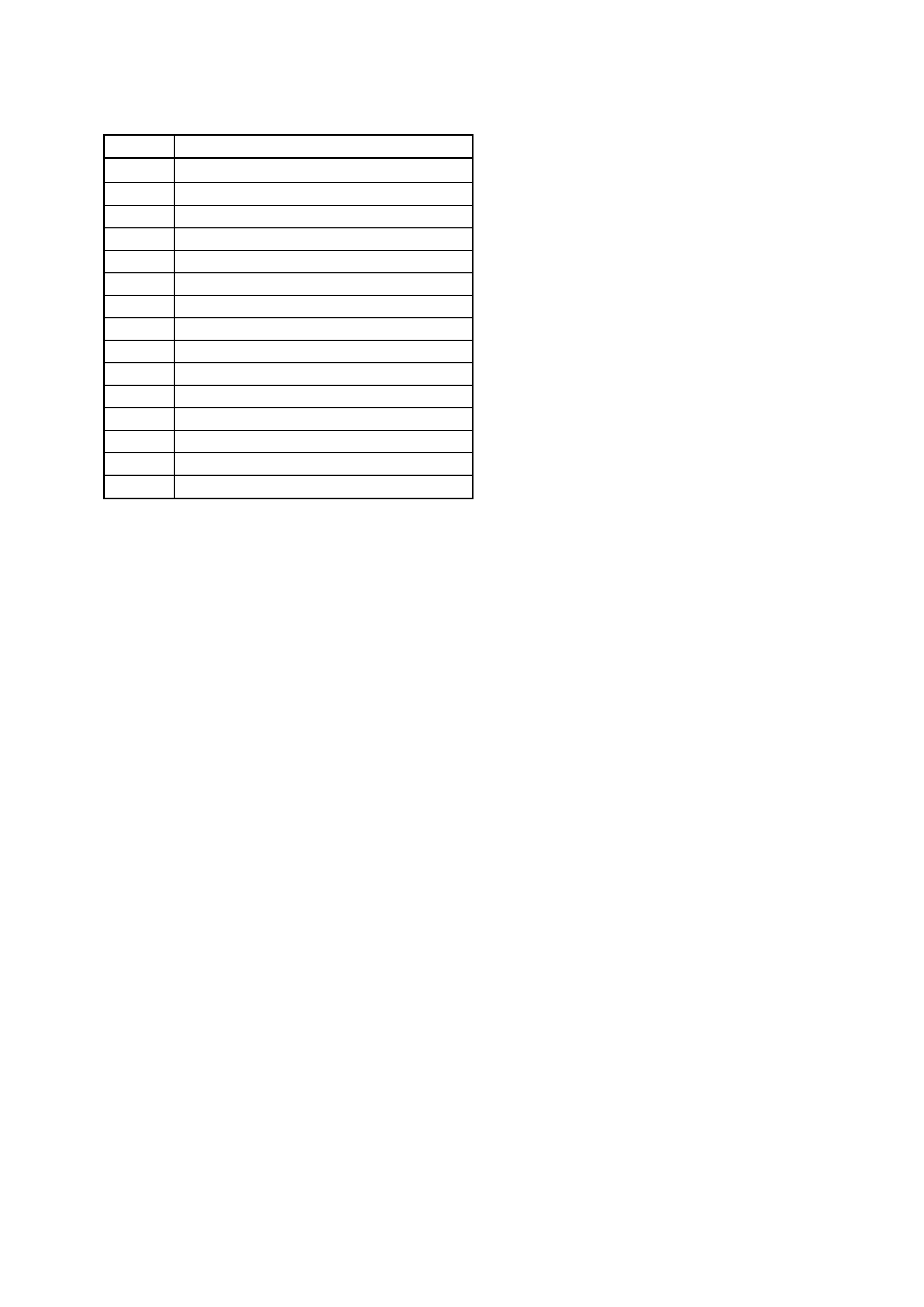
Table of Error Codes
Error Code
10
12
20
21
22
23
24
30
31
40
41
42
43
50
51
Could not load
Loading switches combined incorrectly
Timed out without reading the top of PTOC
Could read top of PTOC, but detected error
Timed out without accessing UTOC
Timed out without reading UTOC
Error in UTOC
Could not start playback
Error in sector
Retry cause generated during normal recording
Retried in DRAM overflow
Retry occurred during TOC writing
Retry aborted during S.F editing
Other than access processing, and could not read address.
Focus NG occurred and overran.
TABLE OF CONTENTS
1. SERVICING NOTES ............................................. 6
2. GENERAL ........................................................................ 12
3. DISASSEMBLY
3-1. Case (Top) ........................................................................... 17
3-2. MD Mechanism Deck ......................................................... 18
3-3. Base (Front) Assy, Panel ..................................................... 18
3-4. Clip Board and Main Board ................................................ 19
3-5. Trans Board ......................................................................... 19
3-6. Holder Assy ......................................................................... 20
3-7. Over Write Head ................................................................. 20
3-8. Optical pick-up (MD) (KMS-262A/J1N) ............................ 21
3-9. BD Board ............................................................................ 21
4. TEST MODE ..................................................................... 22
5. ELECTRICAL ADJUSTMENTS ............................... 30
6. DIAGRAMS
6-1. Circuit Boards Location ...................................................... 41
6-2. Block Diagrams
· BD Section ....................................................................... 42
· Main Section .................................................................... 43
6-3. Printed Wiring Board BD Section ................................. 45
6-4. Schematic Diagram BD Section (1/2) ........................... 46
6-5. Schematic Diagram BD Section (2/2) ........................... 47
6-6. Printed Wiring Board Main Section (Side A) ............... 48
6-7. Printed Wiring Board Main Section (Side B) ............... 49
6-8. Schematic Diagram Main Section (1/3) ........................ 50
6-9. Schematic Diagram Main Section (2/3) ........................ 51
6-10. Schematic Diagram Main Section (3/3) ..................... 52
6-11. Printed Wiring Board Power Section ......................... 53
6-12. Printed Wiring Board Panel Section ........................... 54
6-13. Schematic Diagram Panel Section ............................. 55
6-14. IC Block Diagrams ........................................................... 56
6-15. IC Pin Functions ............................................................... 59
7. EXPLODED VIEWS
7-1. Panel Section ....................................................................... 70
7-2. Chassis Section ................................................................... 71
7-3. MD Mechanism Section-1 (MDM-7X2B) .......................... 72
7-4. MD Mechanism Section-2 (MDM-7X2B) .......................... 73
8. ELECTRICAL PARTS LIST ........................................ 74