-- 1 --
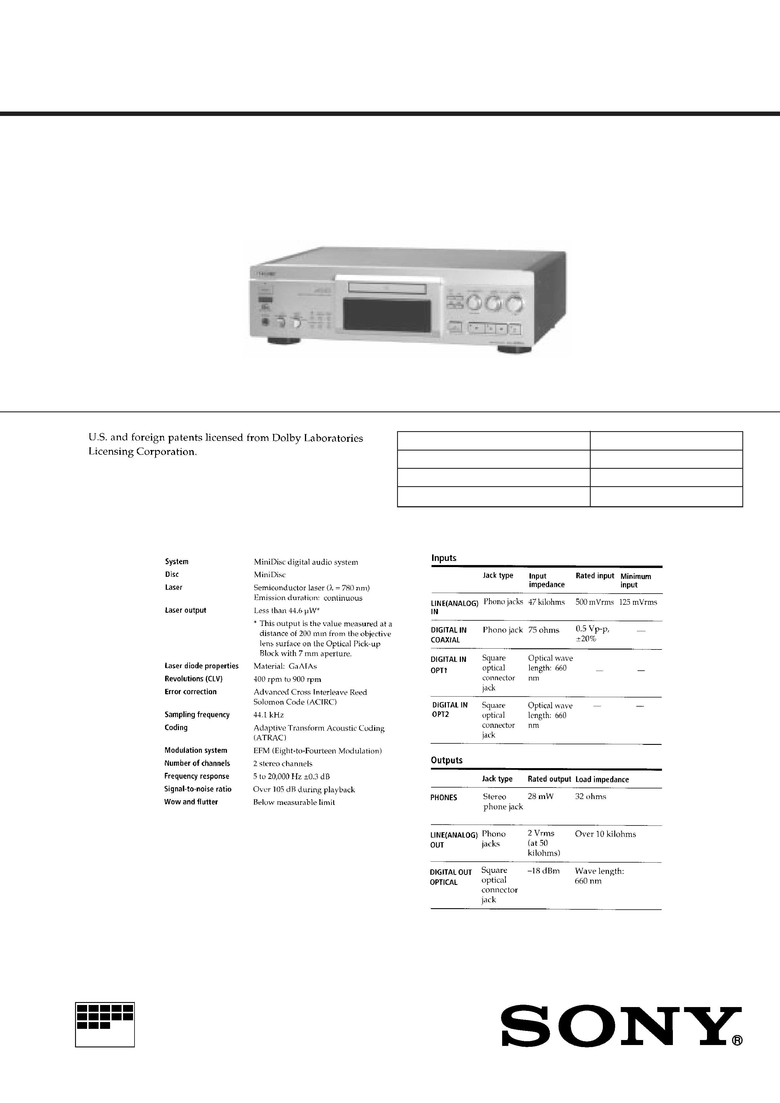
SPECIFICATIONS
Model Name Using Similar Mechanism
NEW
MD Mechanism Type
MDM-4A
Base Unit Type
MBU-2B
Optical Pick-up Type
KMS-210A/J-N
MDS-JA50ES
SERVICE MANUAL
US Model
AEP Model
UK Model
MINIDISC DECK
MICROFILM
Photo: GOLD
MC-Service
-- 2 --
CAUTION
Danger of explosion if battery is incorrectly replaced.
Replace only with the same or equivalent type recommended by
the equipment manufacturer.
Discard used batteries according to manufacture's instructions.
ADVARSEL!
Lithiumbatteri - Eksplosionsfare ved fejlagtig håndtering.
Udskiftning må kun ske med batteri af samme fabrikat og type.
Levér det brugte batteri tilbage til leverandøren.
ADVARSEL
Eksplosjonsfare ved feilakting skifte av batteri.
Benytt samme batteritype eller en tilsvarende type anbefalt av
apparatfabrikanten.
Brukte batterier katterier kasseres i henhold til fabrikantens
VARNIG
Explosionsfara vid felaktigt batteribyte.
Använd samma batterityp eller en likvärdig typ som rekommenderas
av apparattillverkaren.
Kassera använt batteri enligt gällande föreakrifter.
VAROITUS
Parist voi räjähtää, jos se on virheellisesti asennettu.
Vaihda paristo ainoastaan laitevalmistajan suosittelemaan tyyppiin.
Hävitä käytetty paristo valmistajan ohjeiden mukaisesti.
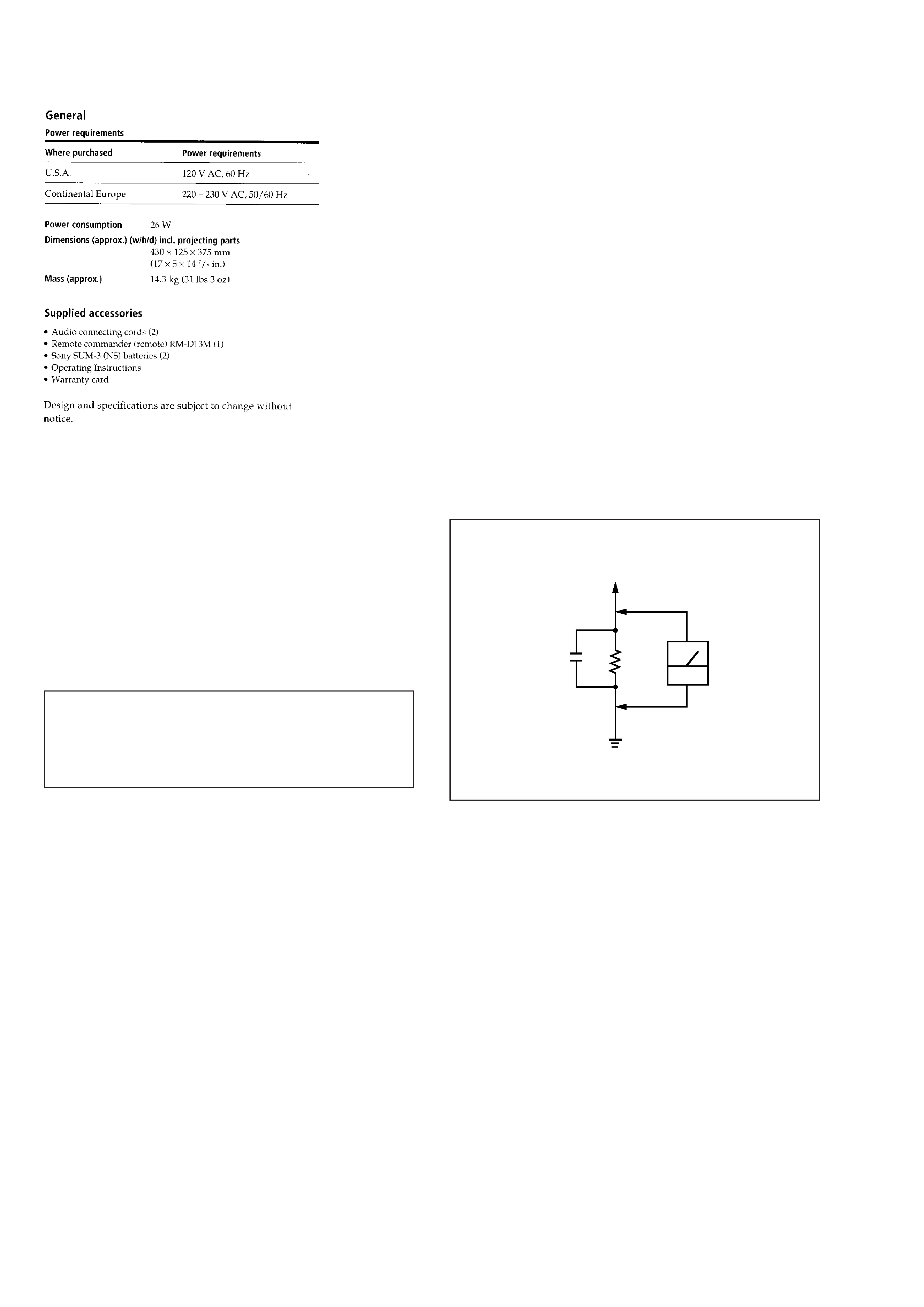
To Exposed Metal
Parts on Set
0.15µF
1.5k
AC
voltmeter
(0.75V)
Earth Ground
SAFETY CHECK-OUT
After correcting the original service problem, perform the follow-
ing safety checks before releasing the set to the customer:
Check the antenna terminals, metal trim, "metallized" knobs, screws,
and all other exposed metal parts for AC leakage. Check leakage as
described below.
LEAKAGE
The AC leakage from any exposed metal part to earth Ground and
from all exposed metal parts to any exposed metal part having a
return to chassis, must not exceed 0.5 mA (500 microampers). Leak-
age current can be measured by any one of three methods.
1. A commercial leakage tester, such as the Simpson 229 or RCA
WT-540A. Follow the manufacturers' instructions to use these
instruments.
2. A battery-operated AC milliammeter. The Data Precision 245
digital multimeter is suitable for this job.
3. Measuring the voltage drop across a resistor by means of a VOM
or battery-operated AC voltmeter. The "limit" indication is 0.75
V, so analog meters must have an accurate low-voltage scale.
The Simpson 250 and Sanwa SH-63Trd are examples of a pas-
sive VOM that is suitable. Nearly all battery operated digital
multimeters that have a 2V AC range are suitable. (See Fig. A)
Fig. A. Using an AC voltmeter to check AC leakage.
SAFETY-RELATED COMPONENT WARNING !!
COMPONENTS IDENTIFIED BY MARK
! OR DOTTED LINE
WITH MARK
! ON THE SCHEMATIC DIAGRAMS AND IN
THE PARTS LIST ARE CRITICAL TO SAFE OPERATION.
REPLACE THESE COMPONENTS WITH SONY PARTS
WHOSE PART NUMBERS APPEAR AS SHOWN IN THIS
MANUAL OR IN SUPPLEMENTS PUBLISHED BY SONY.
-- 3 --
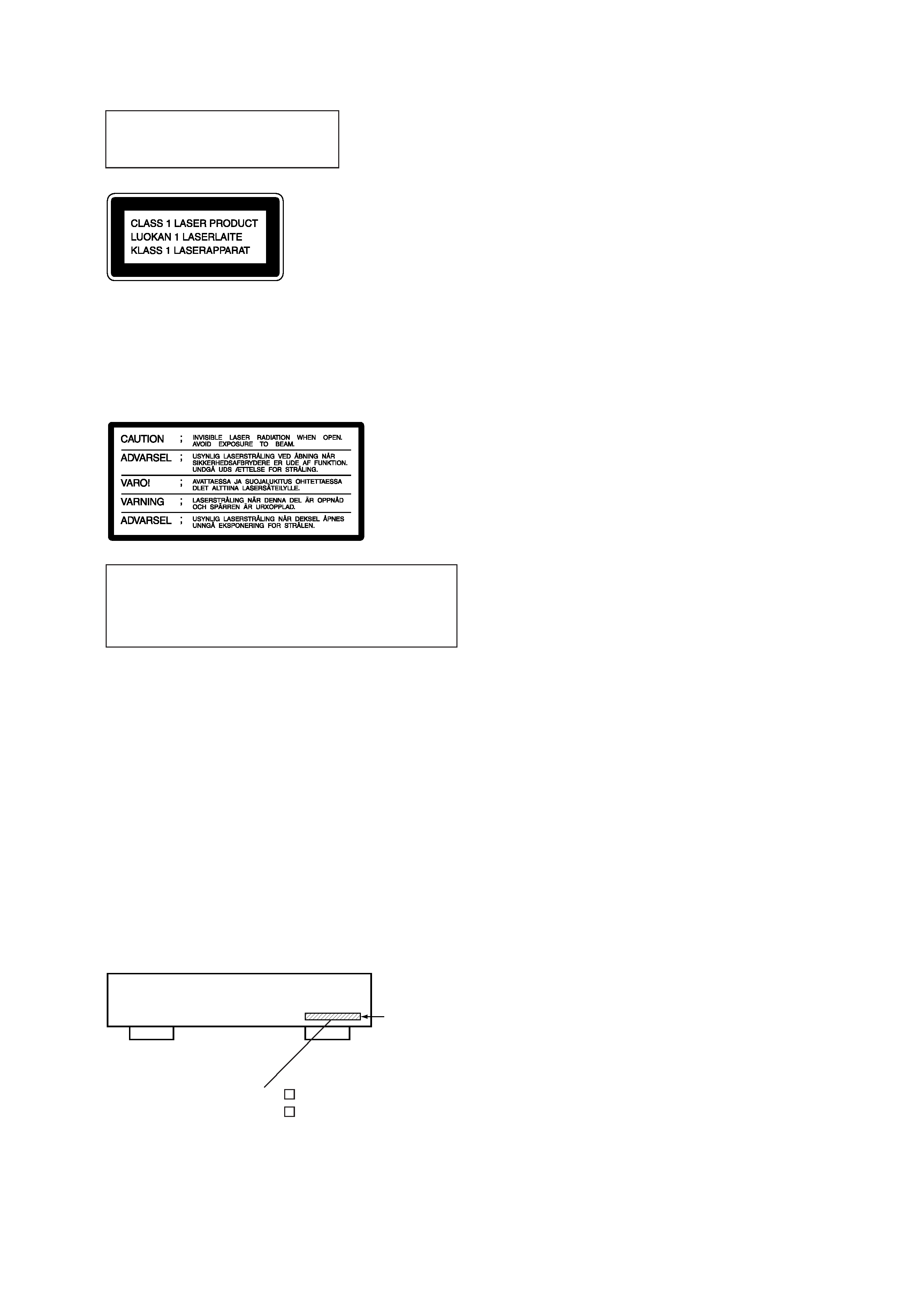
This appliance is classified as a CLASS 1
LASER product. The CLASS 1 LASER
PRODUCT MARKING is located on the
rear exterior.
The following caution label is located
inside the unit.
CAUTION
Use of controls or adjustments or performance of procedures
other than those specified herein may result in hazardous ra-
diation exposure.
Notes on chip component replacement
· Never reuse a disconnected chip component.
· Notice that the minus side of a tantalum capacitor may be
damaged by heat.
Flexible Circuit Board Repairing
· Keep the temperature of soldering iron around 270°C
during repairing.
· Do not touch the soldering iron on the same conductor of the
circuit board (within 3 times).
· Be careful not to apply force on the conductor when soldering
or unsoldering.
The laser component in this product is
capable of emitting radiation exceeding
the limit for Class 1.
MODEL IDENTIFICATION
-- BACK PANEL --
Parts No.
4-987-511-2
: AEP, UK, German model
4-987-511-3
: US model
TABLE OF CONTENTS
1. SERVICING NOTE .......................................................... 4
2. GENERAL .......................................................................... 7
3. DISASSEMBLY
3-1. Tray Assembly .................................................................... 26
3-2. Bracket (Motor) ASSY ....................................................... 27
3-3. Holder ASSY ...................................................................... 27
3-4. Base Unit ............................................................................. 28
3-5. HMOT Board and HLIM Board ......................................... 28
4. TEST MODE ..................................................................... 29
5. ELECTRICAL ADJUSTMENTS ............................... 32
6. DIAGRAMS
6-1. Brock Diagrams
· BD Section ....................................................................... 37
· Digital Section ................................................................. 39
· Audio Section .................................................................. 41
· Power Section .................................................................. 43
6-2. Circuit Boards Location ...................................................... 44
6-3. Waveforms ......................................................................... 45
6-4. Printed Wiring Board -- BD Section -- ............................. 47
6-5. Schematic Diagram -- BD Section -- ............................... 49
6-6. Schematic Diagram -- Digital Section -- .......................... 52
6-7. Printed Wiring Board -- Digital Section -- ....................... 55
6-8. Printed Wiring Board -- MD Section -- ............................ 57
6-9. Schematic Diagram -- MD Section -- .............................. 58
6-10. Printed Wiring Board -- D Out, D Vol Section -- .......... 59
6-11. Schematic Diagram -- D Out, D Vol Section -- ............. 60
6-12. Printed Wiring Board -- DA Section -- .......................... 61
6-13. Schematic Diagram -- DA Section -- ............................. 63
6-14. Printed Wiring Board -- AD Section -- .......................... 65
6-15. Schematic Diagram -- AD Section -- ............................. 67
6-16. Printed Wiring Board -- Panel Section -- ....................... 69
6-17. Schematic Diagram -- Panal Section -- ......................... 71
6-18. Printed Wiring Board -- Power Section -- ..................... 73
6-19. Schematic Diagram -- Power Section -- ........................ 75
6-20. IC Block Diagrams ........................................................... 77
6-21. IC Pin Functions ............................................................... 84
7. EXPLODED VIEWS
7-1. Main Section ..................................................................... 100
7-2. Chassis Section ................................................................. 101
7-3. Front Panel Section 1 ........................................................ 102
7-4. Front Panel Section 2 ........................................................ 103
7-5. Mechanism Section 1 (MDM-4A) .................................... 104
7-6. Mechanism Section 2 (MDM-4A) .................................... 105
7-7. Mechanism Section 3 (MDM-4A) .................................... 106
7-8. Base Unit Section (MBU-2B) ........................................... 107
8. ELECTRICAL PARTS LIST ...................................... 108
MC-Service
-- 4 --
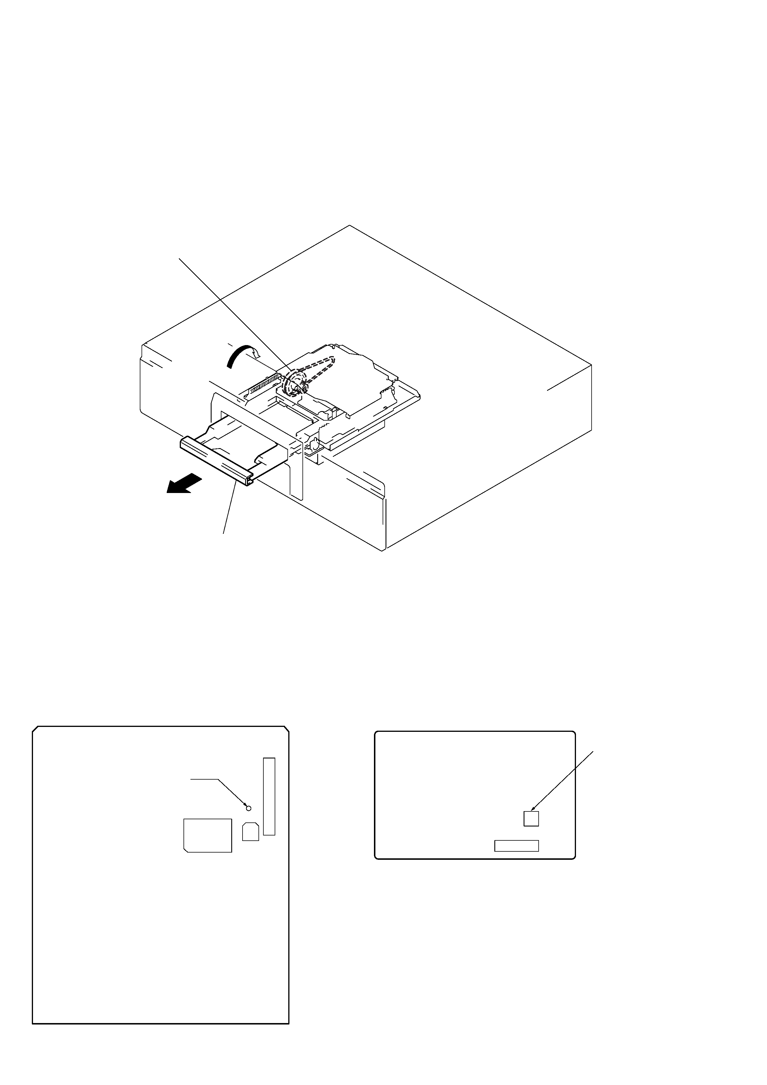
SECTION 1
SERVICING NOTE
HOW TO OPEN THE DISC TRAY WHEN POWER SWITCH TURNS OFF
1 Remove the fourteen screws (BVTT 3x8) from the bottom plate.
2 Remove the bottom plate.
3 Rotate the pulley gear in the arrow direction A, and open the tray assembly in the arrow direction B.
Pully gear
A
B
Tray assembly
FORCED RESET
The system microprocessor can be reset in the following way.
Use these methods when the unit cannot be operated normally due to the overrunning of the microprocessor, etc.
Method 2:
Disconnect the power plug, and short-circuit CN905 of the PW board
with a pair of tweezers, etc.
[PW board] (Component Side)
CN905
(RESET)
CN901
Method 1:
Set TP (S.RST) of the DIG board to ground momentarily.
[DIG board] (Side A)
TP
(S.RST)
CN203
C206
IC202

-- 5 --
RETRY CAUSE DISPLAY MODE
· In this test mode, the causes for retry of the unit during recording can be displayed on the fluorescent display tube.
This is useful for locating the faulty part of the unit.
· The retry cause, number of retries, and number of retry errors are displayed. Each is displayed in hexadecimal number.
Method:
1. Load a recordable disc whose contents can be erased into the unit.
2. Press the
p button, §OPEN/CLOSE button, DISPLAY/CHAR button simultaneously.
3. Press the
r button, and start recording.
4. The ## value increases with each retry. If an error occurs after a retry, the @@ count will also increase.
5. To exit the test mode, press the TIME button.
Fig. 1 Reading the Test Mode Display
R.T s
c # # e @@
Fluorescent Display Tube Signs
: Cause of retry
# # : Number of retries
@@ : Number of retry errors
All three displays above are in hexadecimal numbers.