MDR-RF415R
AEP Model
SERVICE MANUAL
HEADPHONES
Sony Corporation
Audio Entertainment Group
General Engineering Dept.
9-873-075-11
2001B1600-1
© 2001.2
SPECIFICATIONS
Ver 1.0 2001. 02
Headphones
MDR-RF415R
Transmitter
TMR-RF415R
MDR-RF415R is the component model block one in the MDR-RF415RK.
COMPONENT MODEL NAME FOR MDR-RF415RK
Power source
DC 2.4 V: Built-in rechargeable battery
Mass
Approx. 240 g (8.5 oz.) incl.
built-in rechargeable battery
Built-in Ni-Cd rechargeable battery
Model name
NC-AA
Voltage
1.2 V
Capacity
700 mAh
Design and specifications are subject to change without notice.
2
MDR-RF415R
SECTION 1
GENERAL
This section is extracted
from instruction manual.
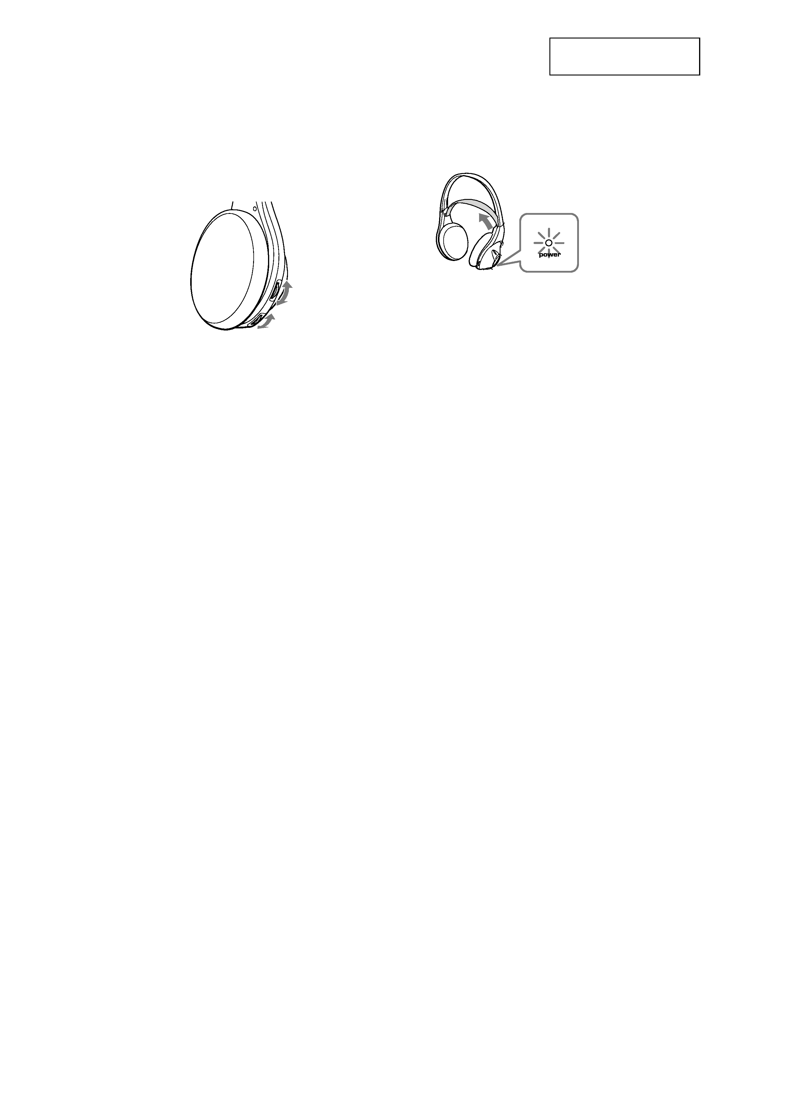
5 Turn up the volume to a moderate level
with the VOL control, then tune the
headphones in to the frequency of the
transmitter with the TUNING control
until you can hear the audio signal
loud and clear.
TUNING
control
VOL control
Auto power on/off function
When you remove the headphones from your
head, the power turns off automatically. Do not
allow the self adjusting band to be pulled up,
otherwise the headphones will be switched on.
The power turns on.
Notes on chip component replacement
· Never reuse a disconnected chip component.
· Notice that the minus side of a tantalum capacitor may be
damaged by heat.
3
MDR-RF415R
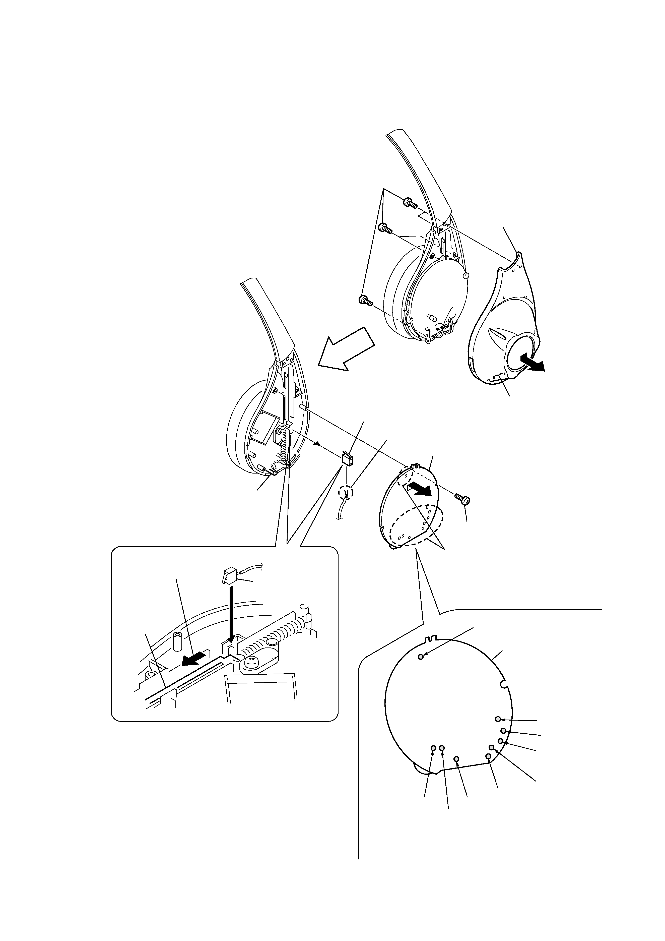
SECTION 2
DISASSEMBLY
2-1. RX-BASE BOARD
Note : Follow the disassembly procedure in the numerical order given.
3
Remove the
nine solderings.
8
Remove the two solderings.
RX-BASE board
Solder the each lead wires directly to the position as shown
while being cautions of colors.
Precaution for installtion
Precaution for installtion
6
RX-BASE board
9
Switch, push (1 key)
Cover (R), hanger
No.203
No.203 (black)
No.202 (red)
No.201 (green)
No.201
No.204
No.205
No.204
No.202
4
Screw (P 2
× 8)
1
Five screws (P 2
× 6)
2
Set the push
switch (1 key).
Suspender
1
Slide the suspender in the
direction of the arrow.
Claw
Claw
2
5
7
4
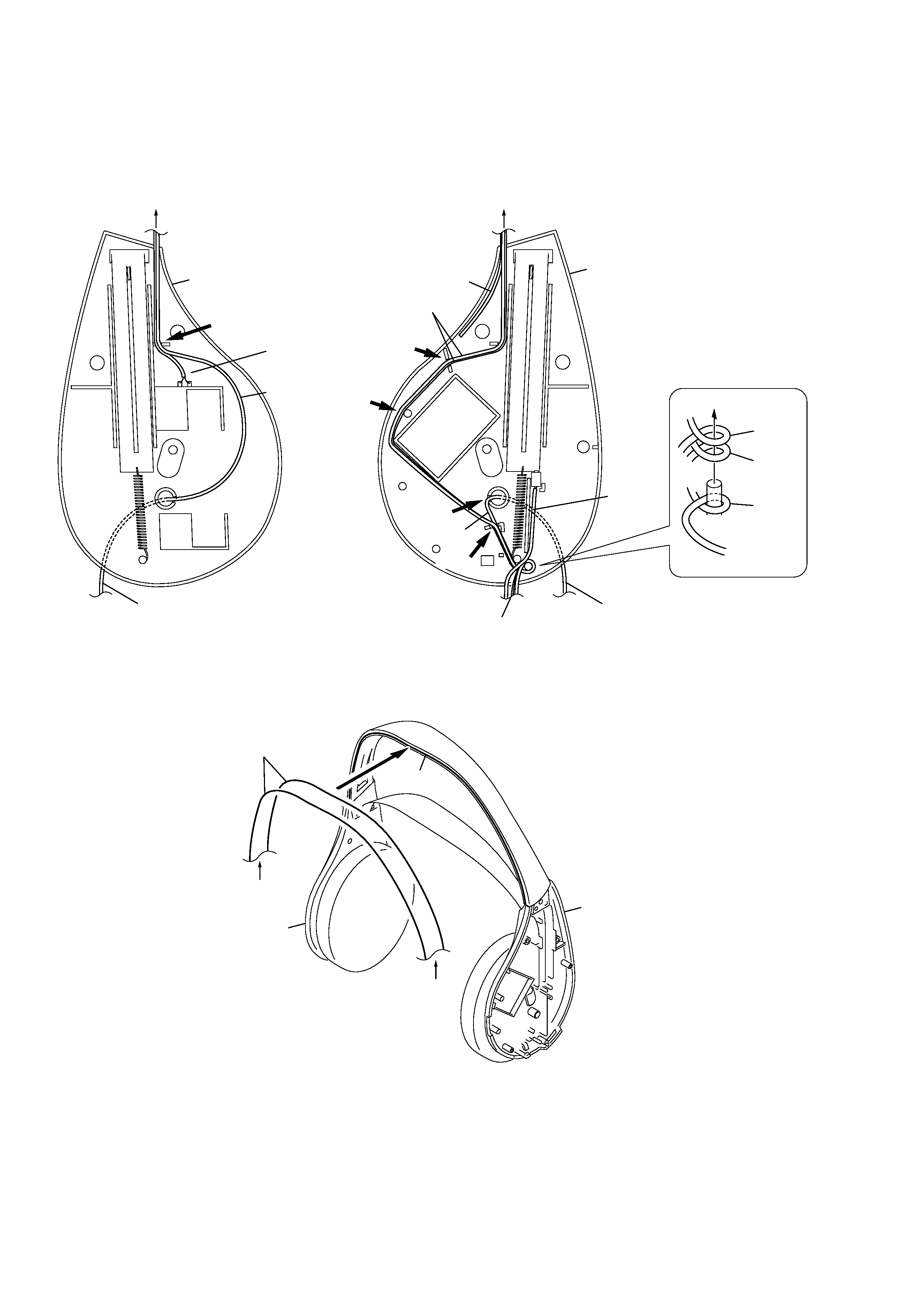
MDR-RF415R
No.201
Cover (L), hanger
Cover (L), hanger
No.203
No.201, No.203
No.201, No.203
Groove
Set the lead wires
No.204
No.205
No.202
No.202
No.201
No.203
Set the each lead wires as illustrated below.
Cover (R), hanger
A
B
Cover (R), hanger
Groove
Groove
Groove
Groove
To the driver (030F032//K).
To the RX-BASE board
Groove
To the driver (030F032//K).
B
A

5
MDR-RF415R
SECTION 3
ELECTRICAL ADJUSTMENTS
Notes:
1.
Use transmitter with check and adjustment already completed.
2.
On adjusting the headphones section, use the transmitter as a
jig.
Headphones:MDR-RF415R
Transmitter:TMR-RF415R
Procedure:
1.
Connect an oscillator with attenuator and terminator (600
)
to the transmitter AUDIO IN-A connector (J402).
2.
Connect an AC adapter to the transmitter DC IN 9V jack (J404).
3.
Connect lead wires to IC301 pin 4, pin 6, pin 7 and GND on
the RX-BASE board.
4.
Connect a resistor 33k
between IC301 pin 4 and pin 7.
5.
Connect lead wires to the speakers' terminals (L+,L-,R+,R-)
on the RX-BASE board.
3-1. Free run frequency check and adjustment
1.
Set the transmitter AUDIO IN-A connector (J402) to no signal.
Note: In this case, operation time is about 4 or 5 minutes.
2.
Check the transmitter power indicator (red) lights.
3.
Set the transmitter CHANNEL switch to 1.
4.
Set the headphones tuning (RV303) to center position.
5.
Connect a frequency counter to IC301 pin 4 and GND on the
RX-BASE board.
6.
Adjust the value of the frequency counter to specification by
RV301 on the RX-BASE board.
Specified Values: 76kHz
± 50Hz.
3-2. Receive frequency check and adjustment
1.
Set the transmitter CHANNEL switch to 2.
2.
Set the transmitter NOISE FILTER switch to OFF.
3.
Input a signal of 1kHz, 316mVrms to transmitter
AUDIO IN-A-L connector only.
4.
Keep distance transmitter and headphones to 5 meters over.
5.
Set the headphones volume (RV302) to minimum.
6.
Set the headphones tuning (RV303) to center position.
7.
Connect an oscilloscope CH1 and CH2 to IC301 pin 6 and pin 4.
8.
Check the waveform of the oscilloscope to CH1 is demodulated
1kHz signal and CH2 is GND.
9.
If CH1 and CH2 are not satisfied step 8, adjust the coil (L301)
on the RX-BASE board to satisfied step 8.
10. Set the transmitter CHANNEL switch to 1 or 3.
11. Adjust the headphones tuning (RV303) to receive radio
frequency.
12. Check same step 8.
3-3. Carrier modulation check
1.
Set the transmitter CHANNEL switch to 2.
2.
Set the transmitter NOISE FILTER switch to OFF.
3.
Input a signal of 1kHz, 316mVrms to transmitter
AUDIO IN-A-L connector only.
4.
Adjust the headphones tuning (RV303) to receive radio
freqency.
5.
Set the headphones volume (RV302) to minimum.
6.
Connect an oscilloscope CH1 and CH2 to IC301 pin 6 and pin 4.
7.
Check the waveform of the oscilloscope to CH1 is demodulated
1kHz signal and CH2 is GND.
8.
Connect an AC volt meter to IC301 pin 6 and GND.
9.
Check the value of the AC volt meter to 26mVrms
± 2mV
3-4. Separation check
1.
Set the transmitter CHANNEL switch to 2.
2.
Set the transmitter NOISE FILTER switch to OFF.
3.
Input a signal of 1kHz, 316mVrms to transmitter
AUDIO IN-A-L connector only.
4.
Adjust the headphones tuning (RV303) to receive radio
freqency.
5.
Connect an oscilloscope to CH1 is demodulated 1kHz signal
and CH2 is GND.
6.
Check the waveform of the oscilloscope to CH1 is demodulated
1kHz signal and CH2 is GND.
7.
Connect an AC volt meter with LPF to speakers terminal (L+,L-).
8.
Adjust the value of the AC volt meter to specification by
headphones volume (RV302).
Specified Value: 155mVrms
9.
Connect an AC volt meter with LPF to speakers terminal (R+,R-).
10. Measure the value of the AC volt meter.
11. Check the difference of the L and R to more than 20dB.
12. Input a signal of 1kHz, 316mVrms to transmitter
AUDIO IN-A-R connector only.
13. Connect an AC volt meter to speakers terminal (R+,R-).
14. Adjust the value of the AC volt meter to specification by
headphones volume (RV302).
Specified Value: 155mVrms
15. Connect an AC volt meter to speakers terminal (L+,L-).
16. Measure the value of the AC volt meter.
17. Check the difference of the L and R to more than 20dB.
Adjustment Location : (See page 6)