MDR-IF630R
US Model
AEP Model
UK Model
E Model
Tourist Model
SERVICE MANUAL
HEADPHONES
Headphones
MDR-IF630R
Transmitter
TMR-IF630R
MDR-IF630R is the component model block one in the MDR-IF630RK.
COMPONENT MODEL NAME FOR MDR-IF630RK
SPECIFICATIONS
Built-in rechargeable batteries
Model name
NH-AAC
Type
Ni-MH
Voltage
1.2 V
Capacity
1000 mAh
Headphones
Type
Closed, dynamic
Driver unit
30 mm dia. with neodymium
magnet
Frequency response
12 24,000 Hz
Power source
DC 2.4 V: Built-in rechargeable
batteries
Mass
Approx. 310 g (10.9 oz)
Design and specifications are subject to change without
notice.
Ver 1.0 2000. 12
-- 2 --
SECTION 1
GENERAL
This section is extracted
from instruction manual.
Notes on chip component replacement
· Never reuse a disconnected chip component.
· Notice that the minus side of a tantalum capacitor may be
damaged by heat.
Flexible Circuit Board Repairing
· Keep the temperature of soldering iron around 270°C
during repairing.
· Do not touch the soldering iron on the same conductor of the
circuit board (within 3 times).
· Be careful not to apply force on the conductor when soldering
or unsoldering.
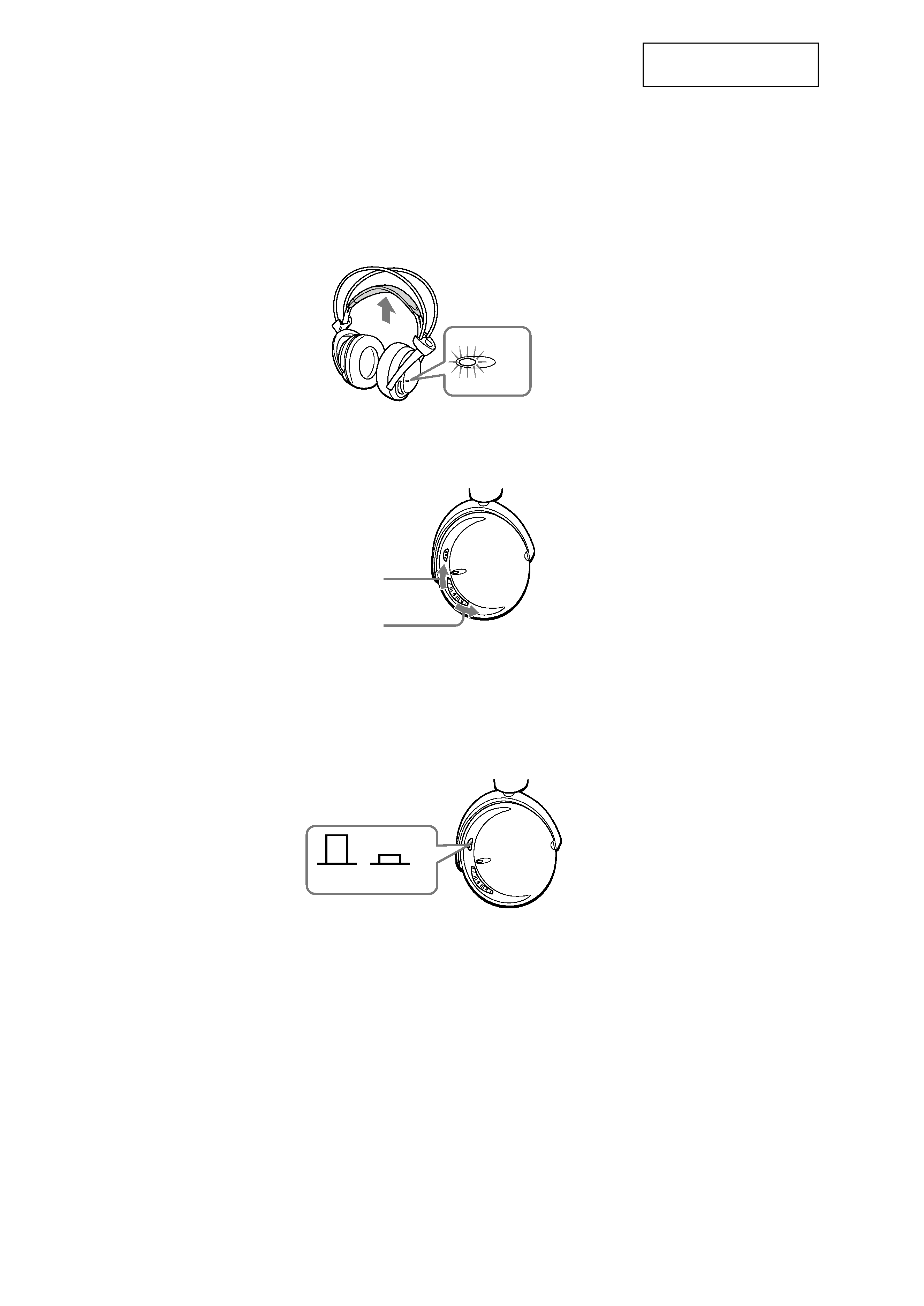
Check the remaining power of the
headphone batteries
Pull up the suspender, and check that the
headphones' power indicator lights in red. You
can now use the headphones.
Charge the batteries or install new batteries, if the
power indicator light is weak or turned off and
the sound become distorted or has a lot of noise.
POWER
3 Adjust the volume.
High
Low
Audio mode switch
Depress the audio mode switch (VOICE mode) to
emphasize the human voice. Press to release it
(NORMAL mode) for normal tone quality.
Audio mode switch
NORMAL
VOICE
-- 3 --
SECTION 2
DISASSEMBLY
2-2. RX BASE BOARD
Note :
Follow the disassembly procedure in the numerical order given.
· The equipment can be removed using the following procedure.
Driver (R side)
RX BASE board
Driver (L side)
RX CHR board
Set
Lid (R), holder
Hanger (R)
RX SW board, Holder (R)
Lid (L), holder
Hanger (L)
Holder (L)
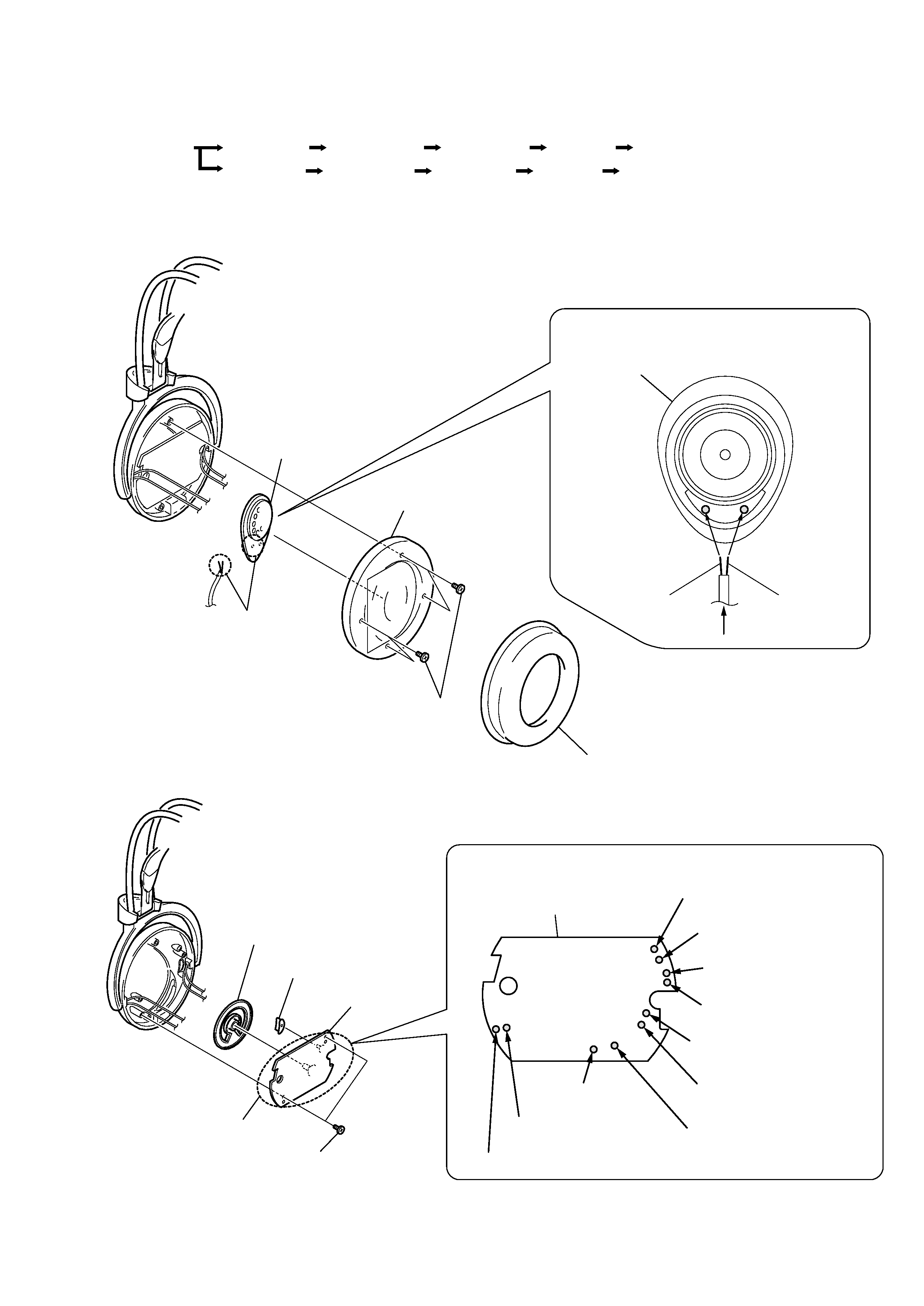
2-1. DRIVER (R SIDE)
Driver (R side)
Driver (R side)
From RX BASE board
2
Four screws
(+P2
× 6)
Solder the each lead wires
directly to the position as
shown while being
cautions of colors
Precaution for installation
1
Pad, ear
3
Plate (R) assy, front
4
Remove the two solderings
Natural
Red
from RX SW board () (natural)
Head band (rear) (natural)
Driver (natural)
Driver (red)
Head band (front) (green)
Head band (front) (natural)
Head band (front) (natural)
Head band (front) (black)
Head band (rear) (red)
from RX SW board (+) (black)
RX BASE board
RX BASE board
3
Button, sound selection
4
Knob, volume
1
Two screws (+P2
× 6)
2
Remove the ten solderings
Solder the each lead wires directly to the position as
shown while being cautions of colors
Precaution for installation
-- 4 --
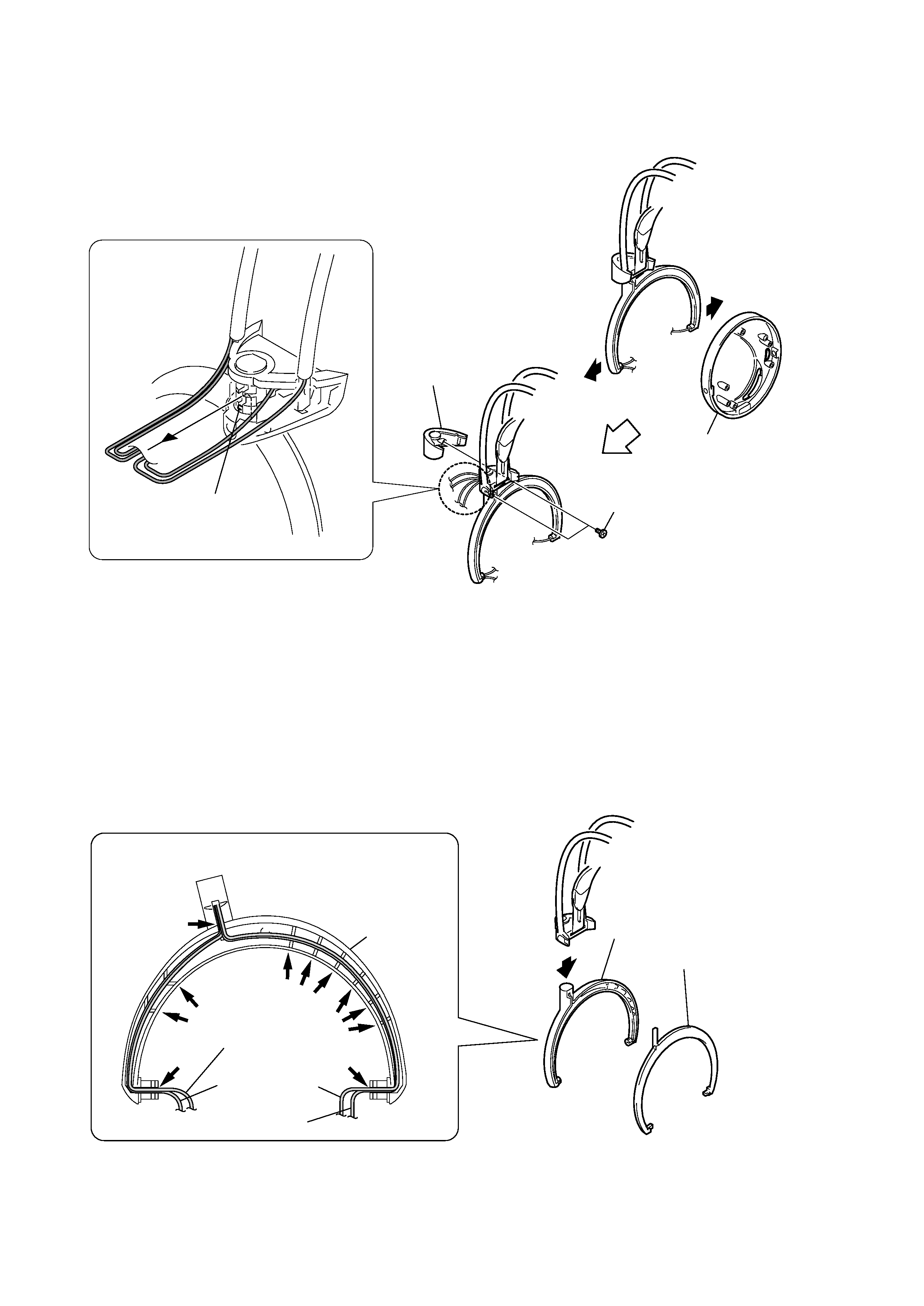
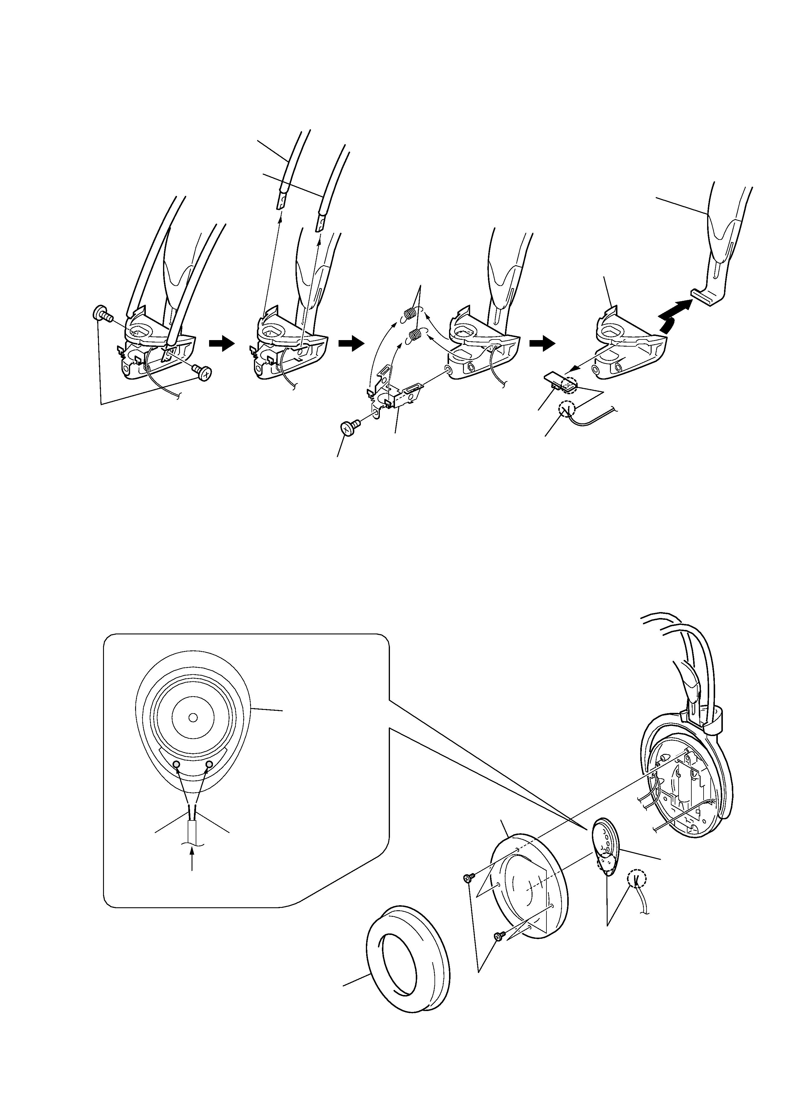
2-3. LID (R), HOLDER
2-4. HANGER (R)
2
Housing (R) assy
6
Claw
1
1
5
4
Lid (R), holder
3
Two screws (+P2
× 6)
2 Lid (R) hanger
Hanger (R)
HANGER (R)
Groove
Groove
Groove
Groove
Groove
Groove
From head band (rear)
From RX SW board
From head band
(front)
1
Solder the each lead wires directly to the position as
shown while being cautions of colors
Precaution for installation
-- 5 --
2-5. RX SW BOARD, HOLDER (R)
2-6. DRIVER (L SIDE)
Holder (R)
Natural
RX SW board
8
Remove the two solderings
q;
Cushion assy, head
9
1
Two screws (+P2
× 2.5)
2
Head band (front)
3
Head band (rear)
5
Chassis
4
Screw (+P2
× 5)
6
Two springs
7
Driver (L side)
Driver (L side)
From head band (rear)
Natural
Green
2
Four screws (P2
× 6)
1
Pad, ear
3
Plate (L) assy, front
4
Remove the two solderings
Solder the each lead wires
directly to the position as
shown while being
cautions of colors
Precaution for installation