Ver 1.1 2000. 06
Headphone
Charging and using hours (MDR-IF330R)
Approx. charging hours
Approx. using hours*
1
1.5
24**
30
*
at 1kHz 1mW + 1mW output
** the hours required to fully charge an cmpty battery
Battery life* (MDR-IF230/IF330R)
Battery
Approx. hours
Sony alkaline battery LR6(SG)
100
Sony battery R6P(SR)
50
*
at 1kHz 1mW + 1mW output
Power source
Supplied Ni-Cd rechargeable battery NC-AA(HJ)
or commercially available R6 (size AA) dry battery
Mass
Approx. 180g (6.4oz.) including battery
Supplied Ni-Cd rechargeable battery
Model name
NC-AA (HJ)
Type
Ni-Cd
Voltage
1.2V
Capacity
600mAh
Design and specifications are subject to change without notice.
MICROFILM
MDR-IF230/IF330R
SERVICE MANUAL
CORDLESS STEREO HEADPHONES
US Model
Canadian Model
E Model
Australian Model
MDR-IF230/IF330R
Tourist Model
MDR-IF330R
MDR-IF130K
MDR-IF230RK MDR-IF330RK
Cordless Headphones
MDR-IF230
MDR-IF230
MDR-IF330R
Transmitter
TMR-IF130
TMR-IF230R
TMR-IF330R
COMPONENT MODEL NAME FOR MDR-IF130K/IF230RK/IF330RK
SPECIFICATIONS
MDR-IF230 is the component model block one in the MDR-IF130K
or MDR-IF230RK.
MDR-IF330R is the component model block one in the MDR-IF330RK.
Illustration : MDR-IF330R
2
SECTION 1
DISASSEMBLY
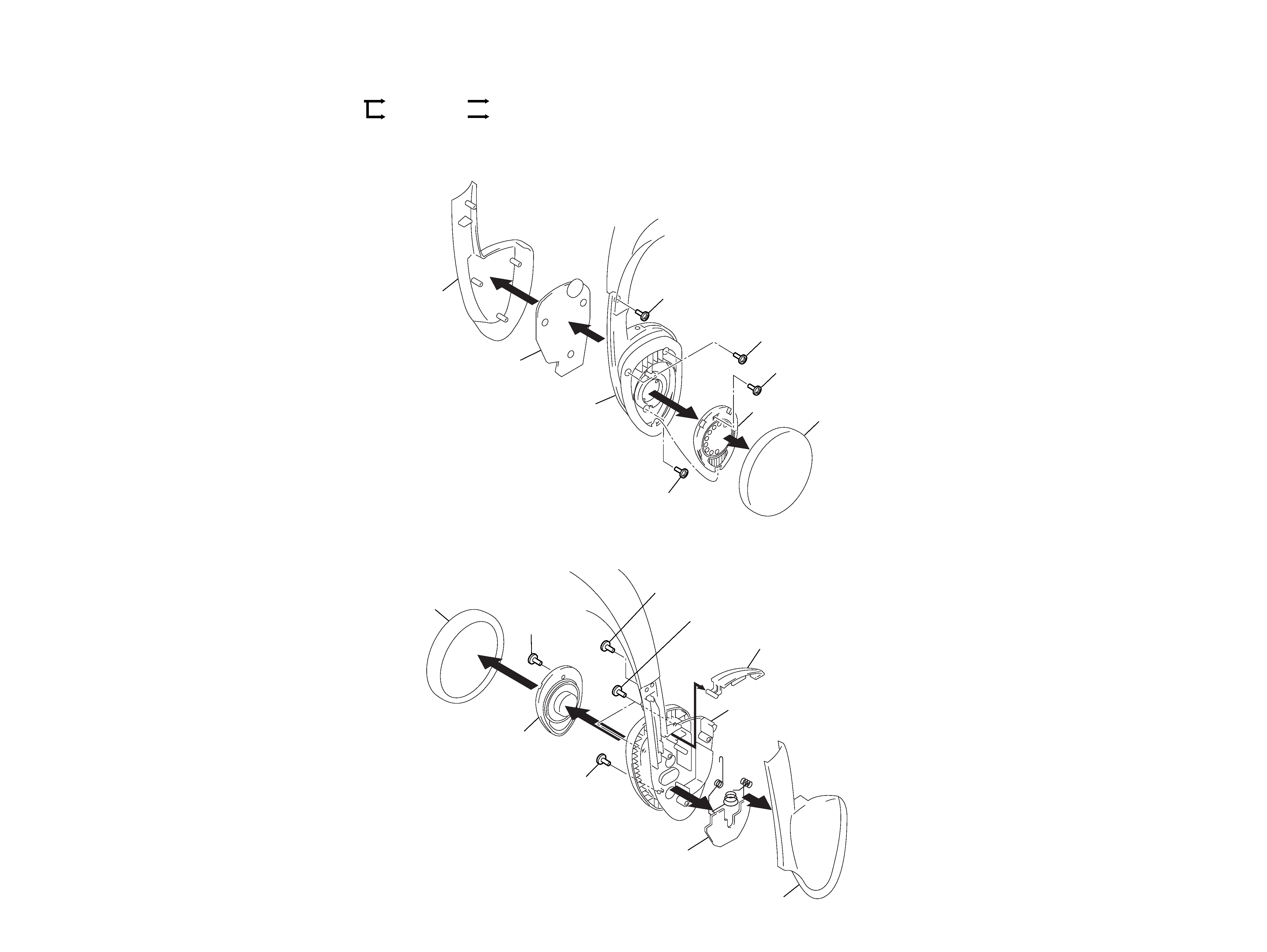
Note:Followthedisassemblyprocedureinthenumericalordergiven.
1-1. RX BOARD REMOVAL
1-2. PD BOARD REMOVAL
5 Screw +P (2x6)
4 Screws +P (2x6)
2 Screw (M 1.7x4)
4 Screw +P (2x6)
Cover (R), hanger
RX board
Hanger (R)
SP2
Pat, ear
7
6
3
1
4 Screw +P (2x6)
4 Screws +P (2x6)
2 Screw
(M 1.7x4)
5 Screw +P (2x6)
Cover (L), hanger
PD board
Hanger (L)
Lid, battery case
SP1
Pat, ear
7
3
8
6
1
r
Theequipmentcanberemo
vedusingthef
ollo wingpr ocedure .
Set
Cover (R), hanger
RX board
Cover (L), hanger
PD board
3
4
TMR-IF330R
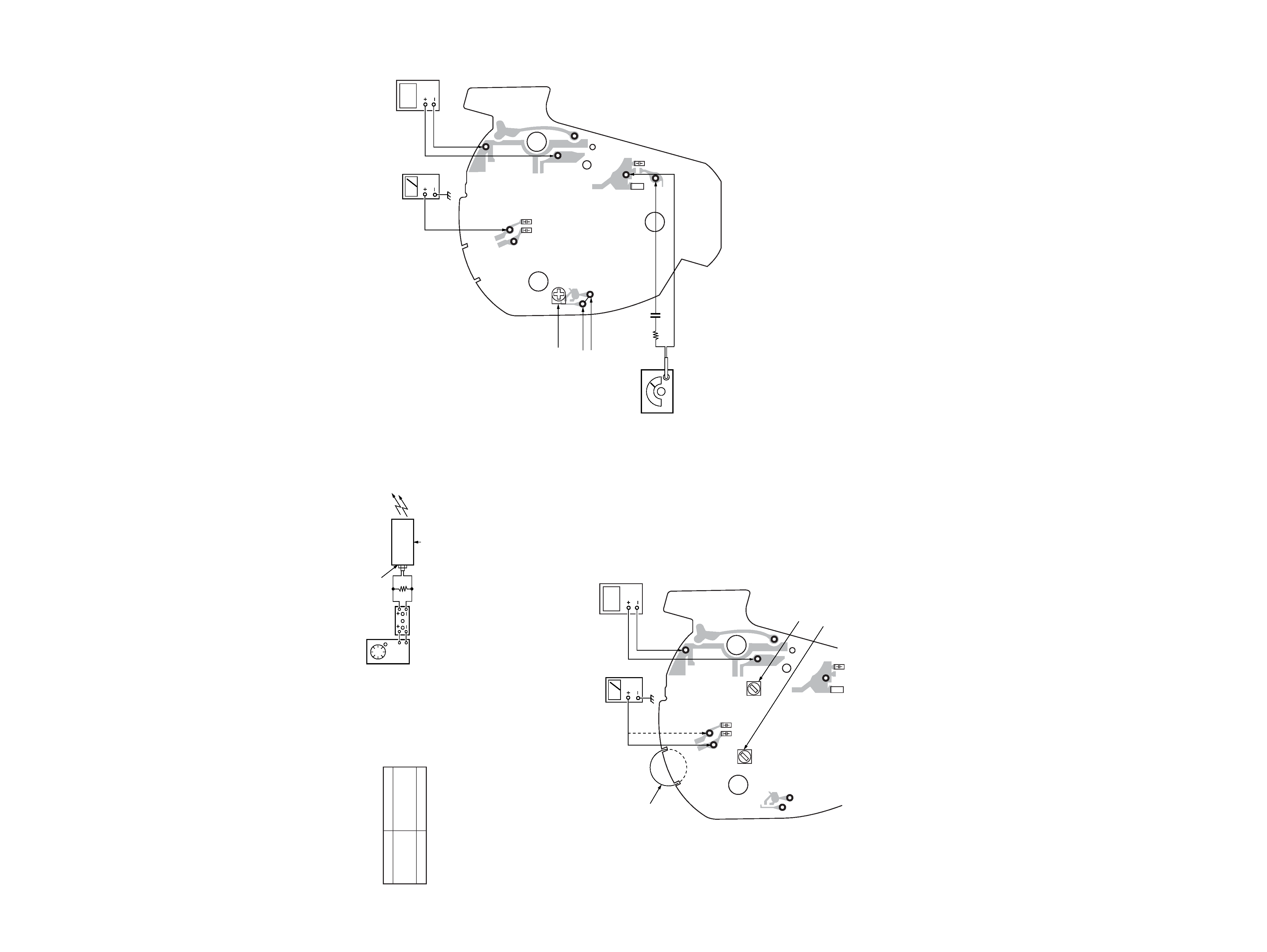
TUNING Adjustment
Preparation :
1. Feedasignaltojig(transmitter)andconnectapowersupplyto
DC IN 9V jack (J4).
2. Appl y DC 1.2V between
TP (VCC) and TP (GND) on the RX
board.
3. SettheR V1(VOL)ontheRXboar
dtotheminim
umposition.
SECTION 2
ELECTRICAL ADJUSTMENT
Note :
1. Thetransmittersectionadjustmentsshouldbecompletedbefore
performingtheheadphonessectionadjustment.
2. Onadjustingtheheadphonessection,usethetransmitterasa
jig.
Headphones
Transmitter
TMR-IF130
MDR-IF230
or
TMR-IF230R
MDR-IF330R
TMR-IF330R
3. TheheadphonessectionadjustmentmustbemadewithPDboard
connectedtotheRXboardwiththespecifiedwire.
4. TheMUTEONPOINTadjustmentmustbemadewhiletaking
care of the photodiodes (D1, D2, D101, D102) not to be ex-
poseddirectlytoexternallights(suchasincandescentlampand
sunlight).
Transmitter
J4
power supply
(DC 9V)
AUDIO IN B jack (J1)
1kHz 245mV (10dB)
AF OSC
ATT
Jig
600
C35
C55
C
3
L
1
TP51
TP31
L53
L32
TP3
TP2
TP
(VCC)
TP
(GND)
TP
(SW)
regulated DC
power suppluy
distortion
meter
TP51
(R-CH)
TP31
(L-CH)
RV1 (VOL)
TP (VCC)
TP (GND)
L32 : Tuning Adjustment (L-CH)
L53 : Tuning Adjustment (R-CH)
[RX BOARD] (Conductor side)
(output :1.2V DC)
Procedure :
1. Connectthedistor
tionmeterto
TP31(L-c h)and TP51(R-c h).
2. Turnonthepo
wer .
3. AdjustwithL32(L-ch)andL53(R-ch)tominimizethereading
onthedistor
tionmeter .
Connection and Adjustment Location :
MUTE ON POINT Adjustment
Connection and Adjustments Location :
Procedure :
1. Shor tthecir cuitbetween
TP2and TP3.
2. Notedownthelevelmeterreadatthistime.
3. Releasetheshor
t-cir cuitbetween
TP2and TP3.
4. AdjustR V2sothatthele
velmeterreadis5dBto10dBbelo
w
thevaluenoteddownatstep2.
C35
C55
C
3
L
1
TP51
TP31
TP3
TP2
TP
(VCC)
TP
(SIG)
TP
(GND)
TP
(SW)
RV2
regulated DC
power suppluy
level meter
TP51
(R-CH)
TP51
(R-CH)
TP3
RV2 : Mute ON point
Adjustment
TP2
TP (SIG)
10k
0.1µF
TP (VCC)
TP (GND)
[RX BOARD] (Conductor side)
FM RF signal
generator
Carrier frequency : 2.8MHz
Modulation :
1kHz
Deviation :
16kHz
Output level :
34dB
µV
(output :1.2V DC)
7
8
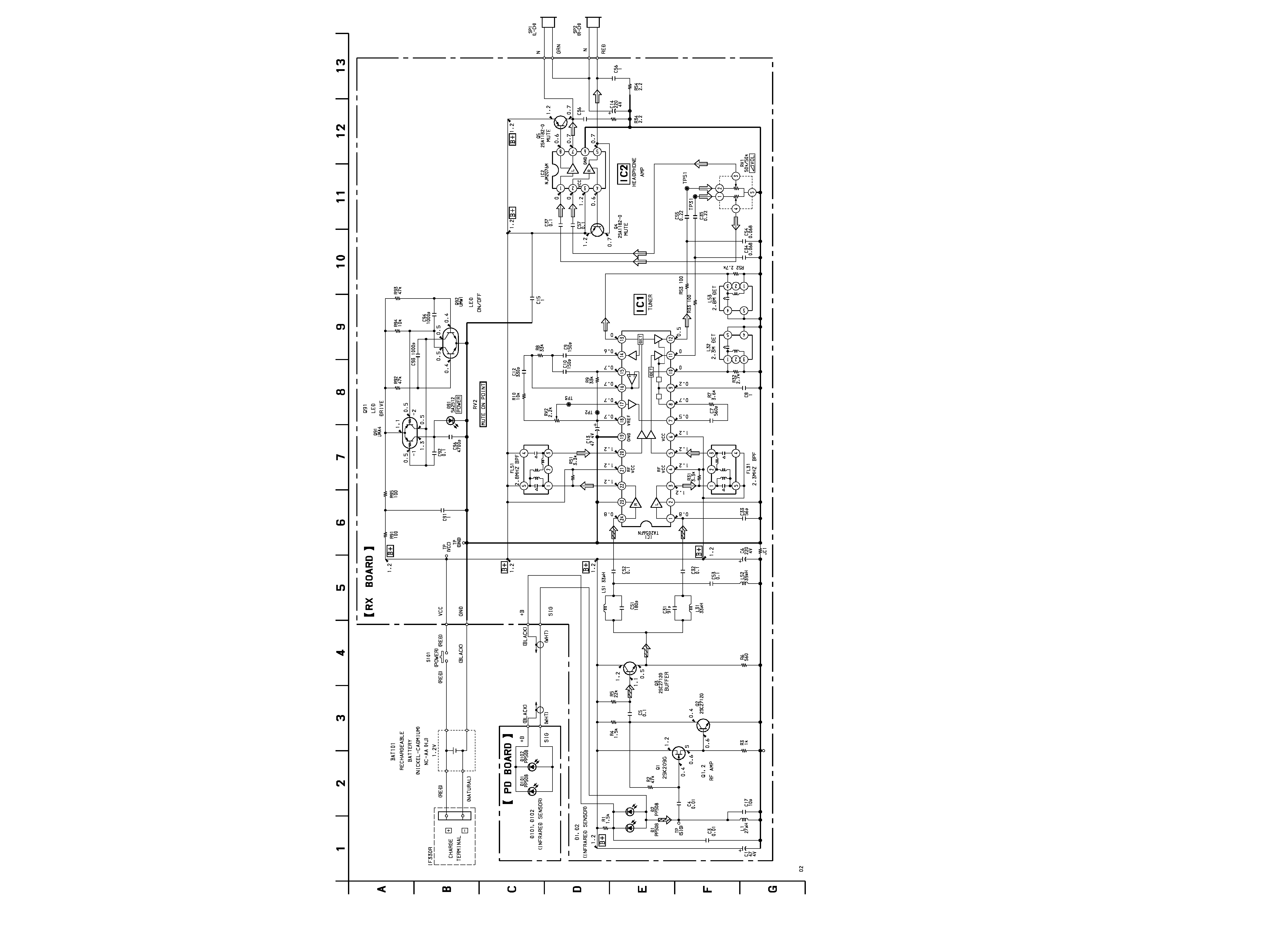
MDR-IF230/IF330R
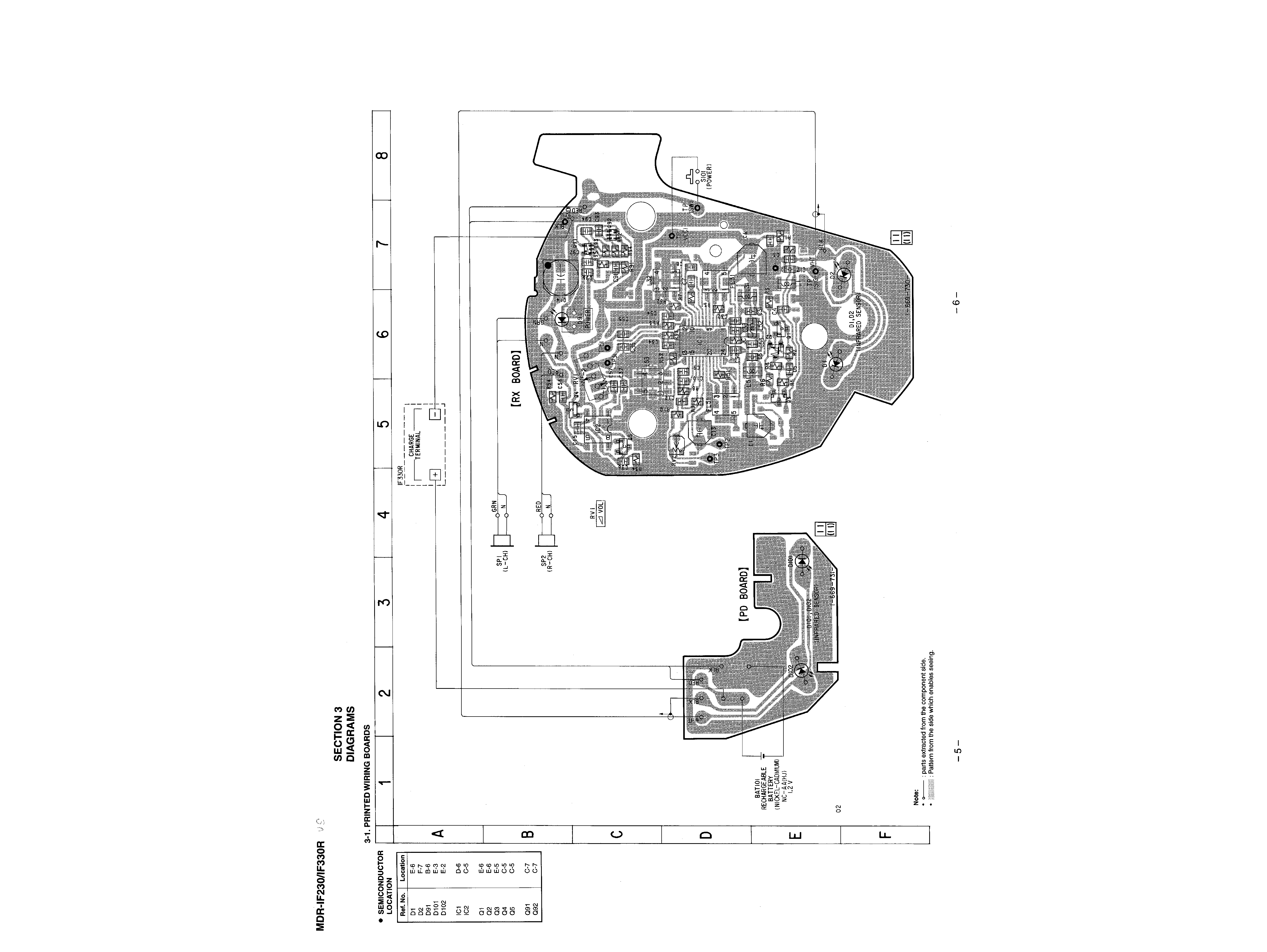
Note:
· All capacitors are in
µF unless otherwise noted. pF: µµF
50 WV or less are not indicated except for electrolytics
and tantalums.
· All resistors are in
and 1/4 W or less unless otherwise
specified.
·
¢
: internal component.
· U : B+ Line.
· H : adjustment for repair.
· Power voltage is dc 1.2V and fed with regulated dc power
supply from battery terminal.
Voltages are dc with respect to ground under no-signal
conditions.
· Signal path.
F
: AUDIO
J
: RF
3-2. SCHEMATIC DIAGRAM