MDR-7505
US Model
AEP Model
SERVICE MANUAL
STEREO HEADPHONES
SPECIFICATIONS
Features
· Monitoring headphones for DJ and remix use
· Swivel earcup allows easy single sided monitoring on shoulders
· 40 mm driver unit for high quality sound
· Coiled OFC litz cord
· Screw type gold plated stereo unimatch plug for secure
connection
· Convenient folding design
Type
: Dynamic, Closed
Driver unites
: ø40 mm, dome type
Impedence
: 40
at 1 kHz
Sensitivety
: 102 dB/mW
Power handling capacity
: 1000 mW
Frequency response
: 10 25,000 Hz
Cord
: Coiled 1 3 m long single-sided OFC-litz cord
with a gold plated stereo unimatch plug
Mass
: Approx. 225 g (wihtout cord)
Supplied accessory
: Soft case (1)
Design and specifications are subject to change without notice.
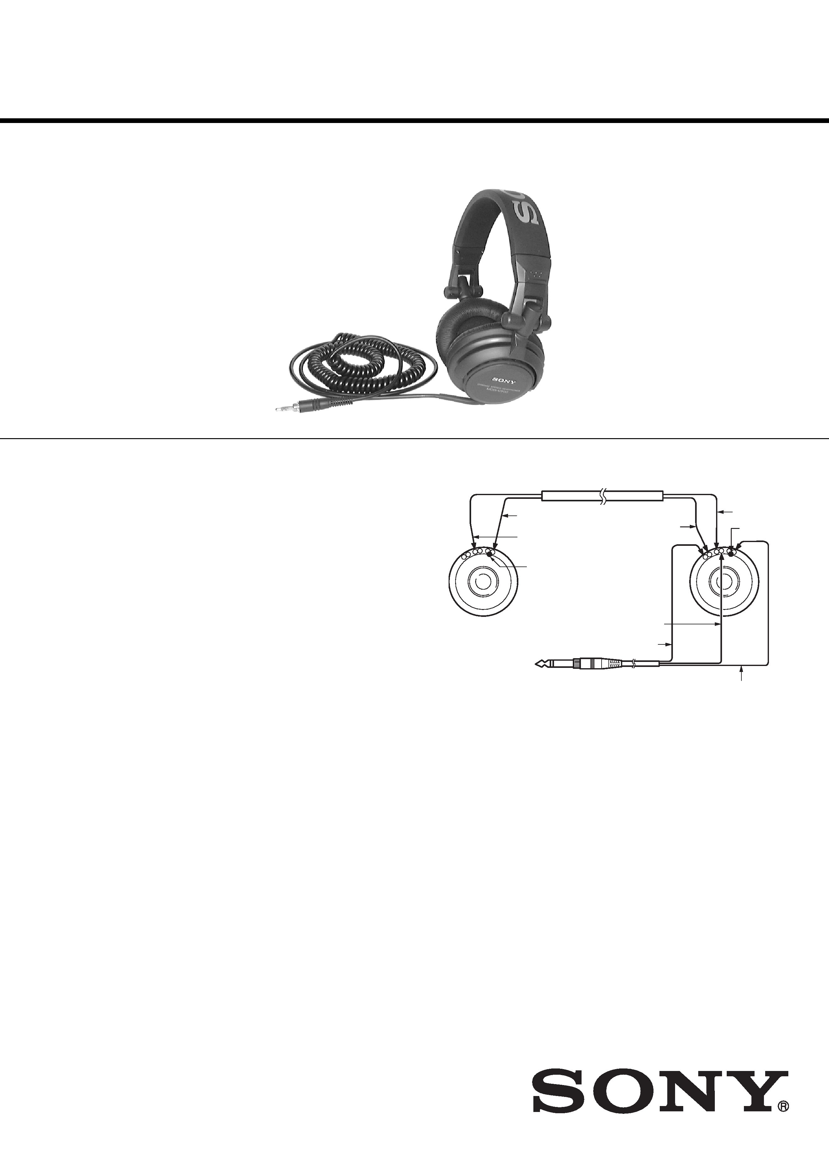
[WIRING DIAGRAM]
(RED)
(RED)
(BRONZE)
(BRONZE)
Marking
Marking
DRIVER
(R)
DRIVER
(L)
(BRONZE)
(GREEN)
(RED)
Ver 1.1 2004.02
Sony Corporation
Personal Audio Company
Published by Sony Engineering Corporation
9-927-155-12
2004B16-1
© 2004.02
-- 2 --
MDR-7505
SECTION 1
DISASSEMBLY
Note :
Disassemble the unit in the order as shown below.
Note :
Follow the disassembly procedure in the numerical order given.
Set
Driver (L side)
Driver (R side)
Cord (with plug)
Hunger (R)
Hunger (L)
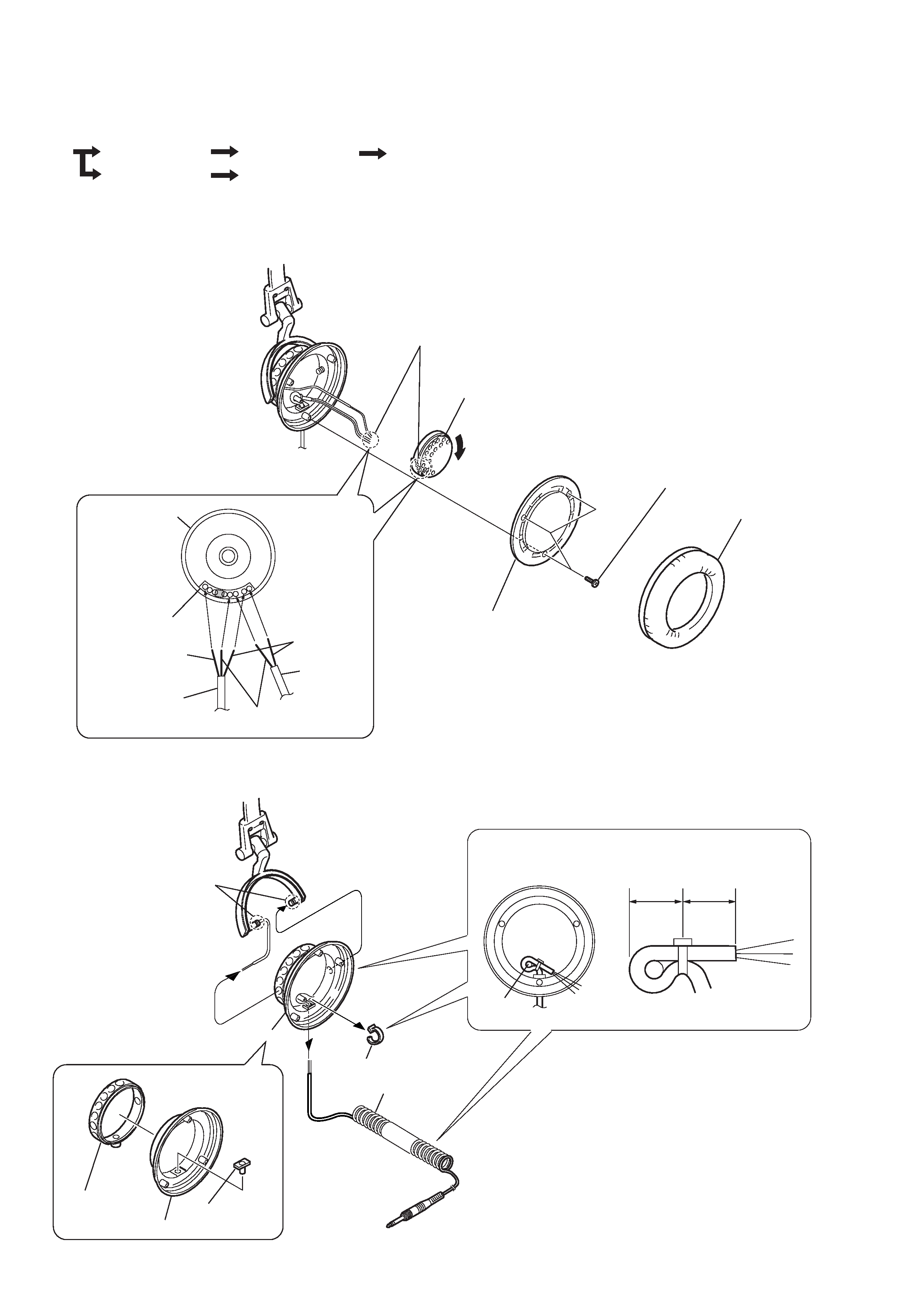
1-1. DRIVER (L SIDE)
1-2. CORD (WITH PLUG)
1 Ear pad
2 Three screws (+P2.6
× 6)
3 Front assembly plate
4 Rotate it in the direction of the arrow.
6 Driver (headphone) (040F016)
5 Remove the
five solderings
Red
Cord
(with plug)
Marking side
Driver (L side)
Green
Precaution during installation
Harness
Natural
1 Remove the wiring bracket.
3 Two claws
2 Cord
(with plug)
A
15 mm
15 mm
1 Bushing
3 Housing (L)
2 Housing
ring (L)
4
Precaution during installation
Hook the loop of the
cordaround the rib of
the portion A.
Fasten the cord at the specified
dimension as shown, to cut the
excessive length.
-- 3 --
MDR-7505
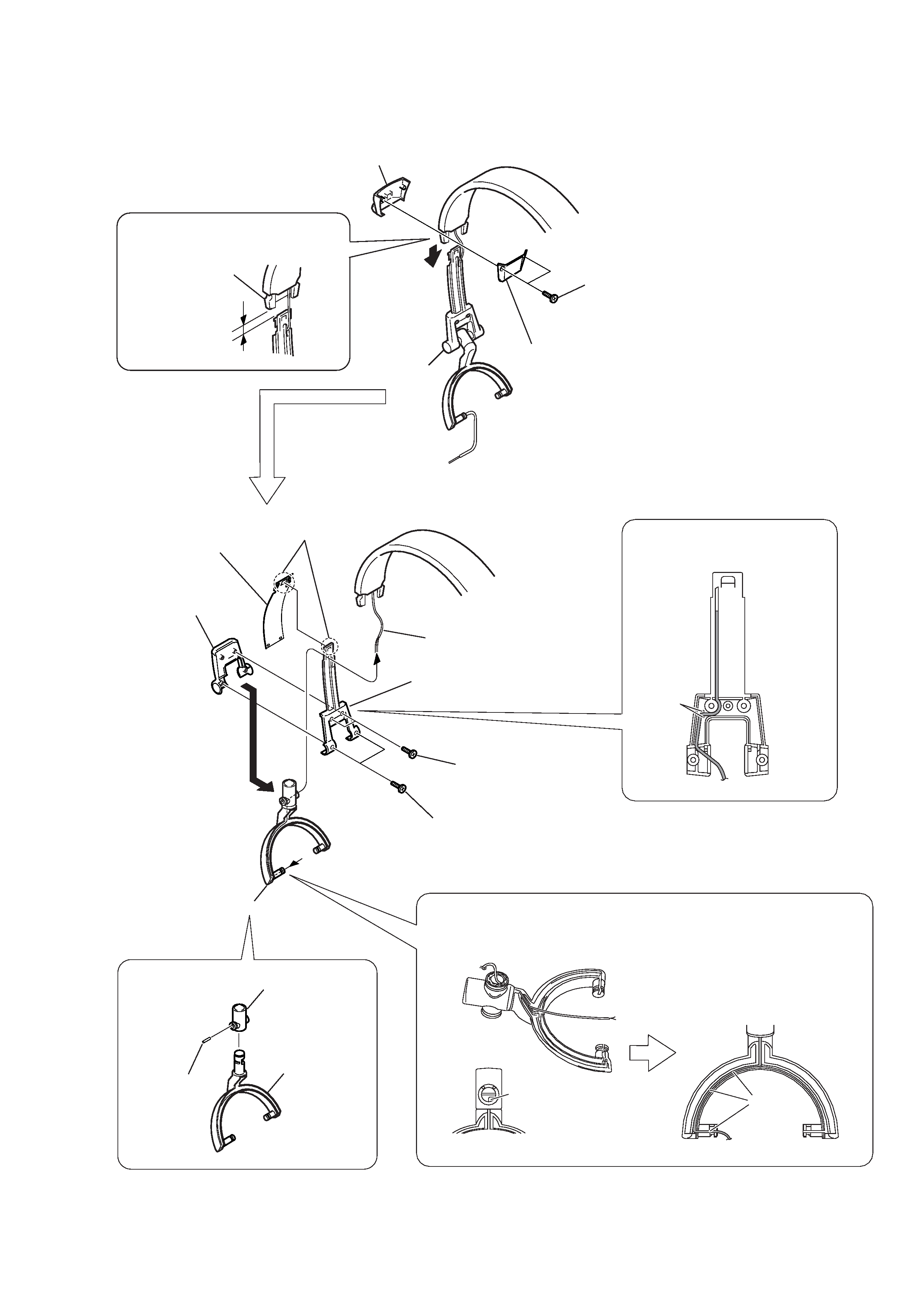
1-3. HUNGER (L)
A
9 Slider cap lid (L)
C
1 Two screws (+P2
× 6)
1 Two screws
(+P2
× 6)
2 Two screws
(+P2
× 6)
3 Slider cap (L)
4
2 Cushion stopper
(upper)
3 Cushion stopper (lower) (L)
5
2 Ginbal (L)
1 Ginbal shaft
8
3 Hunger (L)
7 Harness
4 Claw
5 Slider
6
Slider holder (L side)
0 2 mm
B
Precaution during installation
Precaution during installation
Precaution during installation
Adjust the distance between
the slider holder and harness
to the specified distance as shown.
Route the harness into
the groove and the rib of
the portion A as shown.
Place the hunger in the direction as shown
and route the harness coming from the slider
cap lid through the hole of the portion B on the Ginbal.
Route the harness into
the groove inside the portion C.
-- 4 --
MDR-7505
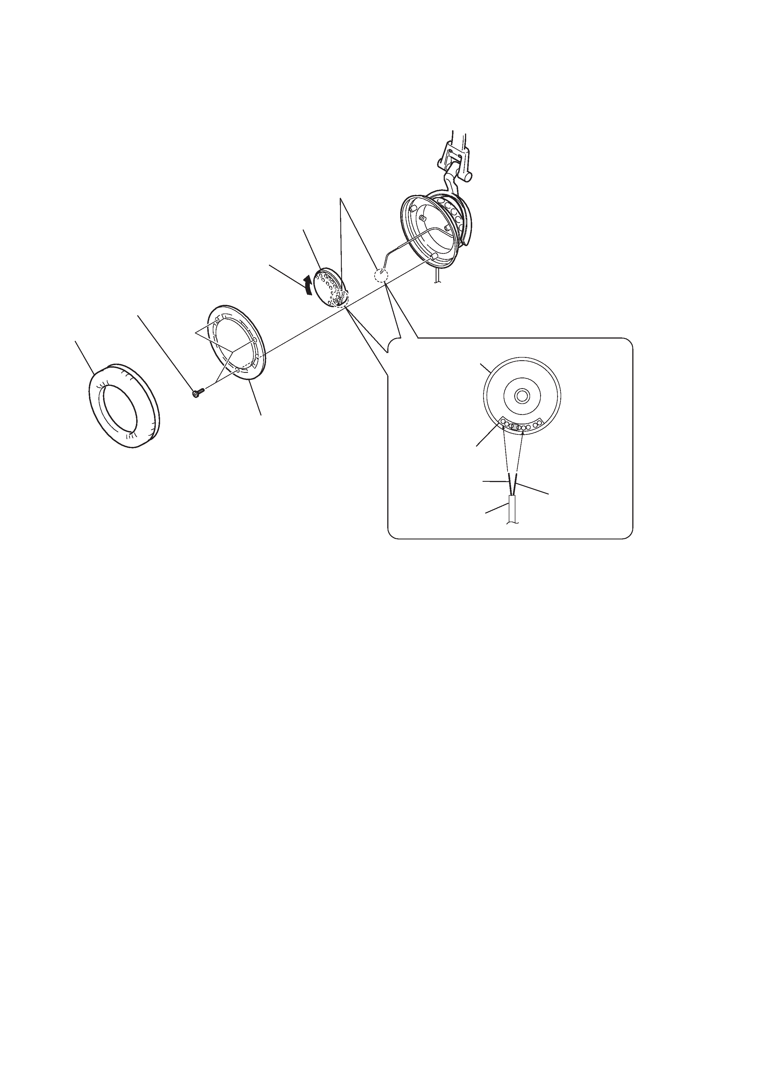
1-4. DRIVER (R SIDE)
1 Ear pad
2 Three screws
(+P2.6
× 6)
3 Front assembly plate
6 Driver (headphone)
(040F016)
5 Remove the
two solderings
Marking side
Driver (R side)
Red
Precaution during installation
Harness
Natural
4 Rotate it in the direction
of the arrow.
-- 5 --
MDR-7505
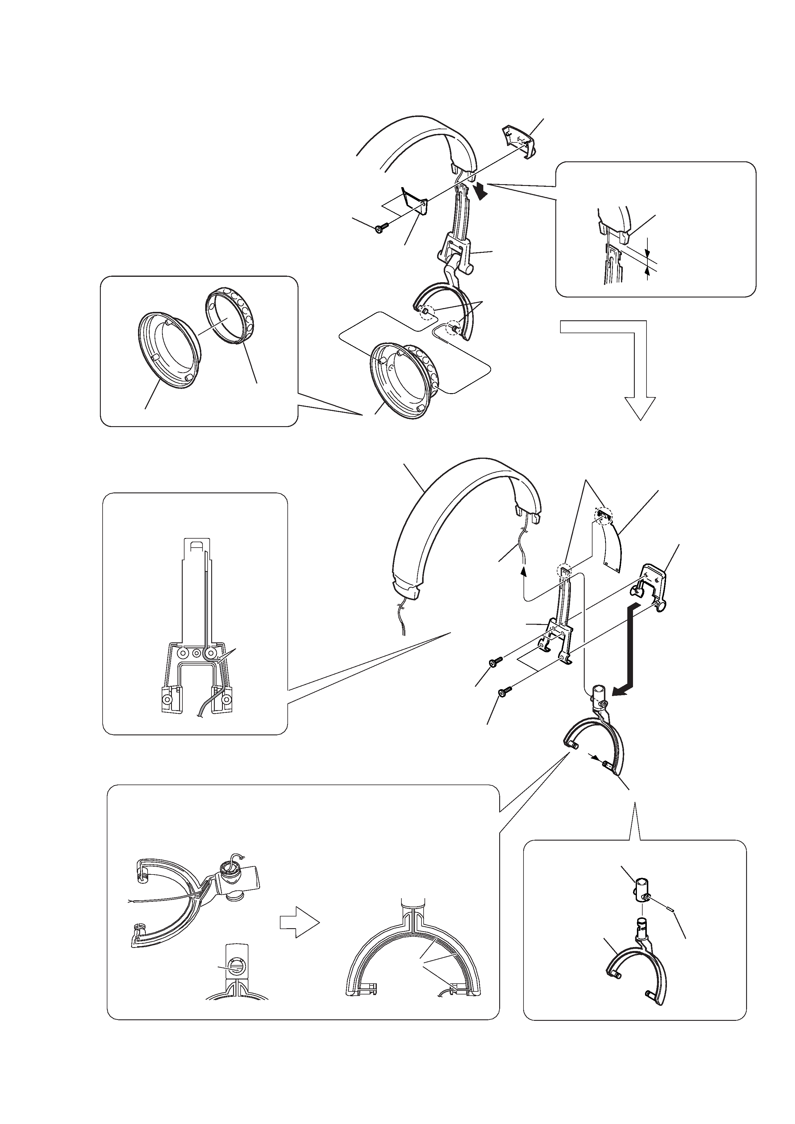
1-5. HUNGER (R)
3 Two screws
(+P2
× 6)
Slider holder (R side)
1 Two claws
Head band unit
1 Two screws
(+P2
× 6)
2 Two screws
(+P2
× 6)
9 Slider cap lid (R)
3 Slider cap (R)
6
4 Cushion stopper
(upper)
0 2 mm
5 Cushion stopper (lower) (R)
7
2
2 Ginbal (R)
1 Ginbal shaft
8
3 Hunger (R)
7 Harness
4 Claw
A
BC
5 Slider
6
2 Housing (R)
1 Housing
ring (R)
Precaution during installation
Precaution during installation
Precaution during installation
Adjust the distance between the slider
holder and harness to the specified
distance as shown.
Route the harness into the groove
and the rib of the portion A as shown.
Place the hunger in the direction as shown
and route the harness coming from the slider
cap lid through the hole of the portion B on the Ginbal.
Route the harness into the
groove inside the portion C.