MCE-CX80K
E Model
SERVICE MANUAL
VIDEO CD PLAYER
SPECIFICATIONS
Model Name Using Similar Mechanism
NEW
CD Mechanism Type
CDM59-5BD24
Base Unit Name
BU-5BD24
Optical Pick-up Name
KSS-213B/S-N
VIDEO CD player
Laser
Semiconductor laser (
=780nm)
Emission duration: continuous
Laser output
MAX 44.6
µ W
* This output is the value measured at
a distance of 200 mm from the
objective lens surface on the Optical
Pick-up Block with 7 mm aperture.
Wavelength
780 - 790 nm
Signal format system
NTSC, PAL
Frequency response
20 Hz to 20 kHz
±1.0 dB
Outputs
Jack
type
Maximum
output
level
Load impedance
AUDIO OUT Phono
jacks
1.43 V
(at 50 kilohms)
Over 10 kilohms
VIDEO
OUT
Phono
jack
1 Vp-p
75 ohms, unbalanced,
sync negative
Inputs
Jack
type
Maximum
input
level
Load impedance
MIC 1,
MIC 2
Phone
jack
100 mVp-p
600 ohms
General
Power requirements
110 - 120 V or 220 - 240 V AC,
adjustable, 50/60 Hz
Power consumption
24 W
Dimensions (approx.)
430
110
398 mm
(w/h/d)
incl. projecting parts
Mass (approx.)
5.3 kg
Supplied accessories
Audio and video connecting cord (1)
Remote commander (remote) RMT-C98V (1)
Sony R6 (size AA) batteries (2)
Design and specifications are subject to change without notice.
2
1. SERVICING NOTES ······················································ 3
2. TEST MODE ······································································ 4
3. GENERAL ·········································································· 6
4. DISASSEMBLY
4-1.
UPPER CASE, BOTTOM PLATE, FRONT PANEL ········ 7
4-2.
BACK PANEL AND DISC TABLE ·································· 7
4-3.
DISP, SWI, VOL AND KARAOKE MIC BOARDS ········· 8
4-4.
CD MECHANISM DECK (CDM59-5BD24) ··················· 8
4-5.
JACK, VIDEO AND MAIN BOARDS ····························· 9
4-6.
BASE UNIT (BU-5BD24) ················································· 9
4-7.
TABLE ASS'Y ································································ 10
4-8.
TRAY, BELT (ROTARY) AND SENSOR BOARD ········ 10
4-9.
BELT (LOADING)
AND LOADING MOTOR BOARD ································ 11
4-10. ADJUSTING PHASE OF
SWING GEAR AND GEAR (U/D) ································ 12
5. ELECTRICAL ADJUSTMENTS
CD Section ··········································································· 13
6. DIAGRAMS
6-1.
Block Diagrams
· Servo Section ································································ 14
· Audio/Video Section ····················································· 15
· Disp/Key Control/ Power Supply Section····················· 16
6-2.
Circuit Boards Location ··················································· 17
6-3.
Printed Wiring Board Video Section ·························· 21
6-4.
Schematic Diagram Video Section (1/2) ··················· 22
6-5.
Schematic Diagram Video Section (2/2) ··················· 23
6-6.
Schematic Diagram BD Section ································ 24
6-7.
Printed Wiring Board BD Section ····························· 25
6-8.
Schematic Diagram Main Section ····························· 26
6-9.
Printed Wiring Board Main Section ··························· 27
6-10. Schematic Diagram Disp Section ······························ 28
6-11. Printed Wiring Board Disp Section ··························· 29
6-12. Printed Wiring Board
JUNCTION/LOADING/MOTOR Section ················ 30
6-13. Schematic Diagram
JUNCTION/LOADING/MOTOR Section ················ 31
6-14. IC Block Diagrams ·························································· 32
6-15. IC Pin Function Descriptions ··········································· 34
7. EXPLODED VIEWS
7-1.
CASE SECTION ····························································· 40
7-2.
FRONT PANEL SECTION ············································· 41
7-3.
CHASSIS SECTION ······················································· 42
7-4.
CD MECHANISM DECK SECTION-1
(CDM59-5BD24) ····························································· 43
7-5.
CD MECHANISM DECK SECTION-2
(CDM59-5BD24) ····························································· 44
7-6.
BASE UNIT SECTION (BU-5BD24) ····························· 45
8. ELECTRICAL PARTS LIST ····································· 46
Notes on chip component replacement
· Never reuse a disconnected chip component.
· Notice that the minus side of a tantalum capacitor may be dam-
aged by heat.
This appliance is classified as a CLASS 1 LASER product. The
CLASS 1 LASER PRODUCT MARKING is located on the rear
exterior.
The following caution label is located inside the unit.
Laser component in this product is capable
of emitting radiation exceeding the limit for
Class 1.
CAUTION
Use of controls or adjustments or performance of procedures
other than those specified herein may result in hazardous radiation
exposure.
The components identified by mark 0 or dotted
line with mark 0 are critical for safety.
Replace only with part number specified.
SAFETY-RELATED COMPONENT WARNING!!
COMPONENTS IDENTIFIED BY MARK 0 OR DOTTED LINE WITH
MARK 0 ON THE SCHEMATIC DIAGRAMS AND IN THE PARTS
LIST ARE CRITICAL TO SAFE OPERATION. REPLACE THESE
COMPONENTS WITH SONY PARTS WHOSE PART NUMBERS
APPEAR AS SHOWN IN THIS MANUAL OR IN SUPPLEMENTS
PUBLISHED BY SONY.
TABLE OF CONTENTS
3
SECTION 1
SERVICING NOTES
The laser diode in the optical pick-up block may suffer electrostatic
break-down because of the potential difference generated by the
charged electrostatic load, etc. on clothing and the human body.
During repair, pay attention to electrostatic break-down and also
use the procedure in the printed matter which is included in the
repair parts.
The flexible board is easily damaged and should be handled with
care.
NOTES ON LASER DIODE EMISSION CHECK
The laser beam on this model is concentrated so as to be focused on
the disc reflective surface by the objective lens in the optical pick-
up block. Therefore, when checking the laser diode emission,
observe from more than 30 cm away from the objective lens.
LASER DIODE AND FOCUS SEARCH OPERATION
CHECK
Carry out the "S curve check" in "CD section adjustment" and check
that the S curve waveform is output repeatedly.
NOTES ON HANDLING THE OPTICAL PICK-UP
BLOCK OR BASE UNIT
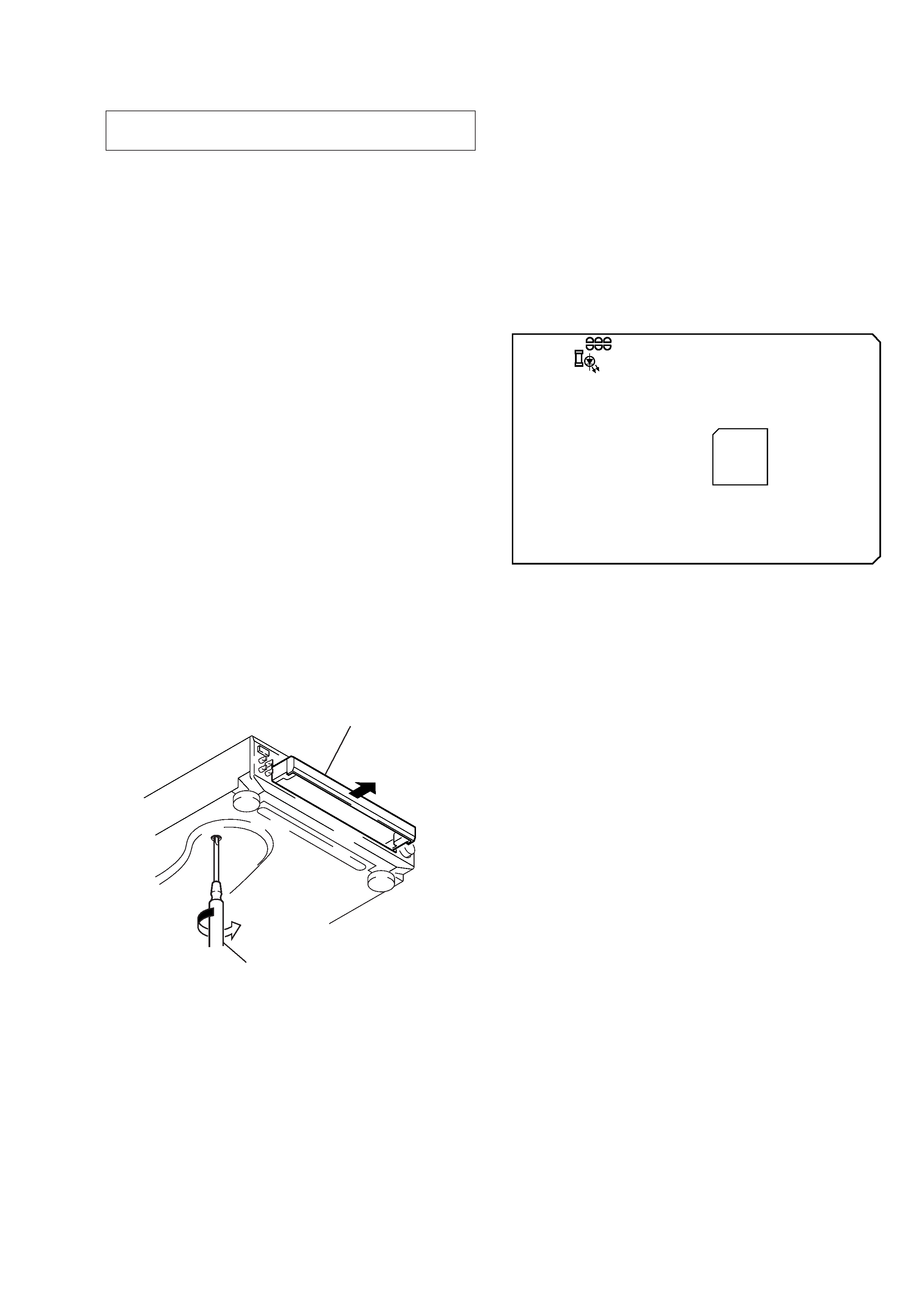
HOW TO OPEN THE DISC TRAY WHEN POWER SWITCH
TURNS OFF
Insert a tapeing driver into the aperture of the unit bottom, and turn
in the direction of arrow (to OUT direction).
* To close the disc table, turn the driver in the reverse direction
(to IN direction).
SELF-DIAGNOSIS
This unit is equipped with a self-diagnosis function.
The function is used for diagnosing the conditions of the circuits of
the VIDEO board.
The circuits can be determined if normal or abnormal by the lighting
of D502 on the VIDEO board.
Lighting of D502
When lit
: Operates normally
Blinks repeatedly : The circuit may be faulty.
[VIDEO Board] (Side B)
table
tapering driver
D502
IC505
The following extension cable is required to check and adjust the
VIDEO board.
J-2501-155-A
CN601/MAIN
CN451/VIDEO
J-2501-156-A
CN906/MAIN
CN453/VIDEO
J-2501-157-A
CN101/BD
CN501/VIDEO
* To close the disc table, turn the tapering
driver in the reverse direction (to IN direction).
4
SECTION 2
TEST MODE
[VIDEO CD Color-bars Mode]
On this mode, the data of the color-bars signal as a picture signal and the 1 kHz sine wave signal as a sound signal are output by the
mechanism controller (IC502) for the video CD signal check. When measurement of the voltage and waveform on the VIDEO board,
perform it in this mode.
For reference, the color-bars signal can be observed at J302/JACK board (VIDEO OUT) and the sound signal can be observed at CNJ151/
MAIN board (AUDIO OUT) using an oscilloscope.
Procedure:
1. Connect the lead wire to both ends of the land of SL503 on the VIDEO board.
2. Turn the power on.
3. After 2 or 3 seconds later, connect the lead wire.
4. After measuring, remove the lead wire connected.
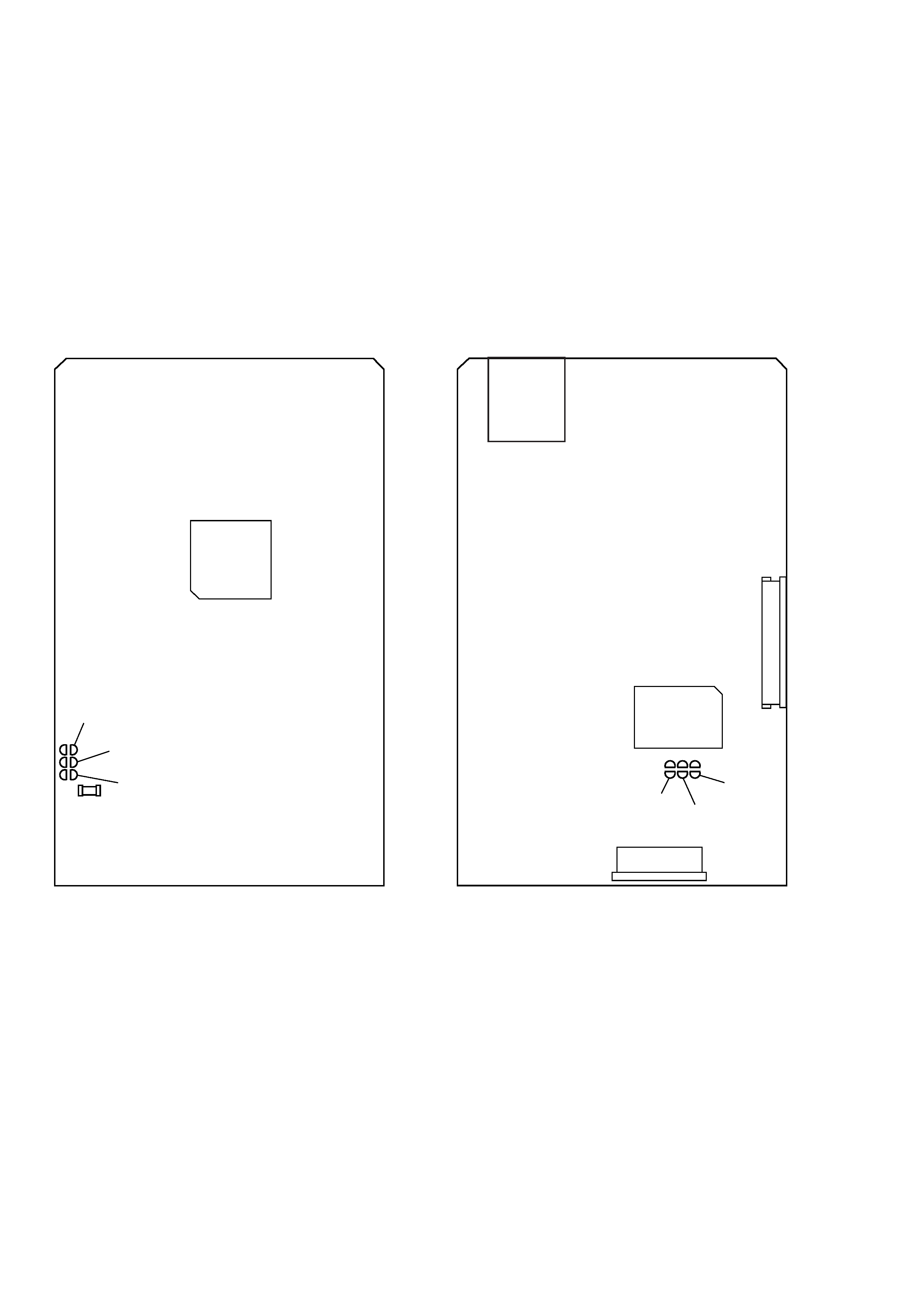
[VIDEO Board] (Side B)
[VIDEO Board] (Side A)
D502
SL501
SL503
SL502
IC505
SL503
IC502
CN302
CN503
CN501
SL502
SL501
5
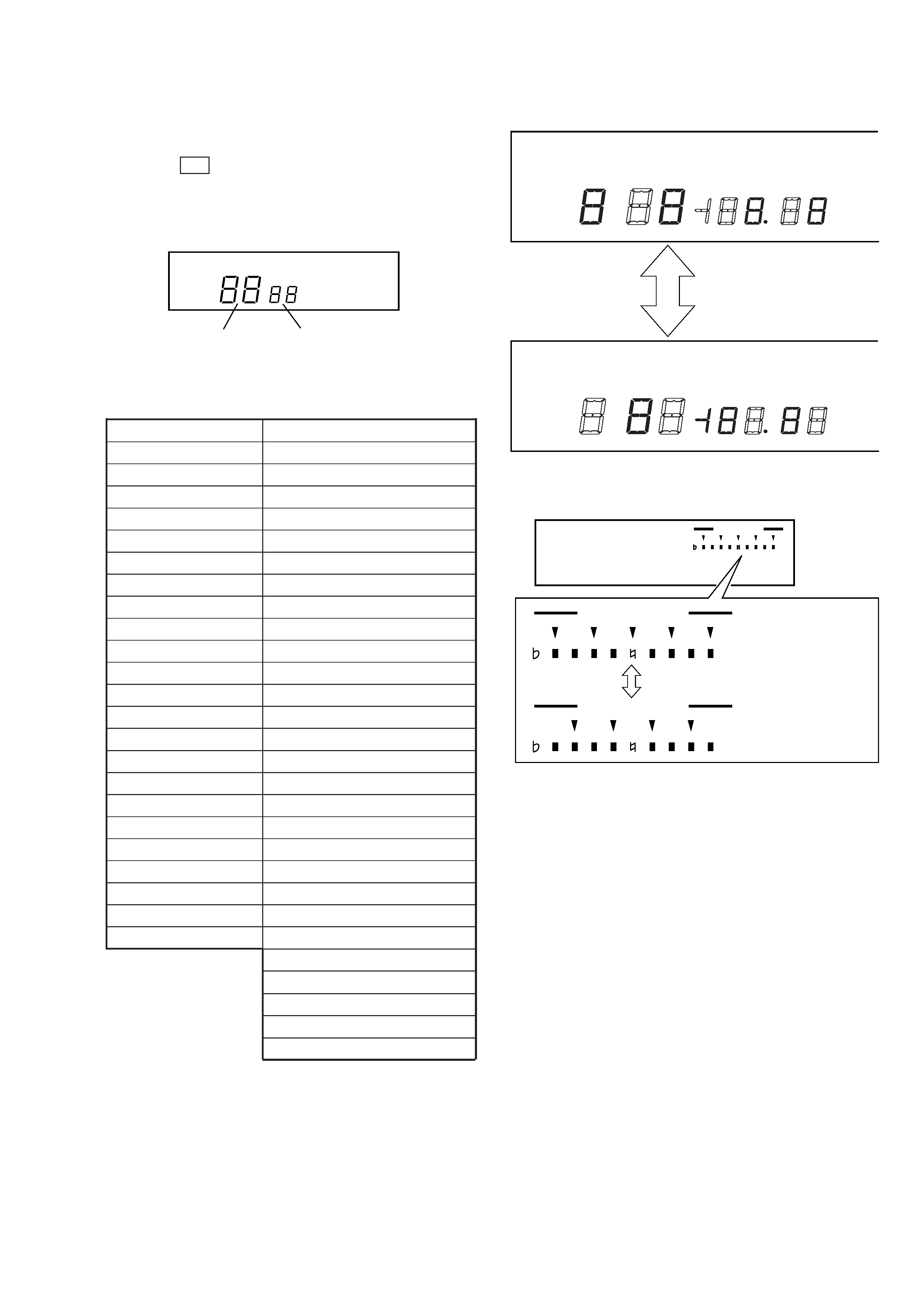
[Fluorescent Indicator Tube and Key Check Mode]
1. Short-circuit the SL501 on the VIDEO board.
2. Press the
1/u button to turn ON the power.
The whole fluorescent indicator tube light up.
3. All buttons have individual button numbers.
When a button is pressed, the button number is counted up and
displayed.
4. To exit the mode, disconnect the power code from the outlet.
Button
Button Number or Display
1/u
15
KARAOKE PON
77
§ OPEN/CLOSE
16
PICTURE
49
SOUND
5d
· (PLAY) SELECT
Partial lighting 1
P (PAUSE)
Partial lighting 2
p (STOP)
All lit
PREV
30
NEXT
31
RETERN
0E
~
6C
NATURAL
67
n
6b
DISC1
40
DISC2
41
DISC3
42
DISC4
43
DISC5
44
JOG SELECTOR (button) 81
JOG SELECTOR (knob)
When roatated colck wise:
DISC SKIP
The key control indicators
EX-CHANGE
light up from left to right.
When rotated counter colck wise:
The key control indicators
light up from right to left.
3E
3F
Buttons and Corresponding Button Numbers
Partial lighting 2
Partial lighting 1
Count up display
Display button number
Light alternately
KEY CONTROL
#
KEY CONTROL
Light alternately
#
KEY CONTROL
#