MICROFILM
M-100MC
SERVICE MANUAL
MICROCASSETTETM-CORDER
SPECIFICATIONS
US Model
Canadian Model
AEP Model
E Model
Tourist Model
Tape
y (normal position type)
Recording system
2-track 1-channel monaural
Speaker
Approx. 2.8cm (1 1/8 in.) dia.
Tape speed
2.4cm/s (15/16 ips), 1.2cm/s (15/32 ips)
Frequency range
High : 400 3,000Hz
Normal, Low : 400 4,000Hz
Output
Earphone jack (minijack) for 8 300ohms earphone
Power output (at 10% harmonic distortion)
220mW
Battery life (Approx. hours) (EIAJ*)
Batteries
Recording
Sony alkaline LR6 (SG)
16.0
Sony R6P (SR)
5.5
* Measured value by the standard of EIAJ (Electronic Industries
Association of Japan) (Using a Sony Microcassette MC-60)
Power requirements
3V DC
Two R6 (size AA) batteries
Dimensions (w/h/d)
Approx. 126.0 x 68.0 x 40.8 mm (5 x 2 3/4 x 15/8 in.) incl.
projecting parts and controls
Mass
Approx. 180g (6.4 oz) incl. batteries
Supplied Accessories
Hand strap (attached to the unit) (1)
Microcassette tape (1) (EXCEPT US, Canadian, AEP model)
Wind screen (1) (US model)
R6 (size AA) batteries (2) (Tourist model)
Earphone (1) (Tourist model)
Design and specifications are subject to change without notice.
Model Name Using Similar Mechanism
NEW
Tape Transport Mechanism Type
MZ-100MC-14
2
Specifications ........................................................................... 1
1. GENERAL
Location and Function of Controls .................................... 2
2. DISASSEMBLY
2-1. Rear Cabinet Assy Removal ....................................... 3
2-2. Front Cabinet Assy, Main Unit Removal .................... 3
2-3. Mechanism Deck Removal ......................................... 4
2-4. MIC-SP Block Assy, Main Board Removal ............... 4
2-5. LED Board, Cassette Lid Assy Removal ................... 5
2-6. Eject Arm Installation ................................................. 5
3. ADJUSTMENTS
3-1. Mechanical Adjustments ............................................ 6
3-2. Electrical Adjustments ................................................ 6
4. DIAGRAMS
4-1. Block Diagram ............................................................ 8
4-2. Printed Wiring Boards .............................................. 10
4-3. Schematic Diagram ................................................... 13
5. EXPLODED VIEWS
5-1. Front Section ............................................................ 17
5-2. Mechanism Deck Section ......................................... 18
6. ELECTRICAL PARTS LIST .................................... 19
Flexible Circuit Board Repairing
·
Keep the temperature of the soldering iron around 270°C
during repairing.
·
Do not touch the soldering iron on the same conductor of the
circuit board (within 3 times).
·
Be careful not to apply force on the conductor when
soldering or unsoldering.
Notes on chip component replacement
·
Never reuse a disconnected chip component.
·
Notice that the minus side of a tantalum capacitor may be
damaged by heat.
TABLE OF CONTENTS
SECTION 1
GENERAL
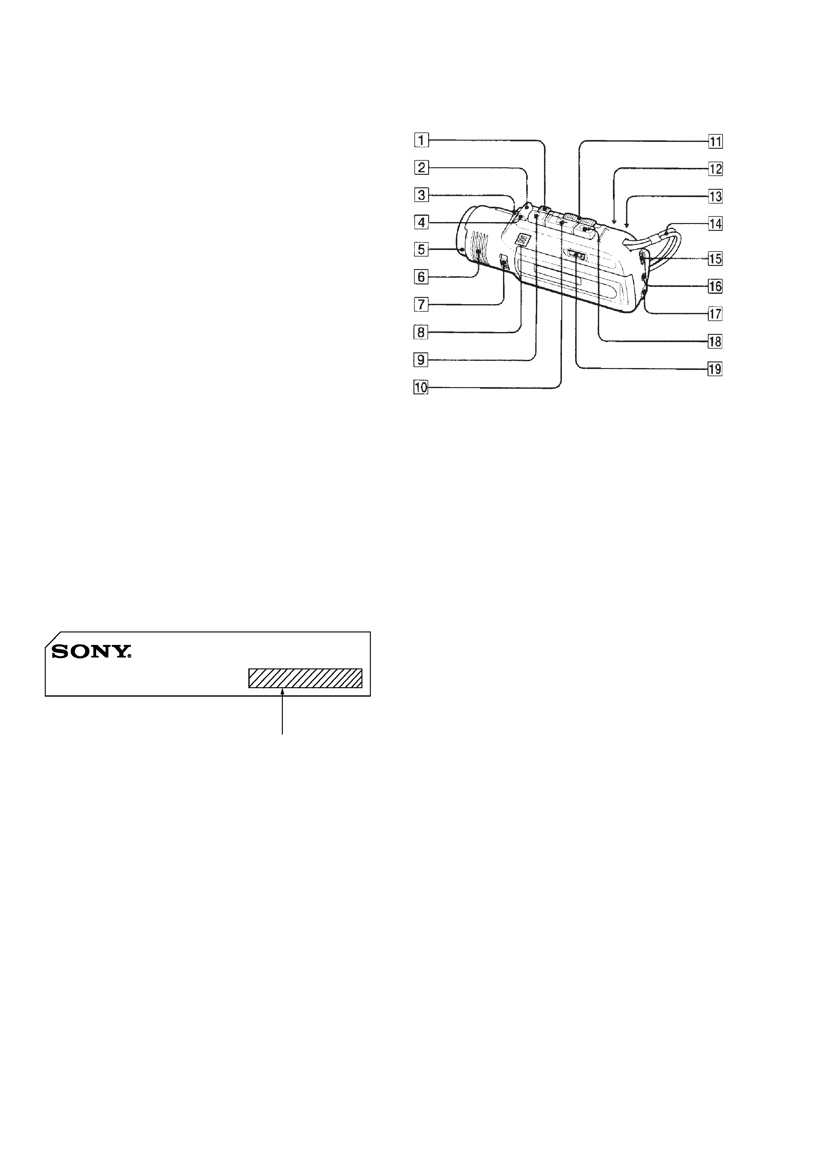
LOCATION AND FUNCTION OF CONTROLS
MICROCASSETTE-CORDER M-100MC
MODEL IDENTIFICATION
Indication of country of origin :
US, Canadian, AEP, E, Tourist model
No indication of country of origin : 1E model
1 P PAUSE switch
2 CUE MARKER button
3 VOL control
4 REC indicator
5 Microphone
6 Speaker
7 SENSITIVITY selector
8 BATT indicators and i indicator
9 r (recording) button
!º ( (playback) button
!¡ ) (fast-forward)/(cue) · 0 (rewind)/(review) switch
!TM VOR switch
!£ FIRST PB switch
!¢ Handstrap
! TAPE SPEED switch
!§ EAR jack
!¶ DC IN 3V jack
!· p, (stop/eject) button
!ª TAPE COUNTER
3
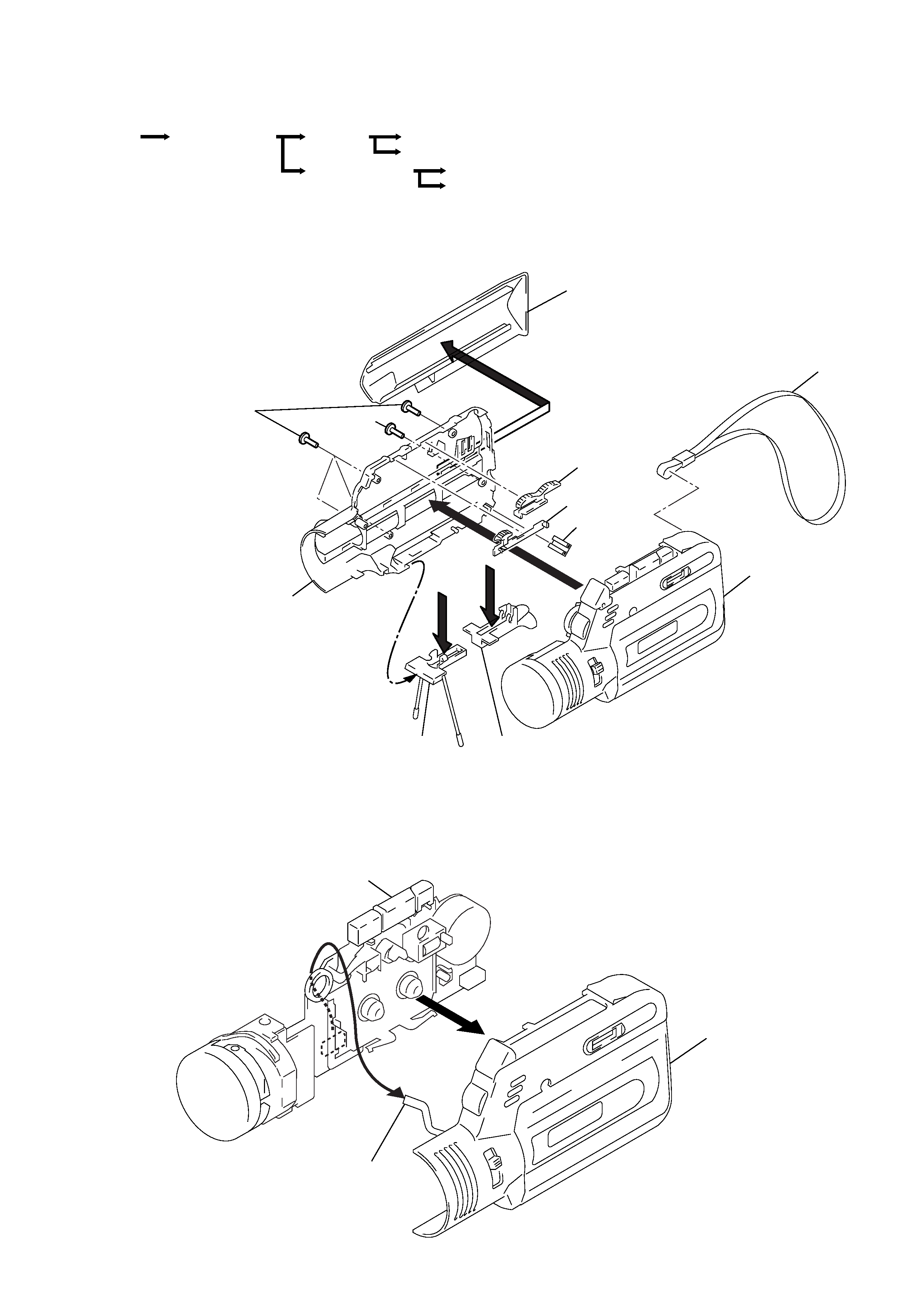
SECTION 2
DISASSEMBLY
Note : Follow the disassembly procedure in the numerical order given.
2-1. REAR CABINET ASSY REMOVAL
2-2. FRONT CABINET ASSY, MAIN UNIT REMOVAL
r
The equipment can be removed using the following procedure.
4 Screws (B 1.7x13.5)
5 Screw
(B 1.7x7)
Hand strap
Front cabinet assy
FR knob
Pause knob
Foot (cabinet)
Button (stand)
3
6
2
1
Rear cabinet assy
Stand assy
Lid, battery case
Front cabinet assy
LED flexible board
main board (W101)
Main unit
1
2
Front cabinet assy
Rear cabinet assy
Cassette lid assy
Set
MIC-SP block assy, Main board
Mechanism deck
Main unit
LED board
4
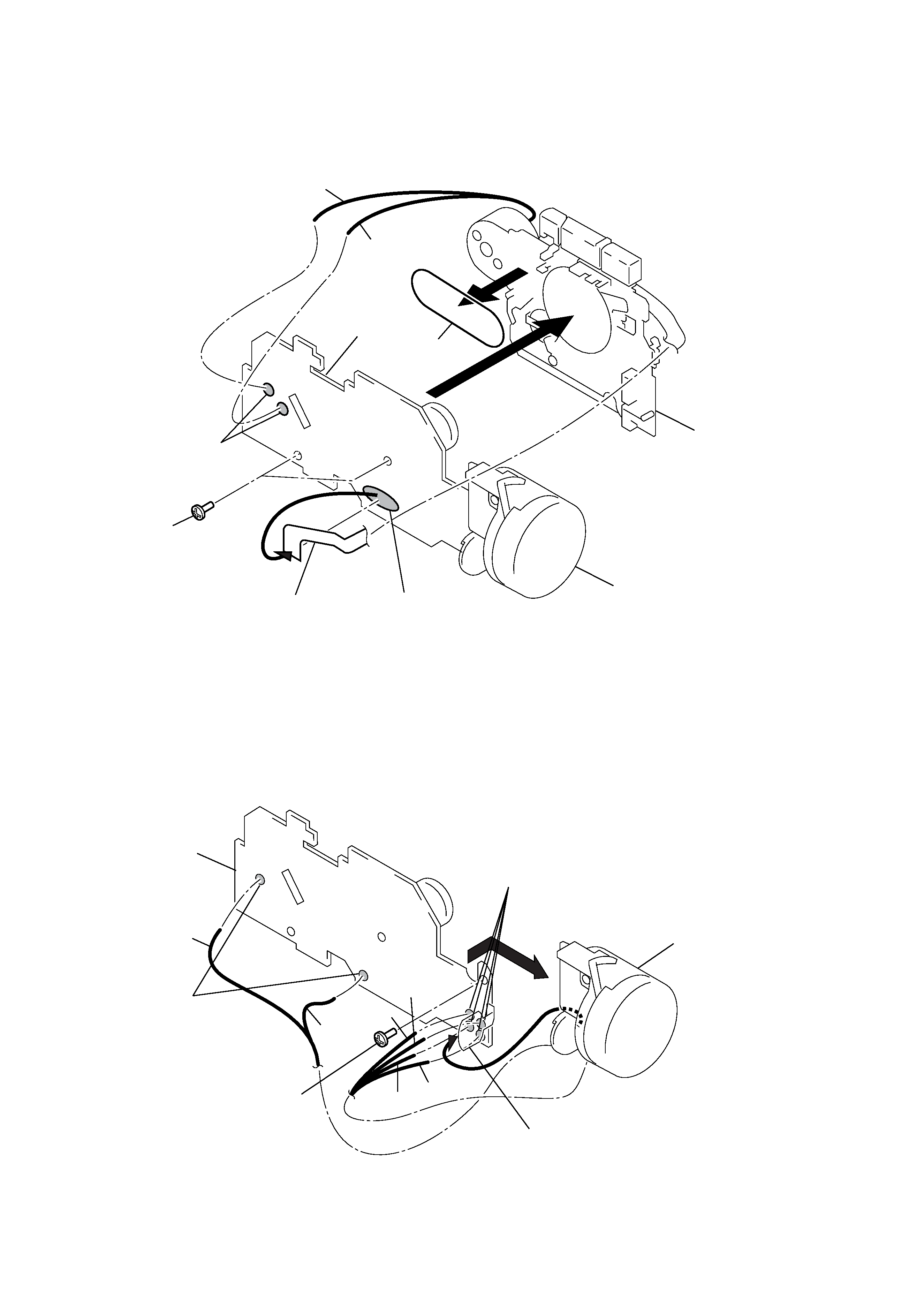
2-4. MIC-SP BLOCK ASSY, MAIN BOARD REMOVAL
2-3. MECHANISM DECK REMOVAL
2 Screw (M1.4)
1 Remove solder
1 Remove solder
MIC-SP block assy
Main board
3
Battery terminal
Yellow
Red
Black
Brown
Yellow
Blue
2 Screws
1 Remove solder
1 Remove solder
3
4
Mechanism deck
MIC-SP block assy
Blue
Red
Head flexble board
Main board
Belt
5
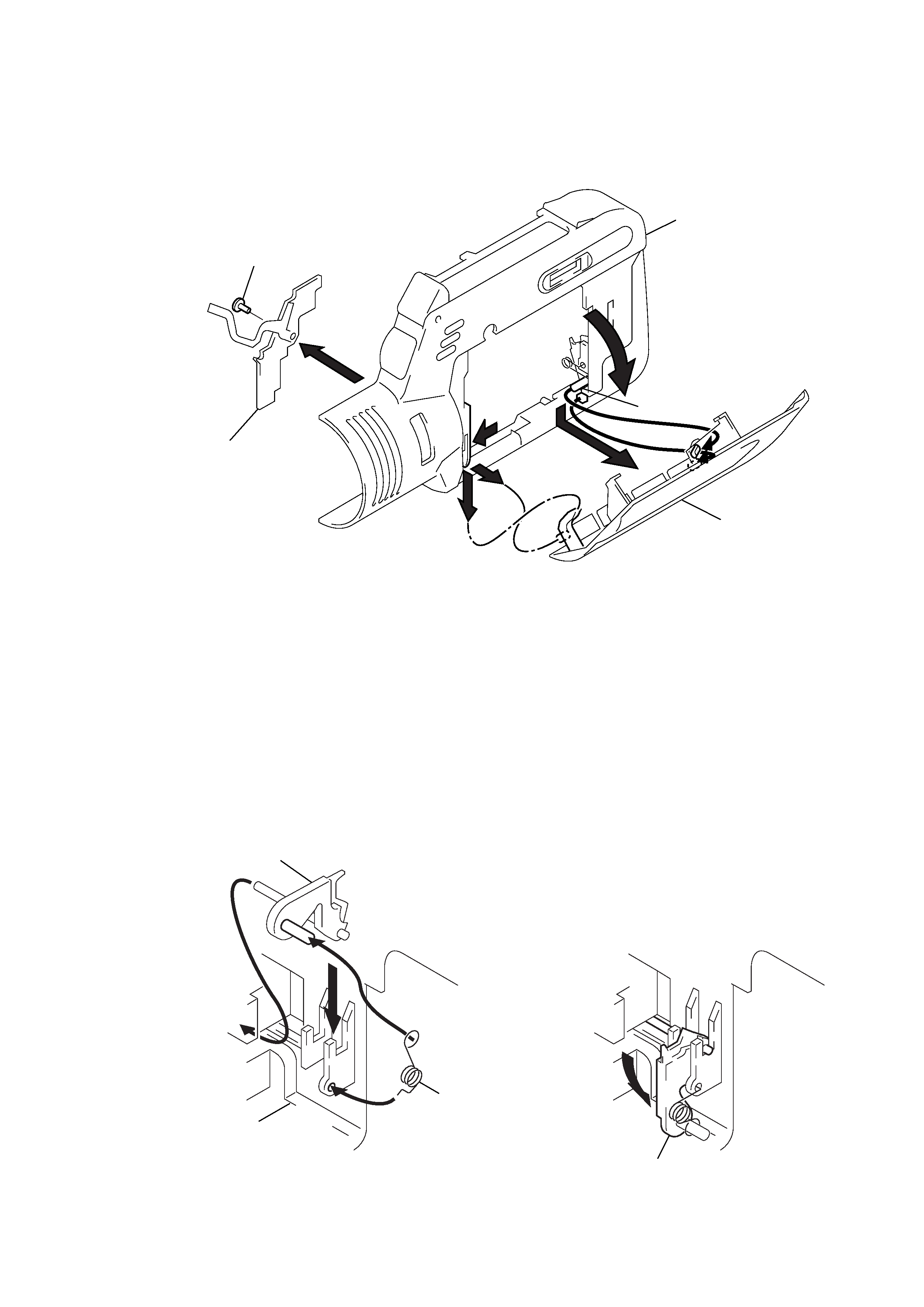
2-5. LED BOARD, CASSETTE LID ASSY REMOVAL
2-6. EJECT ARM INSTALLATION
1 Tapping (1.7x3)
LED board
3
7
5
4
2
6
Cassette lid assy
Front cabinet assy
Eject arm
4
2
3
1
5
Front cabinet assy
Spring (toggle),
torshion
Eject arm
Eject arm