
SERVICE MANUAL
SONY
KVJ29MF1S
MODEL
MC-Service
2
KV-EF29M31/EF29M61/EF29M80/RM-881
EF29M90/EF29M91/EF29M80/RM-881
CAUTION
SHORT CIRCUIT THE ANODE OF HTE PICTURE TUBE
AND THE ANODE CAP TO THE METAL CHASSIS, CRT
SHIELD, OR CARBON PAINTED ON THE CRT, AFTER
REMOVING THE ANODE.
SAFETY-RELATED COMPONENT WARNING!!
COMPONENTS IDENTIFIED BY SHADING AND MARK
¡ ON THE SCHEMATIC DIAGRAMS, EXPLODED
VIEWS AND IN THE PARTS LIST ARE CRITICAL TO
SAFE OPERATION. REPLACE THESE COMPONENTS
WITH SONY PARTS WHOSE PART NUMBERS AP-
PEAR AS SHOWN IN THIS MANUAL OR IN SUPPLE-
MENTS PUBLISHED BY SONY.
MC-Service

3
KV-EF29M31/EF29M61/EF29M80/RM-881
EF29M90/EF29M91/EF29M80/RM-881
1. GENERAL .................................................................
4
2. DISASSEMBLY
2-1.
Rear Cover Removal .........................................
22
2-2.
Speaker Box Assy Removal ..............................
22
2-3.
Chassis Assy Removal ......................................
22
2-4.
Service Position .................................................
22
2-5.
Terminal Bracket, Power Holder,
DH Bracket Removal ........................................
23
2-6.
Picture Tube Removal ........................................
24
2-7.
Wiring Harness Layout ......................................
25
3. SET-UP ADJUSTMENTS ...................................
26
3-1.
Beam Landing ...................................................
26
3-2.
Convergence ......................................................
27
3-3.
Focus Adjustment ..............................................
30
3-4.
G2 (Screen) and White Balance Adjustments ...
31
4. SELF DIAGNOSIS FUNCTION .....................
32
5. CIRCUIT ADJUSTMENTS ................................
33
5-1.
Adjustments with Commander .........................
33
5-2.
Adjustment Method ...........................................
34
5-3.
Picture Quality Adjustments .............................
39
5-4.
Display Position Adjustments ...........................
39
5-5.
A Board Adjustment After IC003
(MEMORY) Replacement ................................
40
TABLE OF CONTENTS
6. DIAGRAMS
6-1.
Block Diagrams ..................................................
41
6-2.
Circuit Boards Location .....................................
54
6-3.
Schematic Diagrams and Printed Wiring
Boards .................................................................
55
(1)
Schematic Diagram of A Board ........................
59
(2)
Schematic Diagrams of H7, J, P3 and
P4 Boards ...........................................................
64
(3)
Schematic Diagrams of B3, C1, V3 and
VM Boards ........................................................
75
(4)
Schematic Diagrams of D, D2 and
DH Boards .........................................................
80
(5)
Schematic Diagrams of A3, A5 and
S1 Boards ...........................................................
88
6-4.
Semiconductors .................................................
93
7. EXPLODED VIEWS
7-1.
Speaker Box ......................................................
95
7-2.
Chassis ...............................................................
96
7-3.
Picture Tube ......................................................
97
8. ELECTRICAL PARTS LIST ............................
98
Section
Title
Page
Section
Title
Page
4
SECTION 1
GENERAL
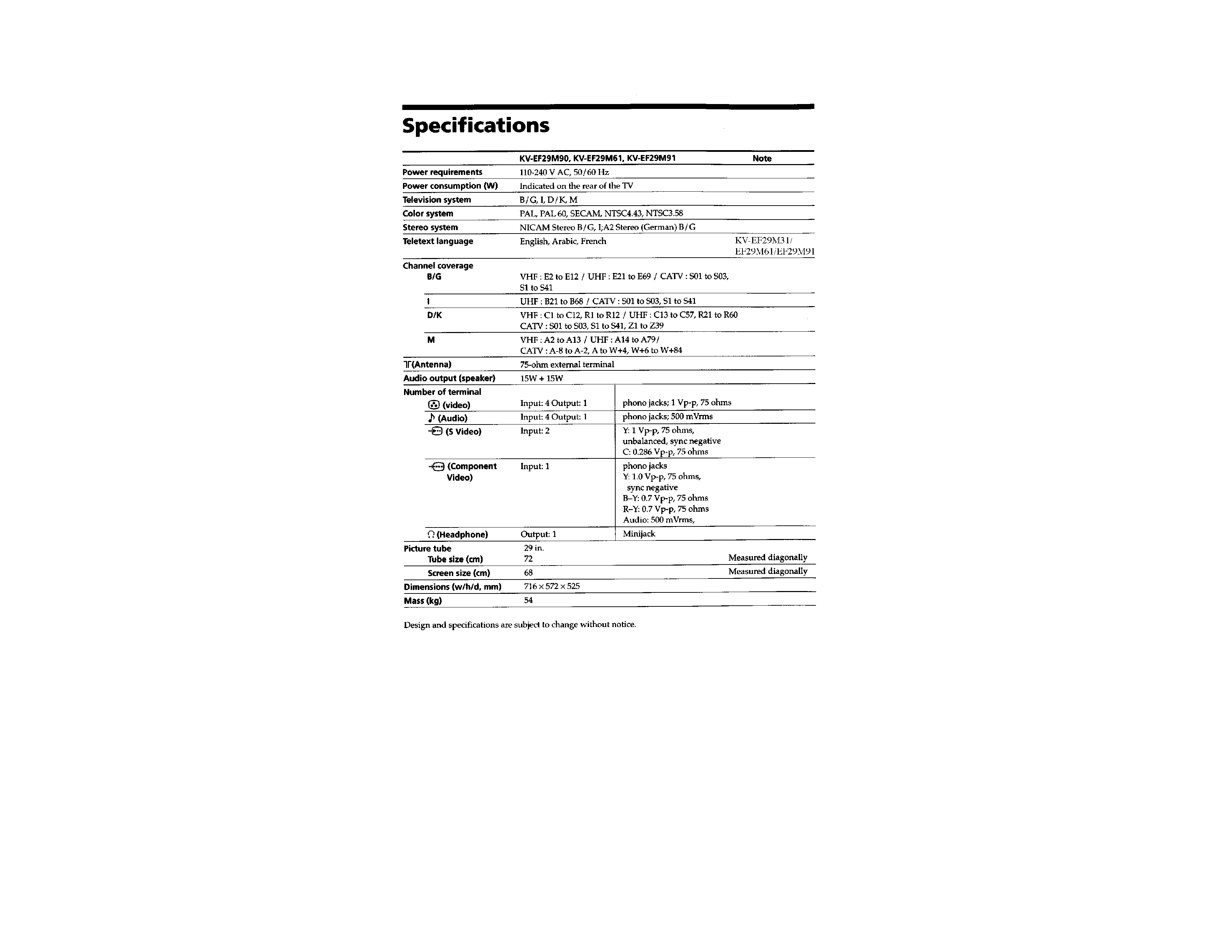
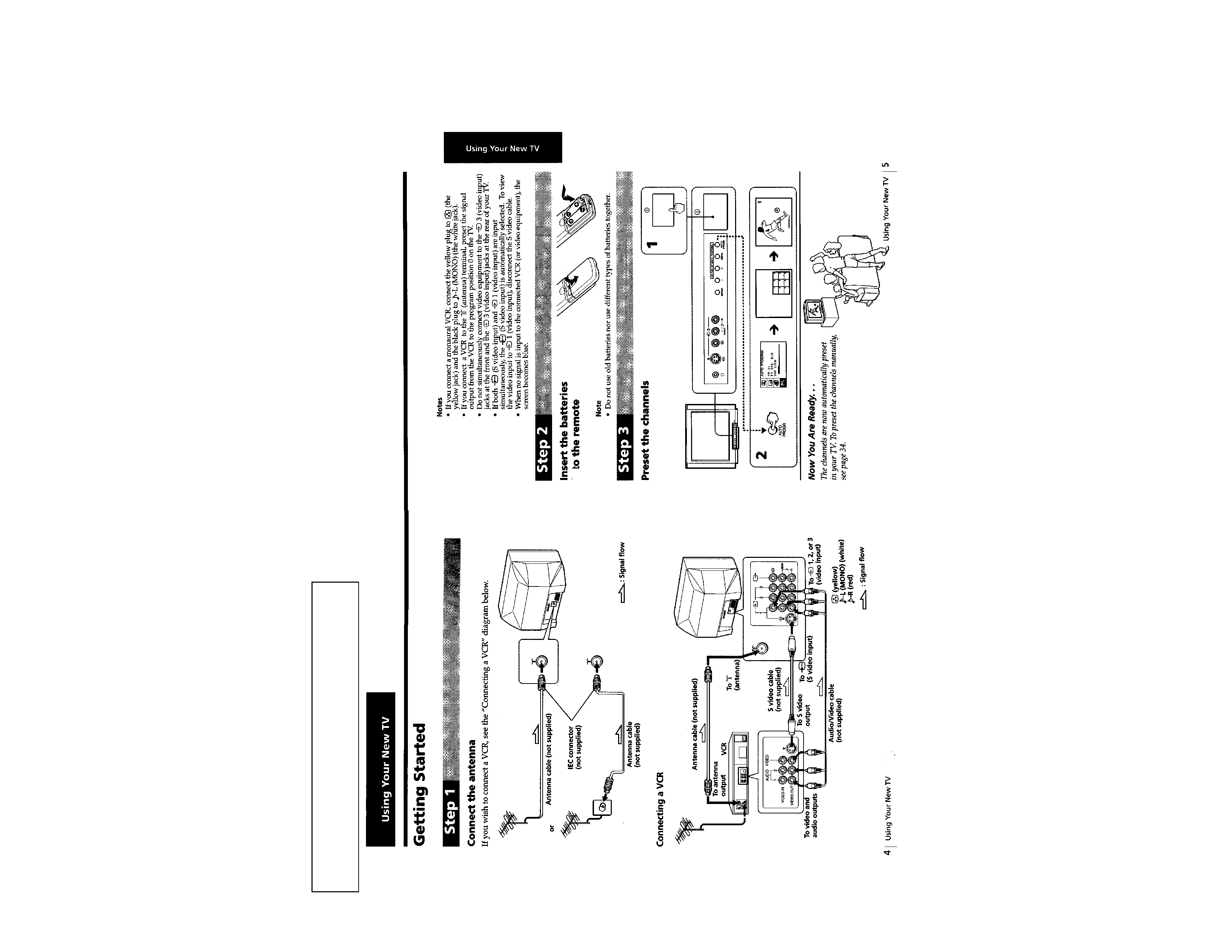
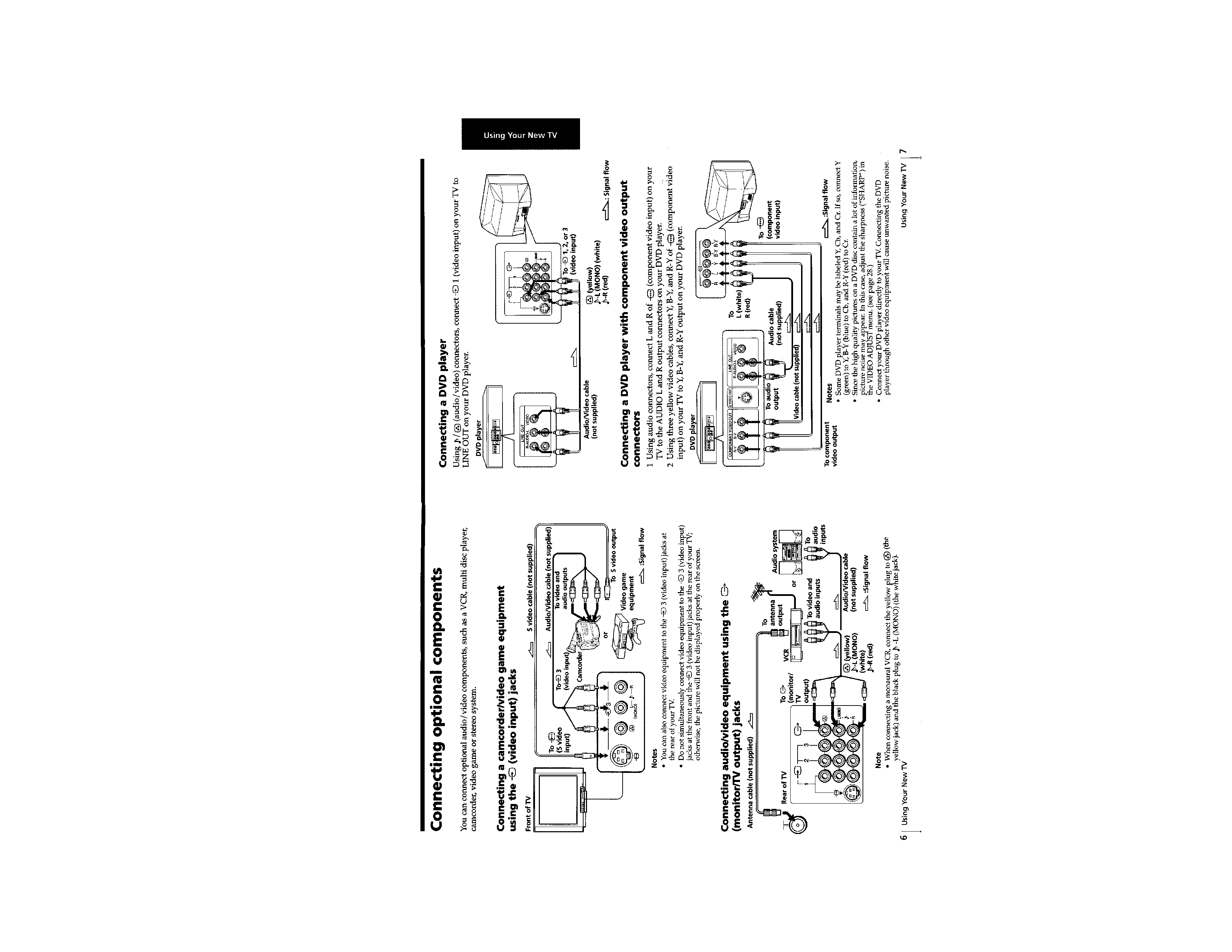
The operating instructions mentioned here are partial abstracts
from the Operating Instruction Manual. The page numbers of
the Operating Instruction Manual remain as in the manual.
MC-Service
5