MODEL
COMMANDER DEST.
CHASSIS NO.
KV-B14K3
RM-849S
Vietnam SCC-H37J-A
SERVICE MANUAL
MODEL
COMMANDER DEST. CHASSIS NO.
CHASSIS
TRINITRON ® COLOR TV
G3E(D)
2
KV-B14K3
RM-849S
SPECIFICATIONS
CAUTION
SHORT CIRCUIT THE ANODE OF THE PICTURE TUBE
AND THE ANODE CAP TO THE METAL CHASSIS, CRT
SHIELD, OR CARBON PAINTED ON THE CRT, AFTER
REMOVING THE ANODE.
SAFETY-RELATED COMPONENT WARNING!!
COMPONENTS IDENTIFIED BY SHADING AND MARK
!
ON THE SCHEMATIC DIAGRAMS, EXPLODED VIEWS
AND IN THE PARTS LIST ARE CRITICAL TO SAFE
OPERATION. REPLACE THESE COMPONENTS WITH
SONY PARTS WHOSE PART NUMBERS APPEAR AS
SHOWN IN THIS MANUAL OR IN SUPPLEMENTS
PUBLISHED BY SONY.
Note
Power requirements
110-240 V AC, 50/60 Hz
Power consumption (W) Indicated on the rear of the TV
Television system
B/G, D/K
Color system
PAL, PAL 60, NTSC4.43, NTSC3.58 (AV IN)
Channel coverage
B/G
VHF: E2 to E12/UHF: E21 to E69/CATV: S01 to S03, S1 to S20
D/K
VHF: R1 to R12/UHF: R21 to R60/CATV: S01 to S03, S1 to S20 to Z39
Audio output (speaker)
5W
Inputs
Antenna: 75 ohms
VIDEO IN jacks: phono jacks
Video: 1 Vp-p, 75 ohms
Audio: 500 mVrms, high impedance
Outputs
Headphone jack: minijack
MONITOR OUT jacks: phono jacks
Video: 1 Vp-p, 75 ohms
Audio: 500 mVrms
Picture tube
14 in.
Tube size (cm)
37
Measured diagonally
Screen size (cm)
34
Measured diagonally
Dimensions (w/h/d, mm) 422
× 350 × 406
Mass (kg)
12
Design and specifications are subject to change without notice.

3
KV-B14K3
RM-849S
TABLE OF CONTENTS
1. GENERAL ....................................................................
4
2. DISASSEMBLY
2-1.
Rear Cover Removal ............................................
8
2-2.
Service Position ...................................................
8
2-3.
Picture Tube Removal ..........................................
8
3. SET-UP ADJUSTMENTS
3-1.
Beam Landing ......................................................
10
3-2.
Convergence .........................................................
11
3-3.
Focus Adjustment ................................................
13
3-4.
Screen (G2) and White Balance Adjustments .....
13
4. CIRCUIT ADJUSTMENTS
4-1.
A Board Adjustments ...........................................
14
5. DIAGRAMS
5-1.
Block Diagrams ....................................................
17
5-2.
Circuit Boards Location .......................................
21
5-3.
Schematic Diagrams and Printed Wiring Boards
(1) Schematic Diagram of A Board ...................... 25
(2) Schematic Diagram of C Board ...................... 29
5-4.
Semiconductors .....................................................
31
6. EXPLODED VIEW
6-1.
Chassis ..................................................................
33
7. ELECTRICAL PARTS LIST ....................................
34
Section
Title
Page
Section
Title
Page
8
KV
-B14K3
RM-849S
SECTION 2
DISASSEMBLY
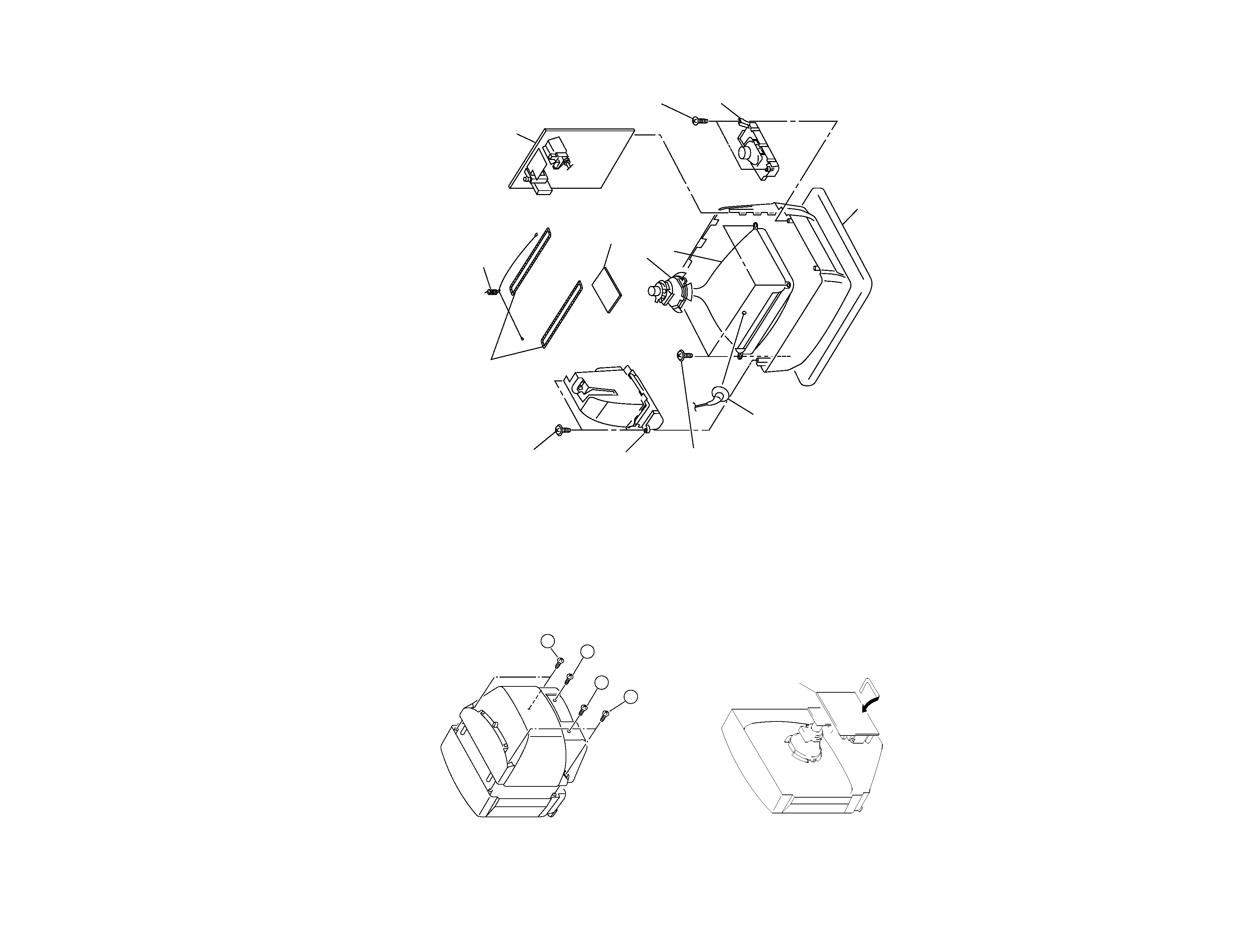
2-1. REAR COVER REMOVAL
2-2. SERVICE POSITION
A board
1 Two screws
(BVTP 4
×16)
3 Two washer head screws
(BVTP 4
×16)
0 Four tapping
screws (5)
4 Speaker
block (L)
2 Speaker
block (R)
9 Tension spring
!TM Degaussing coil
7 C board
5 Anode cap
Cushion
8 Deflection yoke
!¡ Picture tube
6 A board
2-3. PICTURE TUBE REMOVAL
2
Two screws
(BVTP 4
×16)
3
One screw
(BVTP 3
×12)
1 Two screws
(BVTP 4
×16)
4
One screw
(BVTP 3
×12)
9
KV
-B14K3
RM-849S
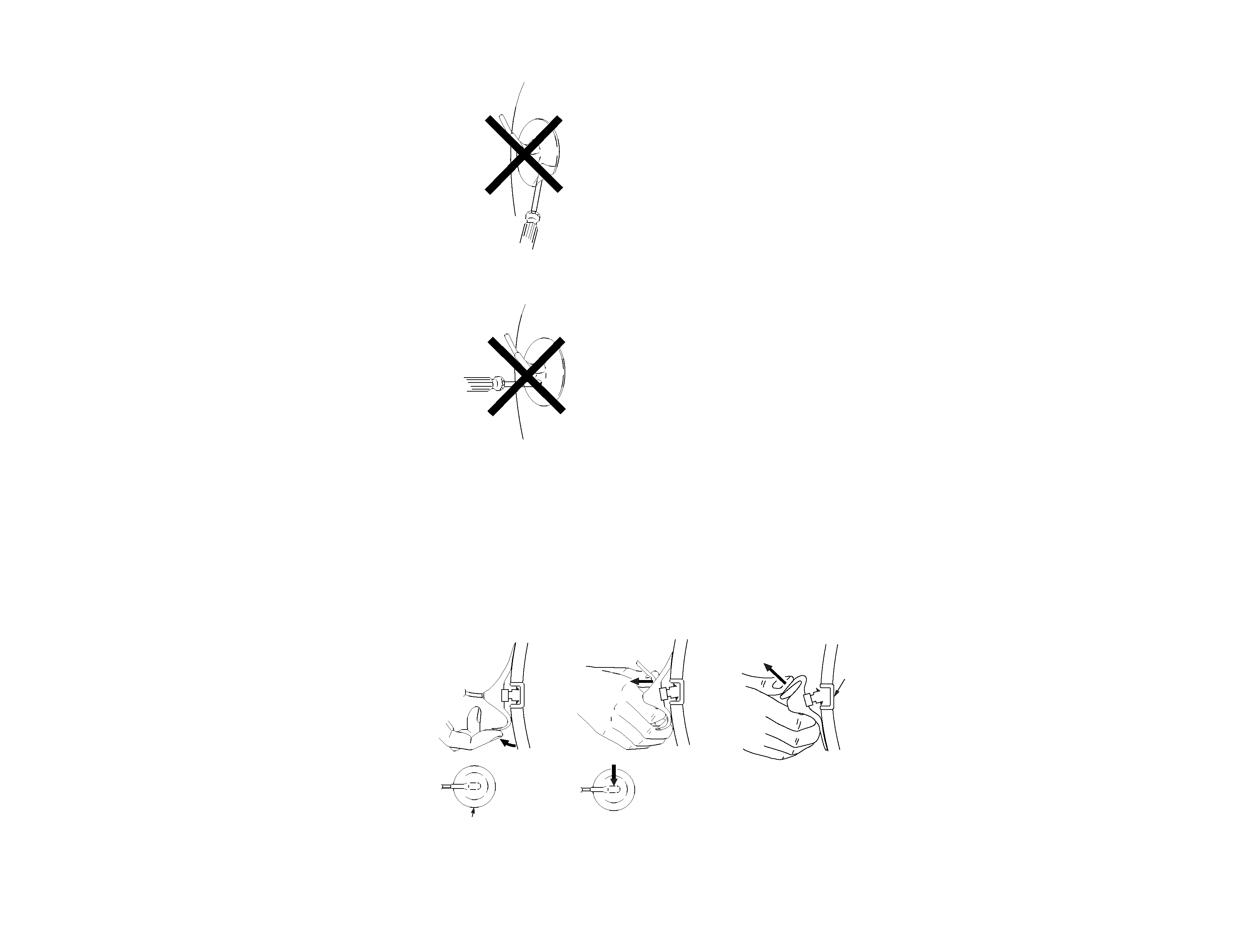
·REMOVAL OF ANODE-CAP
NOTE : After removing the anode, short circuit the anode of the picture tube and the
anode cap to the metal chassis, CRT shield or carbon paint on the CRT.
·REMOVING PROCEDURES
1 Turn up one side of the rubber cap in the direction indicated by the arrow a
3 When one side of the rubber cap is separated from the anode button, the
anode-cap can be removed by turning up the rubber cap and pulling it up in the
direction of the arrow c
2 Using a thumb pull up the rubber cap firmly in the direction indicated by the
arrow b
1 Do not damage the surface of the anode-cap with sharp shaped objects.
2 Do not press the rubber too hard so as not to damage inside of anode-cap.
A metal fitting called the shatter-hook terminal is built into the rubber.
3 Do not turn the foot of rubber over too hard.
The shatter-hook terminal will stick out or damage the rubber.
· HOW TO HANDLE AN ANODE-CAP
a
a
b
b
c
Anode button