
MODEL NAME
DESTINATION
REMOTE COMMANDER
CHASSIS NO.
SERVICE MANUAL
AA-2W CHASSIS
KV-32FS10
U.S.
RM-Y168
SCC-S32B-A
KV-32FS10
CND
RM-Y168
SCC-S33B-A
KV-36FS10
U.S.
RM-Y168
SCC-S32C-A
KV-36FS10
CND
RM-Y168
SCC-S33C-A
KV-36FS10
HAWAII
RM-Y168
SCC-S32HA
KV-32FV15
U.S.
RM-Y171
SCC-S32D-A
KV-32FV15
CND
RM-Y171
SCC-S33D-A
KV-34FV10
E
RM-Y168
SCC-S34E-A
KV-34FV15
E
RM-Y171
SCC-S34F-A
KV-34FV15C
E
RM-Y171
SCC-S34G-A
KV-34FV15K
KOREA
RM-Y149A
SCC-S31B-A
KV-34FV15T
TAIWAN
RM-Y171
SCC-S36A-A
KV-36FV15
U.S.
RM-Y171
SCC-S32G-A
KV-36FV15
CND
RM-Y171
SCC-S33G-A
KV-36FV15
HAWAII
RM-Y171
SCC-S32JA
KV-38FV15K
KOREA
RM-Y149A
SCC-S31C-A
KV-34FX250C
E
RM-Y170
SCC-S34H-A
KV-38FX250
E
RM-Y170
SCC-S34M-A
KV-38FX250C
E
RM-Y170
SCC-S34J-A
KV-38FX250T
TAIWAN
RM-Y170
SCC-S36B-A
KV-32XBR250
U.S.
RM-Y170
SCC-S32E-A
KV-32XBR250
CND
RM-Y170
SCC-S33E-A
KV-36XBR250
U.S.
RM-Y170
SCC-S32F-A
KV-36XBR250
CND
RM-Y170
SCC-S33F-A
KV-36XBR250
HAWAII
RM-Y170
SCC-S32KA
HISTORY INFORMATION FOR THE FOLLOWING MANUAL:
ORIGINAL MANUAL ISSUE DATE: 5/1999
ALL REVISIONS AND UPDATES TO THE ORIGINAL MANUAL ARE APPENDED TO THE END OF THE PDF FILE.
REVISION DATE
REVISION TYPE
SUBJECT
5/1999
No revisions or updates are applicable at this time.
Correction-1
A Board Schematic - Critical Component Identified.
Correction-2
IC002 Part Number Correction
Correction-3
G Board Schematic Correction
Correction-4
Correction to Set-up Adjustments
Correction-5
A Board Schematic Correction
Correction-6
Addition of Hawaiian models; IC001 Part Number Correction;
Addition of ITC Assembly Part Number for Hawaiian models.
Correction-7
Tuner and Terminal labels for rear cover must be ordered separately
using the part numbers provided.
Supplement-1
HZ Board, Picture Tube View, and Electrical Parts List Update
Correction-8
IC643 Part Number Correction
9-965-868-02
-- 1 --
KV-32FS10/32FV15/32XBR250/34FV10/34FV15/34FV15C/34FX250C/34FV15K
34FV15T/36FS10/36FV15/36XBR250/38FX250/38FX250C/38FX250T/38FV15K
TRINITRON® COLOR TV
MODEL
DEST.
COMMANDER
CHASSIS NO.
KV-32FS10
U.S.
RM-Y168
SCC-S32B-A
KV-32FS10
CND
RM-Y168
SCC-S33B-A
KV-36FS10
U.S.
RM-Y168
SCC-S32C-A
KV-36FS10
CND
RM-Y168
SCC-S33C-A
KV-32FV15
U.S.
RM-Y171
SCC-S32D-A
KV-32FV15
CND
RM-Y171
SCC-S33D-A
KV-34FV10
E
RM-Y168
SCC-S34E-A
KV-34FV15
E
RM-Y171
SCC-S34F-A
KV-34FV15C
E
RM-Y171
SCC-S34G-A
KV-34FV15K
KOREA
RM-Y149A
SCC-S31B-A
KV-34FV15T
TAIWAN
RM-Y171
SCC-S36A-A
KV-36FV15
U.S.
RM-Y171
SCC-S32G-A
KV-36FV15
CND
RM-Y171
SCC-S33G-A
KV-38FV15K
KOREA
RM-Y149A
SCC-S31C-A
KV-34FX250C
E
RM-Y170
SCC-S34H-A
KV-38FX250
E
RM-Y170
SCC-S34M-A
KV-38FX250C
E
RM-Y170
SCC-S34J-A
KV-38FX250T
TAIWAN
RM-Y170
SCC-S36B-A
KV-32XBR250
U.S.
RM-Y170
SCC-S32E-A
KV-32XBR250
CND
RM-Y170
SCC-S33E-A
KV-36XBR250
U.S.
RM-Y170
SCC-S32F-A
KV-36XBR250
CND
RM-Y170
SCC-S33F-A
KV-36XBR250
SERVICE MANUAL
CHASSIS
AA-2W
RM-Y170
-- 2 --
KV-32FS10/32FV15/32XBR250/34FV10/34FV15/34FV15C/34FX250C/34FV15K
34FV15T/36FS10/36FV15/36XBR250/38FX250/38FX250C/38FX250T/38FV15K
SPECIFICATIONS
Television system
American TV standard, NTSC
Channel coverage
VHF:2-13 / UHF:14-69 / CATV:1-125
Picture tube
FD Trinitron® tube
Visible screen size
32-inch picture measured diagonally (KV-32FS10, 32FV15,
32XBR250, 34FV10, 34FV15, 34FV15C, 34FV15K,
34FV15T, 34FX250C)
36-inch picture measured diagonally (KV-36FS10, 36FV15,
36XBR250, 38FX250, 38FX250C, 38FX250T, 38FV15K)
Actual screen size
34-inch picture measured diagonally (KV-32FS10,
32FV15, 32XBR250, 34FV10, 34FV15, 34FV15C,
34FV15K, 34FV15T, 34FX250C)
38-inch picture measured diagonally (KV-36FS10, 36FV15,
36XBR250, 38FX250, 38FX250C, 38FX250T, 38FV15K)
Antenna
75 ohm external antenna terminal for VHF/UHF
Supplied accessories
Remote control RM-Y149A (KV-34FV15K, 38FV15K)
Remote control RM-Y168 (KV-32FS10, 34FV10, 36FS10)
Remote control RM-Y170 (KV-32XBR250, 34FX250C,
36XBR250, 38FX250, 38FX250C, 38FX250T)
Remote control RM-Y171 (KV-32FV15, 34FV15, 34FV15C,
34FV15T, 36FV15)
Battery size AA (R6) w/2
Notes:
1)
1 Vp-p 75 ohms unbalanced, sync negative
2) Y: 1 Vp-p 75 ohms unbalanced, sync negative
C: 0.286 Vp-p (Burst signal), 75 ohms
3) Y: 1.0 Vp-p, 75 ohms, sync negative; PB: 0.7 Vp-p, 75 ohms;
PR: Vp-p, 75 ohms
4)
500 mVrms (100% modulation), Impedance: 47 kilohms
5)
More than 408 mVrms at the maximum volume setting (variable)
More than 408 mVrms (fix); Impedance (Output): 2 kilohms
(
) ® SRS (SOUND RETRIEVAL SYSTEM)
The (
) SRS (SOUND RETRIEVAL SYSTEM) is manu-
factured by Sony Corporation under license from SRS Labs,
Inc. It is covered by U.S. Patent No. 4,748,669. Other U.S.
and foreign patents pending.
The word `SRS' and the SRS symbol (
) are registered
trademarks of SRS Labs, Inc.
BBE and BBE symbol are trademarks of BBE Sound, Inc.
and are licensed by BBE Sound, Inc. under U.S. Patent
No. 4,638,258 and 4,482,866.
Optional accessories
Connecting Cables:
RK-74A, VMC-810/820/830HG, VMC-10HG/30HG,
VMC-720M, VMC-810S/820S, YC-15V/30V,
YC-15/30HG, RK-G69HG, RKC-515HG
TV Stand: SU-32FD2, SU-36FD2, SU-32XBR2,
SU-36XBR2
UV Mixer: EAC-66
Design and specifications are subject to change without notice.
**KV-34FV10
**KV-34FV15
**KV-34FV15C
**KV-38FV15K
**KV-34FV15K
*KV-38FX250
**KV-32FV15
**KV-34FV15T
**KV-36FV15
*KV-38FX250C
KV-32FS10
*KV-32XBR250
*KV-34FX250C
KV-36FS10
*KV-36XBR250
*KV-38FX250T
Power Requirements
120V,60Hz
120V,60Hz
120-220V,50/60Hz
120V,60Hz
120V,60Hz
120-220V,50/60Hz
Number of inputs/outputs
Video 1)
33
333
3
S Video 2)
22
222
2
Y, PB, PR 3)
11
111
1
Audio 4)
3
3
3
3
3
3
Audio Out 5)
11
111
1
Monitor Out
1
1
1
1
1
1
TV Out 1) 4)
1
*1/**-
*1/**-
-
*1/**-
*1/**-
S-Link
-
YES
YES
-
YES
YES
Speaker output (W)
10W x 2
15W x 2
15W x 2
10W x 2
15W x 2
15W x 2
Power Consumption (W)
In use (Max)
190W
200W
200W
190W
200W
200W
In Standby
2W
2W
2W
2W
2W
2W
Dimensions (W/H/D)
(mm)
882 x 687 x 592 mm
975 x 757 x 633 mm
(in)
34 3/4 x 27 x 23 1/4 in
38 3/8 x 29 13/16 x 24 15/16 in
Mass
(kg)
80 kg
107 kg
(lbs)
176 lbs
236 lbs
-- 3 --
KV-32FS10/32FV15/32XBR250/34FV10/34FV15/34FV15C/34FX250C/34FV15K
34FV15T/36FS10/36FV15/36XBR250/38FX250/38FX250C/38FX250T/38FV15K
Warnings and Caution ............................................................
3
Safety Check Out Instructions ............................................... 4
1.
GENERAL
Connecting and Installing the TV ............................................ 5
Basic Set Up .......................................................................... 7
Using Your TV ......................................................................... 7
Using the Wireless Headphones ............................................
8
Using Your Menus ................................................................... 9
Operating Video Equipment .................................................... 12
Operating a Cable Box or DBS Receiver ................................ 12
Troubleshooting ...................................................................... 13
2.
DISASSEMBLY
2-1. Rear Cover Removal ....................................................... 14
2-2. Chassis Assembly Removal ............................................ 14
2-3. Service Position ............................................................... 15
2-4. Multi-Button Switch Removal............................................ 15
2-5. Picture Tube Removal ..................................................... 16
3. SET-UP ADJUSTMENTS
3-1. Beam Landing ................................................................. 17
3-2. Convergence ................................................................... 18
3-3. Focus ............................................................................... 20
3-4. Screen (G2) ..................................................................... 20
3-5. White Balance Adjustments ............................................. 20
4. SAFETY RELATED ADJUSTMENTS .................................... 21
5. CIRCUIT ADJUSTMENTS ...................................................... 22
5-1. Method of Setting the Service Adjustment Mode ............. 22
5-2. Memory Write Confirmation Method ................................ 22
5-3. Adjust Buttons and Indicator ............................................ 22
5-4. Service Data .................................................................... 23
TABLE OF CONTENTS
6. DIAGRAMS
6-1. Block Diagram (1/5) ........................................................ 31
6-2. Block Diagram (2/5) ........................................................ 34
6-3. Block Diagram (3/5) ....................................................... 37
6-4. Block Diagram (UY PIP) (4/5) ......................................... 40
6-5. Block Diagram (UX PIP) (5/5) ......................................... 41
6-6. Circuit Boards Location ................................................... 42
6-7. Printed Wiring Boards and Schematic Diagrams ............ 42
·
A Board ...................................................................... 43
·
A Board Schematic Diagram ...................................... 45
·
AK Board .......................... ......................................... 49
·
C Board ...................................................................... 53
·
G Board ...................................................................... 55
·
GA Board .................................................................... 57
·
HA Board .................................................................... 57
·
HB Board .................................................................... 57
·
HX Board .................................................................... 59
·
T Board ....................................................................... 59
·
UX Main Board ........................................................... 61
·
UX PIP Board ............................................................. 65
·
UY Main Board .......................................................... 69
·
UY PIP Board ............................................................ 73
·
WA Board ................................................................... 75
6-8. Semiconductors .............................................................. 77
7. EXPLODED VlEWS
7-1. Chassis ........................................................................... 78
7-2. Chassis ........................................................................... 80
7-3. Picture Tube .................................................................... 81
8. ELECTRICAL PARTS LIST
·
Parts Listings .............................................................. 83
CAUTION!
AFTER REMOVING THE ANODE, SHORT CIRCUIT THE ANODE
OF THE PICTURE TUBE AND THE ANODE CAP TO THE METAL
CHASSIS, CRT SHIELD, OR CARBON PAINTED ON THE CRT.
WARNING!!
AN ISOLATION TRANSFORMER SHOULD BE USED DURING ANY
SERVICE TO AVOID POSSIBLE SHOCK HAZARD, BECAUSE OF
LIVE CHASSIS. THE CHASSIS OF THIS RECEIVER IS DIRECTLY
CONNECTED TO THE AC POWER LINE.
SAFETY-RELATED COMPONENT WARNING!!
COMPONENTS IDENTIFIED BY SHADING AND MARK
¡ ON
THE SCHEMATIC DIAGRAMS, EXPLODED VIEWS AND IN THE
PARTS LIST ARE CRITICAL FOR SAFE OPERATION. REPLACE
THESE COMPONENTS WITH SONY PARTS WHOSE PART
NUMBERS APPEAR AS SHOWN IN THIS MANUAL OR IN
SUPPLEMENTS
PUBLISHED
BY
SONY.
CIRCUIT
ADJUSTMENTS THAT ARE CRITICAL FOR SAFE OPERATION
ARE IDENTIFIED IN THIS MANUAL. FOLLOW THESE
PROCEDURES WHENEVER CRITICAL COMPONENTS ARE
REPLACED OR IMPROPER OPERATION IS SUSPECTED.
ATTENTION!
APRES AVOIR DECONNECTE LE CAP DE L'ANODE, COURT-CIRCUITER L'ANODE
DU TUBE CATHODIQUE ET CELUI DE L'ANODE DU CAP AU CHASSIS METALLIQUE
DE L'APPAREIL, OU AU COUCHE DE CARBONE PEINTE SUR LE TUBE CATHODIQUE
OU AU BLINDAGE DU TUBE CATHODIQUE.
ATTENTION!!
AFIN D'EVITER TOUT RESQUE D'ELECTROCUTION PROVENANT D'UN CHÁSSIS
SOUS TENSION, UN TRANSFORMATEUR D'ISOLEMENT DOIT ETRE UTILISÉ LORS
DE TOUT DÉPANNAGE. LE CHÁSSIS DE CE RÉCEPTEUR EST DIRECTEMENT
RACCORDÉ À L'ALIMENTATION SECTEUR.
ATTENTION AUX COMPOSANTS RELATIFS A LA SECURITE!!
LES COMPOSANTS IDENTIFIES PAR UNE TRAME ET PAR UNE MARQUE ¡ SUR
LES SCHEMAS DE PRINCIPE, LES VUES EXPLOSEES ET LES LISTES DE PIECES
SONT D'UNEIMPORTANCE CRITIQUE POUR LA SECURITE DU FONCTIONNEMENT.
NE LES REMPLACER QUE PAR DES COMPOSANTS SONY DONT LE NUMERO DE
PIECE EST INDIQUE DANS LE PRESENT MANUEL OU DANS DES SUPPLEMENTS
PUBLIES PAR SONY. LES REGLAGES DE CIRCUIT DONT L'IMPORTANCE EST CRI-
TIQUE POUR LA SECURITE DU FONCTIONNEMENT SONT IDENTIFIES DANS LE
PRESENT MANUEL. SUIVRE CES PROCEDURES LORS DE CHAQUE
REMPLACEMENT DE COMPOSANTS CRITIQUES, OU LORSQU'UN MAUVAIS
FONTIONNEMENT SUSPECTE.
WARNINGS AND CAUTIONS
Section
Title
Page
Section
Title
Page
-- 4 --
KV-32FS10/32FV15/32XBR250/34FV10/34FV15/34FV15C/34FX250C/34FV15K
34FV15T/36FS10/36FV15/36XBR250/38FX250/38FX250C/38FX250T/38FV15K
SAFETY CHECK-OUT
After correcting the original service problem, perform the
following safety checks before releasing the set to the
customer:
LEAKAGE TEST
The AC leakage from any exposed metal part to earth ground and
from all exposed metal parts to any exposed metal part having a
return to chassis, must not exceed 0.5 mA (500 microampere).
Leakage current can be measured by any one of three methods.
1. A commercial leakage tester, such as the Simpson 229 or
RCA WT-540A. Follow the manufacturers' instructions to
use these instructions.
2. A battery-operated AC milliammeter. The Data Precision
245 digital multimeter is suitable for this job.
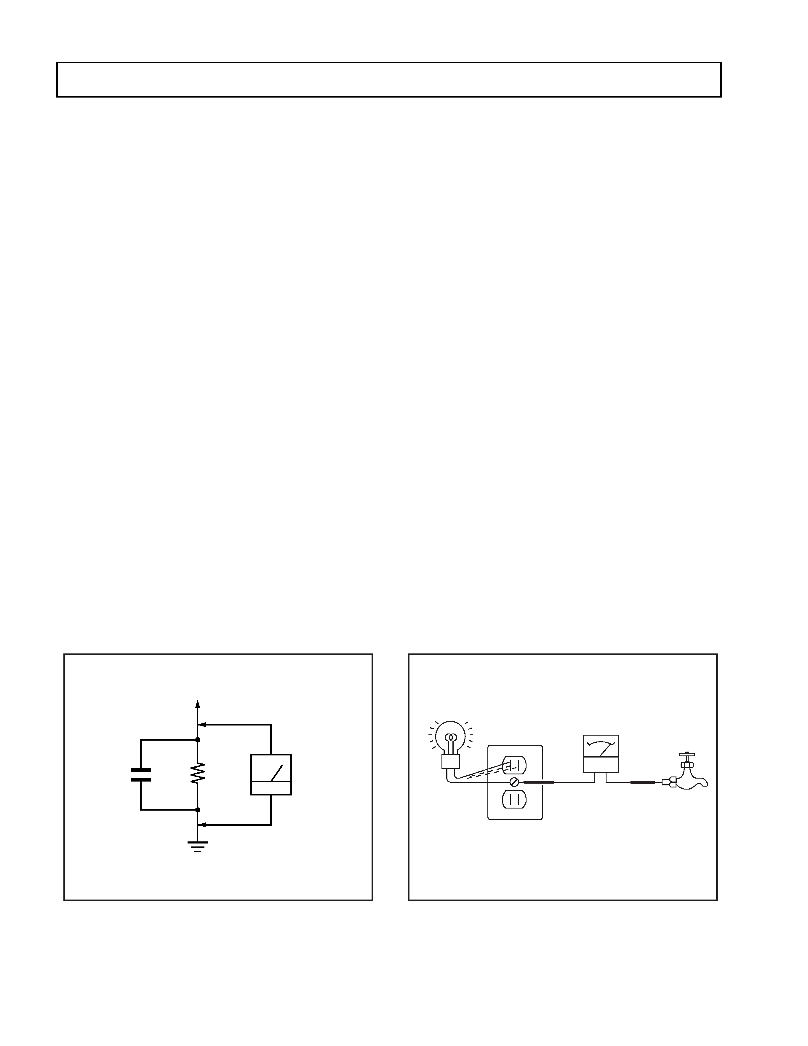
3. Measuring the voltage drop across a resistor by means of
a VOM or battery-operated AC voltmeter. The "limit"
indication is 0.75 V, so analog meters must have an accurate
low voltage scale. The Simpson's 250 and Sanwa
SH-63Trd are examples of passive VOMs that are suitable.
Nearly all battery operated digital multimeters that have a
2V AC range are suitable. (See Fig. A)
1. Check the area of your repair for unsoldered or poorly-
soldered connections. Check the entire board surface
for solder splashes and bridges.
2. Check the interboard wiring to ensure that no wires
are "pinched" or contact high-wattage resistors.
3. Check that all control knobs, shields, covers, ground
straps, and mounting hardware have been replaced.
Be absolutely certain that you have replaced all the
insulators.
4. Look for unauthorized replacement parts, particularly
transistors, that were installed during a previous
repair. Point them out to the customer and
recommend their replacement.
5. Look for parts which, though functioning, show
obvious signs of deterioration. Point them out to
the customer and recommend their replacement.
6. Check the line cords for cracks and abrasion.
Recommend the replacement of any such line cord
to the customer.
7. Check the B+ and HV to see if they are specified
values. Make sure your instruments are accurate;
be suspicious of your HV meter if sets always have
low HV.
8. Check the antenna terminals, metal trim, "metallized"
knobs, screws, and all other exposed metal parts for
AC Leakage. Check leakage as described below.
HOW TO FIND A GOOD EARTH GROUND
A cold-water pipe is guaranteed earth ground; the cover-plate
retaining screw on most AC outlet boxes is also at earth ground.
If the retaining screw is to be used as your earth-ground, verify
that it is at ground by measuring the resistance between it and a
cold-water pipe with an ohmmeter. The reading should be zero
ohms. If a cold-water pipe is not accessible, connect a 60-l00 watts
trouble light (not a neon lamp) between the hot side of the re-
ceptacle and the retaining screw. Try both slots, if necessary, to
locate the hot side of the line, the lamp should light at normal
brilliance if the screw is at ground potential. (See Fig. B)
To Exposed Metal
Parts on Set
Fig. A. Using an AC voltmeter to check AC leakage.
Fig. B. Checking for earth ground.
Cold-water Pipe
Ohmmeter
AC Outlet Box
Trouble Light
Earth Ground
0.15 F
µ
1.5 k
AC
Voltmeter
(0.75 V)