
1
SERVICE MANUAL
BE-3ECHASSIS
MODEL
COMMANDER
DEST
CHASSIS NO.
KV-28FS20U
RM-887
UK
SCC-Q25G-A
MODEL
COMMANDER
DEST
CHASSIS NO.

2
TABLE OF CONTENTS
Section
Title
Page
Section
Title
Page
Specifications
....................
3
Connectors
....................
4
Self Diagnostic Software
....................
5
1. GENERAL
Overview of the Remote Control...................
9
AutomaticallyTuning the TV
....................
9
Rearranging the TV Channels ....................
10
Adjusting the Picture
....................
10
Adjusting the Sound
....................
11
Setting up Dolby Pro Logic
....................
11
Changing the Screen Mode
....................
12
Choosing a Language
....................
12
ManuallyTuning the TV
....................
13
Teletext
....................
13
Specifications
....................
14
Troubleshooting
....................
14
2. DISASSEMBLY
2-1.
Rear Cover Removal
....................
15
2-2.
Chassis Assy Removal
....................
15
2-3.1
Service Position (1)
....................
15
2-3.2
Service Position (2)
....................
15
2-4.
Wire Dressing
....................
16
2-5.
A Board Removal
....................
16
2-6.
A Extension Board
....................
16
2-7.
Picture Tube Removal
....................
17
Bottom Plates
....................
18
3. SET-UP ADJUSTMENTS
3-1.
Beam Landing
....................
19
3-2.
Convergence
....................
20
3-3.
Screen (G2), White Balance
...................
22
3-4.
Focus Adjustment
....................
22
3-5.
White Balance
....................
23
.
4. CIRCUIT ADJUSTMENTS
4-1.
Electrical Adjustments
....................
24
4-2.
TT Test Mode
....................
27
4-3.
T Test Mode
....................
28
5. DIAGRAMS
5-1.
Block Diagram (1)
....................
29
Block Diagram (2)
....................
31
Block Diagram (3)
....................
33
Block Diagram (4)
....................
35
5-2.
Circuit Board Location
....................
36
5-3.
Schematic Diagrams and
Printed Wiring Boards
....................
37
* C Board
....................
37
* D Board
....................
39
* A1 Board
....................
44
* J1 Board
....................
45
* VM Board
....................
47
* J2 Board
....................
49
* D2 Board
....................
50
* D1 Board
....................
51
* A Board
....................
54
* H Board
....................
63
5-4.
Semiconductors
....................
67
5-5.
IC Blocks
....................
69
6. EXPLODED VIEWS
6-1.
Chassis
....................
71
6-2.
Picture Tube
....................
72
7. ELECTRICAL PARTS LIST
....................
73
CAUTION
SHORT CIRCUIT THE ANODE OF THE PICTURE TUBE AND THE
ANODE CAP TO THE METAL CHASSIS, CRT SHIELD, OR THE
CARBON PAINTED ON THE CRT, AFTER REMOVAL OF THE
ANODE CAP.
WARNING !!
AN ISOLATION TRANSFORMER SHOULD BE USED DURING ANY
SERVICE WORK TO AVOID POSSIBLE SHOCK HAZARD DUE TO
LIVE CHASSIS, THE CHASSIS OF THIS RECEIVER IS DIRECTLY
CONNECTED TO THE POWER LINE.
SAFETY-RELATED COMPONENT WARNING !!
COMPONENTS IDENTIFIED BY SHADING AND MARKED
£ ON
THE SCHEMATIC DIAGRAMS, EXPLODED VIEWS AND IN THE
PARTS LIST ARE CRITICAL FOR SAFE OPERATION. REPLACE
THESE COMPONENTS WITH SONY PARTS WHOSE PART
NUMBERS APPEAR AS SHOWN IN THIS MANUAL OR IN
SUPPLEMENTS PUBLISHED BY SONY.
ATTENTION
APRES AVOIR DECONNECTE LE CAP DE'LANODE,
COURT-CIRCUITER L'ANODE DU TUBE CATHODIQUE ET CELUI
DE L'ANODE DU CAP AU CHASSIS METALLIQUE DE L'APPAREIL,
OU AU COUCHE DE CARBONE PEINTE SUR LE TUBE
CATHODIQUE OU AU BLINDAGE DU TUBE CATHODIQUE.
ATTENTION !!
AFIN D'EVITER TOUT RISQUE D'ELECTROCUTION PROVENANT
D'UN CHÁSSIS SOUS TENTION, UN TRANSFORMATEUR
D'ISOLEMENT DOIT ETRE UTILISÈ LORS DE TOUT DÈPANNAGE
LE CHÁSSIS DE CE RÈCEPTEUR EST DIRECTMENT RACCORDÈ
Á L'ALIMENTATION SECTEUR.
ATTENTION AUX COMPOSANTS RELATIFS Á
LA SECURITÈ!!
LES COMPOSANTS IDENTIFIÈS PAR UNE TRAME ET PAR UNE
MARQUE
£ SUR LES SCHÈMAS DE PRINCIPE, LES VUES
EXPLOSÈES ET LES LISTES DE PIECES SONT D'UNE IMPOR-
TANCE CRITIQUE POUR LA SÈCURITÈ DU FONCTIONNEMENT,
NE LES REMPLACER QUE PAR DES COMPSANTS SONY DONT LE
NUMÈRO DE PIÈCE EST INDIQUÈ DANS LE PRÈSENT MANUEL
OU DANS DES SUPPLÈMENTS PUBLIÈS PAR SONY.
3
WARNING (UK Models only)
The flexible mains lead is supplied connected to a B.S. 1363 fused plug
having a fuse of 13 AMP rating. Should the fuse need to be replaced,
use a 13 AMP FUSE approved by ASTA to BS 1362, ie one that
carries the ASA
T mark.
IF THE PLUG SUPPLIED WITH THIS APPLIANCE IS NOT SUITABLE
FOR THE OUTLET SOCKETS IN YOUR HOME, IT SHOULD BE CUT
OFF AND AN APPROPRIATE PLUG FITTED. THE PLUG SEVERED
FROM THE MAINS LEAD MUST BE DESTROYED AS A PLUG WITH
BARED WIRES IS DANGEROUS IF ENGAGED IN A LIVE SOCKET.
When an alternative type of plug is used, it should be fitted with a
13 AMP FUSE, otherwise the circuit should be protected by a 13 AMP
FUSE at the distribution board.
How to replace the fuse.
Open the fuse compartment with
a screwdriver blade and replace
the fuse.
FUSE
l
e
d
o
M
U
0
2
S
F
8
2
n
o
i
t
p
m
u
s
n
o
C
r
e
w
o
PW
3
2
1
L
E
D
O
M
M
E
T
I
m
e
t
s
y
S
n
o
i
s
i
v
e
l
e
T
m
e
t
s
y
S
o
e
r
e
t
S
e
g
a
r
e
v
o
C
l
e
n
n
a
h
C
m
e
t
s
y
S
r
o
l
o
C
K
UI
o
e
r
e
t
S
M
A
C
I
N9
6
B
-
1
2
B
:
F
H
U
,
3
4
.
4
C
S
T
N
,
L
A
P
)
N
I
O
E
D
I
V
(
8
5
.
3
C
S
T
N
e
b
u
T
e
r
u
t
c
i
P
e
d
i
W
n
o
r
t
i
n
i
r
T
D
F
)
s
e
h
c
n
i
8
2
(
m
c
1
7
x
o
r
p
p
A
d
e
r
u
s
a
e
m
e
r
u
t
c
i
p
m
c
6
6
x
o
r
p
p
A
(
)
y
ll
a
n
o
g
a
i
d
2
0
1
0
n
o
i
t
c
e
l
f
e
d
t
u
p
t
u
o
d
n
u
o
S
r
e
k
a
e
p
s
t
f
e
L
d
n
a
t
h
g
i
R
r
e
f
o
o
W
b
u
S
r
e
k
a
e
p
s
e
r
t
n
e
C
d
n
u
o
r
r
u
S
)
r
e
w
o
P
c
i
s
u
M
(
W
0
2
x
2
)
r
e
w
o
P
c
i
s
u
M
(
W
0
2
)
r
e
w
o
P
c
i
s
u
M
(
W
0
1
x
1
)
r
e
w
o
P
c
i
s
u
M
(
W
5
x
2
]
R
A
E
R
[
s
l
a
n
i
m
r
e
T
t
u
p
t
u
O
/
t
u
p
n
I
s
t
n
e
m
e
r
i
u
q
e
R
r
e
w
o
PV
0
4
2
-
0
2
2
r
o
t
c
e
n
n
o
c
o
r
u
E
n
i
p
-
1
2
:
1
)
d
r
a
d
n
a
t
s
C
E
L
E
N
E
C
(
.
s
l
a
n
g
i
s
o
e
d
i
V
d
n
a
o
i
d
u
A
r
o
f
s
t
u
p
n
I
.
B
G
R
r
o
f
s
t
u
p
n
I
o
i
d
u
A
d
n
a
o
e
d
i
V
V
T
f
o
s
t
u
p
t
u
O
.
s
l
a
n
g
i
s
s
n
o
i
s
n
e
m
i
Dm
m
5
2
5
x
6
9
4
x
1
6
7
x
o
r
p
p
A
r
o
t
c
e
n
n
o
c
o
r
u
E
n
i
p
-
1
2
:
2
)
d
r
a
d
n
a
t
s
C
E
L
E
N
E
C
(
.
s
l
a
n
g
i
s
o
e
d
i
V
d
n
a
o
i
d
u
A
r
o
f
s
t
u
p
n
I
.
o
e
d
i
V
S
r
o
f
s
t
u
p
n
I
o
i
d
u
A
d
n
a
o
e
d
i
V
r
o
t
i
n
o
M
f
o
s
t
u
p
t
u
O
)
e
l
b
a
t
c
e
l
e
s
(
.
s
l
a
n
g
i
s
t
h
g
i
e
Wg
k
4
4
x
o
r
p
p
A
s
k
c
a
J
o
n
o
h
P
s
l
a
n
g
i
S
o
i
d
u
A
r
o
f
s
r
o
t
c
e
n
n
o
C
t
u
p
t
u
O
s
e
i
r
o
s
s
e
c
c
A
d
e
il
p
p
u
S
)
1
(
r
e
d
n
a
m
m
o
C
e
t
o
m
e
R
7
8
8
-
M
R
)
2
(
y
r
e
t
t
a
b
6
R
d
e
t
a
n
g
i
s
e
d
C
E
I
)
1
(
r
e
k
a
e
p
S
e
r
t
n
e
C
)
2
(
s
r
e
k
a
e
p
S
d
n
u
o
r
r
u
S
s
l
a
n
i
m
r
e
t
r
e
k
a
e
p
s
l
a
n
r
e
t
x
E)
5
(
N
I
D
n
i
p
2
s
e
r
u
t
a
e
F
r
e
h
t
Ok
n
il
t
r
a
m
S
,
d
n
u
o
r
r
u
S
y
b
l
o
D
,
t
x
e
t
e
l
e
T
]
T
N
O
R
F
[
s
l
a
n
i
m
r
e
T
t
u
p
t
u
O
/
t
u
p
n
I
7
8
8
-
M
R
k
c
a
j
e
n
o
h
p
d
a
e
Hk
c
a
j
i
n
i
m
o
e
r
e
t
s
m
e
t
s
y
s
l
o
r
t
n
o
c
e
t
o
m
e
Rl
o
r
t
n
o
c
d
e
r
a
r
f
n
I
s
t
u
p
n
i
o
i
d
u
As
k
c
a
j
o
n
o
h
p
s
t
n
e
m
e
r
i
u
q
e
r
r
e
w
o
P
c
d
V
3
n
o
i
t
a
n
g
i
s
e
d
C
E
I
s
e
i
r
e
t
t
a
b
2
)
A
A
e
z
i
s
(
6
R
t
u
p
t
u
o
o
e
d
i
Vk
c
a
j
o
n
o
h
p
s
n
o
i
s
n
e
m
i
D)
d
/
h
/
w
(
m
m
3
2
x
4
4
x
9
0
2
x
o
r
p
p
A
t
u
p
n
i
o
e
d
i
V
SN
I
D
n
i
p
4
t
h
g
i
e
W)
y
r
e
t
t
a
b
g
n
i
d
u
l
c
n
i
t
o
n
(
g
9
8
x
o
r
p
p
A
.
e
c
i
t
o
n
t
u
o
h
t
i
w
e
g
n
a
h
c
o
t
t
c
e
j
b
u
s
e
r
a
s
n
o
i
t
a
c
i
f
i
c
e
p
s
d
n
a
n
g
i
s
e
D
e
m
a
N
l
e
d
o
M
m
e
t
I
U
0
2
S
F
8
2
-
V
K
b
m
o
C
l
a
PF
F
O
P
I
PF
F
O
y
t
i
r
o
i
r
P
B
G
RF
F
O
x
o
B
r
e
f
o
o
WN
O
1
t
r
a
c
SN
O
2
t
r
a
c
SN
O
)
3
(
n
i
t
n
o
r
FN
O
4
t
r
a
c
SF
F
O
r
o
t
c
e
j
o
r
PF
F
O
e
d
o
m
9
:
6
1
n
i
B
K
AN
O
G
/
B
m
r
o
NF
F
O
I
m
r
o
NN
O
K
/
D
m
r
o
NF
F
O
S
U
A
m
r
o
NF
F
O
L
m
r
o
NF
F
O
T
A
S
m
r
o
NF
F
O
M
m
r
o
NF
F
O
t
x
e
t
e
l
e
TN
O
o
e
r
e
t
S
m
a
c
i
NN
O
t
e
s
e
r
P
e
g
a
u
g
n
a
Lh
s
il
g
n
E
4
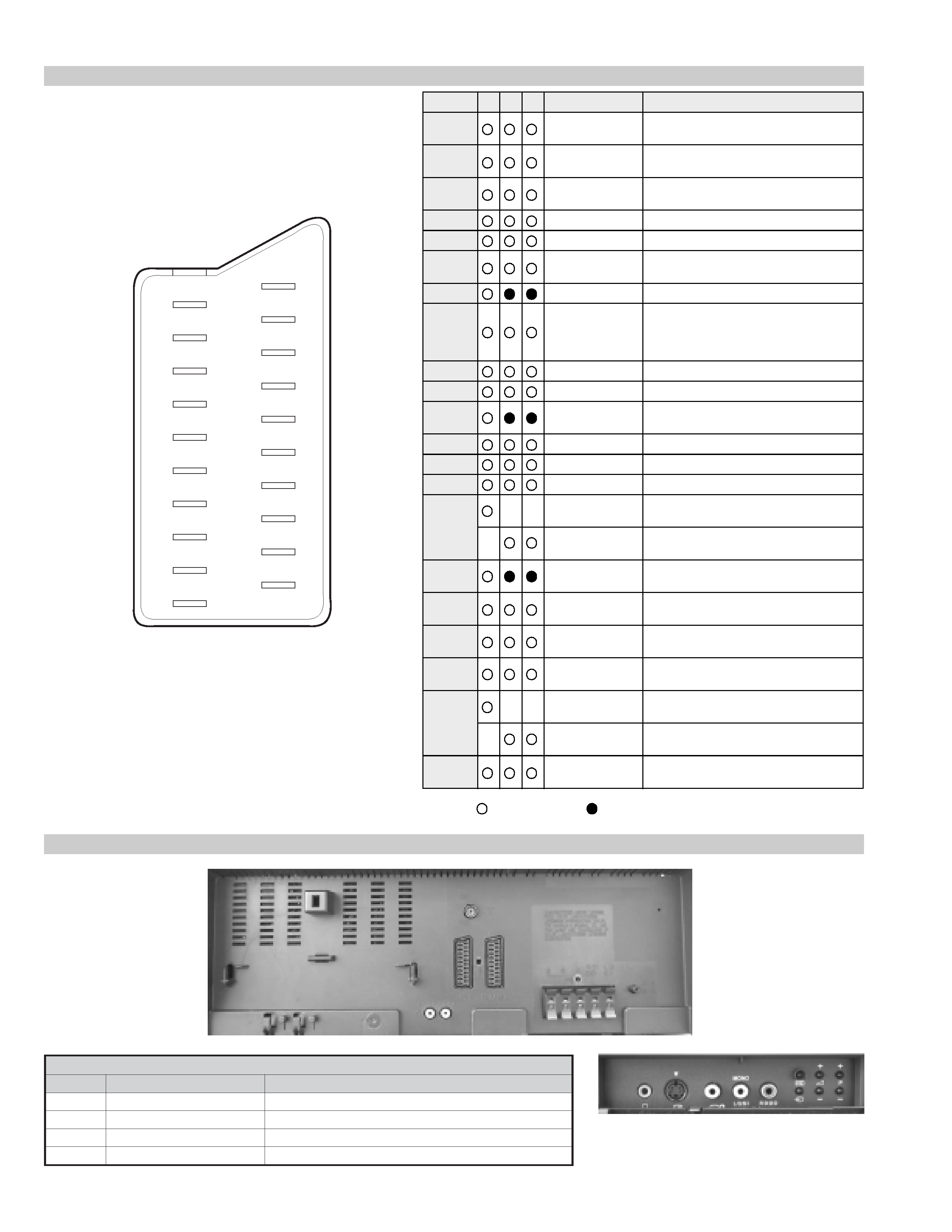
21 pin connector
Connected
Not Connected (open)
* at 20Hz - 20kHz
Pin No
1
2
4
Signal
Signal level
1
Audio output B
(right)
Standard level : 0.5V rms
Output impedence : Less than 1kohm*
2
Audio output B
(right)
Standard level : 0.5V rms
Output impedence : More than 10kohm*
3
Audio output A
(left)
Standard level : 0.5V rms
Output impedence : Less than 1kohm*
4
Ground (audio)
5
Ground (blue)
6
Audio input A
(left)
Standard level : 0.5V rms
Output impedence : More than 10kohm*
7
Blue input
0.7 +/- 3dB, 75 ohms positive
8
Function select
(AV control)
High state (9.5-12V) : Part mode
Low state (0-2V) : TV mode
Input impedence : More than 10K ohms
Input capacitance : Less than 2nF
9
Ground (green)
10
Open
11
Green
Green signal : 0.7 +/- 3dB, 75 ohms,
positive
12
Open
13
Ground (red)
14
Ground (blanking)
15
_
_
Red input
0.7 +/- 3dB, 75 ohms, positive
_
(S signal Chroma
input)
0.3 +/- 3dB, 75 ohms, positive
16
Blanking input
(Ys signal)
High state (1-3V) Low state (0-0.4V)
Input impedence : 75 ohms
17
Ground (video
output)
18
Ground (video
input)
19
Video output
1V +/- 3dB, 75ohms, positive sync 0.3V
(-3+10dB)
20
_
_
Video input
1V +/- 3dB, 75ohms, positive sync 0.3V
(-3+10dB)
_
Video input
Y (S signal)
1V +/- 3dB, 75ohms, positive sync 0.3V
(-3+10dB)
21
Common ground
(plug, shield)
19
17
15
13
11
9
7
5
3
1
20
18
16
14
12
10
8
6
4
2
21
Rear Connection Panel
n
o
i
t
a
r
u
g
i
f
n
o
c
n
i
p
t
e
k
c
o
s
o
e
d
i
V
S
o
N
n
i
P
l
a
n
g
i
S
l
e
v
e
L
l
a
n
g
i
S
1d
n
u
o
r
G-
2d
n
u
o
r
G-
3t
u
p
n
i
)
l
a
n
g
i
s
S
(
Y
B
d
0
1
+
3
-
V
3
.
0
.
c
n
y
S
e
v
i
t
i
s
o
p
,
m
h
o
5
7
B
d
3
-
/
+
V
1
4t
u
p
n
i
)
l
a
n
g
i
s
S
(
C.
c
n
y
S
e
v
i
t
i
s
o
p
,
m
h
o
5
7
B
d
3
-
/
+
V
3
.
0
S-Video
socket

5
BE-3E SELF DIAGNOSTIC SOFTWARE
The errors indicated below can be read using an Error Reader Display (Part Number S-188-900-10) connected to the service connector. Once an
error has been detected it will then be displayed on the two digit error reader. During the power up procedure and during normal run time, the
micro's self diagnostic procedures monitor for various errors. Errors displayed refer to the table indicated below.
Error Number
Error Description
00
No error (TV Error Reader shows 00 in normal condition)
01
Not allowed (may be confused with Sircs response flash on LED)
02
Protection circuit trip (OCP, OVP & No V-Sync)
03
Reserved for OVP (Included in error 2 for BE-3E)
04
Reserved for No V-Sync (Included in error 2 for BE-3E)
05
AKB
06
IIC Scl Low <Power Up only>
07
IIC Sda Low <Power Up only>
08
IIC Sda & Scl Low <Power Up only>
09
Jungle controller no acknowledge <Power Up only>
10
Video Switch (CXA2040) no acknowledge <Power Up only>
11
Tuner no acknowledge
12
MSP no acknowledge
13
NVM no acknowledge
14
AV switch (CXA2089) no acknowledge (DS20 & DX20)
15
Not used
16
Port Expander (CXA1875) no acknowledge (DS20 & DX20)
17
Not used
18
Dynamic Convergence (CXA8070) no acknowledge
19
Cannot Initialise jungle (after initial power on check OK) - <Chassis Initialisation>
20
Jungle controller response failure after power up check (+9V test)
21
Video Switch (CXA2040) cannot power on reset - <Chassis Initialisation>
22
Video Switch (CXA2040) response failiure after power up check (+9V test)
23
NVM acknowledge fail after initialisation (STBY +5V - same as micro!)
24
MSP run-time failure <May Not Be Fatal - Display On Error Reader>
25
DSP run-time failure <May Not Be Fatal - Display On Error Reader>
26
M3L bus Clock low time out after data send <Run-Time Failure>
27
M3L bus Clock low time out after data send <At Power Up Check>
28
M3L bus Clock low time out after data send <At Initialisation>
29
M3L Txd Low <Power Up Only>
30
M3L Rxd Low <Power Up Only>
31
M3L Enable Low <Power Up Only>
32
Compact Text test fail <Power Up Only>
33
Compact Text does not respond (+5V test)
34
Compact text run-time failure <May Not Be Fatal - Display On Error Reader>