
1
SERVICE MANUAL
AE-5 CHASSIS
MODEL
COMMANDER
DEST
CHASSIS NO.
KV-28FC60
RM-892
Europe
SCC-Q11K-A
KV-28FC60/Z
RM-892
Europe
SCC-Q11J-A
MODEL
COMMANDER
DEST
CHASSIS NO.
KV-32FC60
RM-892
Europe
SCC-Q11G-A
KV-32FC60/Z
RM-892
Europe
SCC-Q11H-A

2
l
e
d
o
M
0
6
C
F
8
2
Z
/
0
6
C
F
8
2
0
6
C
F
2
3
Z
/
0
6
C
F
2
3
n
o
i
t
p
m
u
s
n
o
C
r
e
w
o
PW
2
3
1W
2
3
1W
0
3
1W
0
3
1
e
b
u
T
e
r
u
t
c
i
P
n
o
r
t
i
n
i
r
T
D
F
)
s
e
h
c
n
i
8
2
(
m
c
1
7
x
o
r
p
p
A
d
e
r
u
s
a
e
m
e
r
u
t
c
i
p
m
c
6
6
x
o
r
p
p
A
(
)
y
ll
a
n
o
g
a
i
d
)
s
e
h
c
n
i
2
3
(
m
c
2
8
x
o
r
p
p
A
d
e
r
u
s
a
e
m
e
r
u
t
c
i
p
m
c
6
7
x
o
r
p
p
A
(
)
y
ll
a
n
o
g
a
i
d
n
o
i
t
c
e
l
f
e
d
e
e
r
g
e
d
0
1
1
t
u
p
t
u
o
d
n
u
o
S
r
e
f
o
o
w
b
u
S
r
e
k
a
e
p
s
t
f
e
L
d
n
a
t
h
g
i
R
)
r
e
w
o
P
c
i
s
u
M
(
W
5
2
x
2
)
S
M
R
(
W
5
1
x
2
]
R
A
E
R
[
s
l
a
n
i
m
r
e
T
t
u
p
t
u
O
/
t
u
p
n
I
s
t
n
e
m
e
r
i
u
q
e
R
r
e
w
o
PV
0
4
2
-
0
2
2
r
o
t
c
e
n
n
o
c
o
r
u
E
n
i
p
-
1
2
:
1
)
d
r
a
d
n
a
t
s
C
E
L
E
N
E
C
(
.
s
l
a
n
g
i
s
o
e
d
i
V
d
n
a
o
i
d
u
A
r
o
f
s
t
u
p
n
I
.
B
G
R
r
o
f
s
t
u
p
n
I
o
i
d
u
A
d
n
a
o
e
d
i
V
V
T
f
o
s
t
u
p
t
u
O
.
s
l
a
n
g
i
s
s
n
o
i
s
n
e
m
i
D
m
m
)
d
(
3
3
5
x
)
h
(
7
9
4
x
)
w
(
2
7
7
"
8
2
m
m
)
d
(
8
5
5
x
)
h
(
4
6
5
x
)
w
(
7
6
8
"
2
3
r
o
t
c
e
n
n
o
c
o
r
u
E
n
i
p
-
1
2
:
2
.
s
l
a
n
g
i
s
o
e
d
i
V
d
n
a
o
i
d
u
A
r
o
f
s
t
u
p
n
I
.
o
e
d
i
V
S
r
o
f
s
t
u
p
n
I
.
s
l
a
n
g
i
s
o
i
d
u
A
d
n
a
o
e
d
i
V
V
T
f
o
s
t
u
p
t
u
O
)
e
l
b
a
t
c
e
l
e
s
(
t
h
g
i
e
W
g
k
5
.
2
4
x
o
r
p
p
A
"
8
2
g
k
5
6
x
o
r
p
p
A
"
2
3
r
o
t
c
e
n
n
o
c
o
r
u
E
n
i
p
-
1
2
:
3
.
s
l
a
n
g
i
s
o
e
d
i
V
d
n
a
o
i
d
u
A
r
o
f
s
t
u
p
n
I
.
o
e
d
i
V
S
r
o
f
s
t
u
p
n
I
s
l
a
n
g
i
s
o
e
d
i
V
/
o
i
d
u
A
f
o
s
t
u
p
t
u
O
)
t
u
o
r
o
t
i
n
o
m
(
s
e
i
r
o
s
s
e
c
c
A
d
e
il
p
p
u
S
)
1
(
r
e
d
n
a
m
m
o
C
e
t
o
m
e
R
2
9
8
-
M
R
)
2
(
y
r
e
t
t
a
b
6
R
d
e
t
a
n
g
i
s
e
d
C
E
I
s
k
c
a
J
A
C
Rs
l
a
n
g
i
S
o
i
d
u
A
r
o
f
t
u
p
t
u
O
s
e
r
u
t
a
e
F
r
e
h
t
O
,
w
e
i
V
T
x
e
N
,
o
e
r
e
t
s
M
A
C
I
N
r
e
t
li
F
b
m
o
C
l
a
t
i
g
i
D
e
r
u
t
c
i
P
z
H
0
0
1
r
e
s
il
a
u
q
E
c
i
h
p
a
r
G
s
l
a
n
i
m
r
e
t
r
e
k
a
e
p
s
l
a
n
r
e
t
x
EN
I
D
n
i
p
2
t
u
p
n
i
o
e
d
i
V
SN
I
D
n
i
p
4
2
9
8
-
M
R
]
T
N
O
R
F
[
s
l
a
n
i
m
r
e
T
t
u
p
t
u
O
/
t
u
p
n
I
m
e
t
s
y
s
l
o
r
t
n
o
c
e
t
o
m
e
Rl
o
r
t
n
o
c
d
e
r
a
r
f
n
I
k
c
a
j
e
n
o
h
p
d
a
e
Hk
c
a
ji
n
i
m
o
e
r
e
t
s
s
t
n
e
m
e
r
i
u
q
e
r
r
e
w
o
P
c
d
V
3
n
o
i
t
a
n
g
i
s
e
d
C
E
I
s
e
i
r
e
t
t
a
b
2
)
A
A
e
z
i
s
(
6
R
s
n
o
i
s
n
e
m
i
D)
d
/
h
/
w
(
m
m
3
2
x
5
5
x
0
1
2
x
o
r
p
p
A
t
h
g
i
e
W)
y
r
e
t
t
a
b
g
n
i
d
u
l
c
n
i
t
o
n
(
g
0
1
1
x
o
r
p
p
A
.
e
c
i
t
o
n
t
u
o
h
t
i
w
e
g
n
a
h
c
o
t
t
c
e
j
b
u
s
e
r
a
s
n
o
i
t
a
c
i
f
i
c
e
p
s
d
n
a
n
g
i
s
e
D
L
E
D
O
M
M
E
T
I
m
e
t
s
y
S
n
o
i
s
i
v
e
l
e
T
m
e
t
s
y
S
o
e
r
e
t
S
e
g
a
r
e
v
o
C
l
e
n
n
a
h
C
m
e
t
s
y
S
r
o
l
o
C
P
E
AI
,
L
,
K
/
D
,
H
/
G
/
B
M
A
C
I
N
/
N
A
M
R
E
G
o
e
r
e
t
S
0
6
F
-
1
2
F
:
F
H
U
0
1
F
-
2
0
F
:
F
H
V
L
2
1
E
-
2
E
:
F
H
V
H
/
G
/
B
Q
-
B
:
E
L
B
A
C
9
6
E
-
1
2
E
:
F
H
U
1
4
S
-
1
S
:
)
1
(
V
T
E
L
B
A
C
0
1
U
-
1
U
,
0
1
M
-
1
M
,
5
0
S
-
1
0
S
:
)
2
(
V
T
E
L
B
A
C
9
6
-
1
2
:
F
H
U
)
C
(
2
H
-
A
:
F
H
V
A
I
L
A
T
I
9
6
B
-
1
2
B
:
F
H
U
I
M
A
C
E
S
,
L
A
P
8
5
.
3
C
S
T
N
,
3
4
.
4
C
S
T
N
)
N
I
O
E
D
I
V
(

3
WARNING (UK Models only)
The flexible mains lead is supplied connected to a B.S. 1363 fused
plug having a fuse of 5 AMP rating. Should the fuse need to be
replaced, use a 5 AMP FUSE approved by ASTA to BS 1362, ie one
that carries the ASA
T mark.
IF THE PLUG SUPPLIED WITH THIS APPLIANCE IS NOT SUITABLE
FOR THE OUTLET SOCKETS IN YOUR HOME, IT SHOULD BE CUT
OFF AND AN APPROPRIATE PLUG FITTED. THE PLUG SEVERED
FROM THE MAINS LEAD MUST BE DESTROYED AS A PLUG WITH
BARED WIRES IS DANGEROUS IF ENGAGED IN A LIVE SOCKET.
When an alternative type of plug is used, it should be fitted with a
5 AMP FUSE, otherwise the circuit should be protected by a 5 AMP
FUSE at the distribution board.
How to replace the fuse.
Open the fuse compartment with
a screwdriver blade and replace
the fuse.
FUSE
e
m
a
N
l
e
d
o
M
m
e
t
I
0
6
C
F
8
2
-
V
K
Z
/
0
6
C
F
8
2
-
V
K
0
6
C
F
2
3
-
V
K
Z
0
6
C
F
2
3
-
V
K
b
m
o
C
l
a
PN
ON
ON
ON
O
P
I
PF
F
OF
F
OF
F
OF
F
O
y
t
i
r
o
i
r
P
B
G
RN
ON
ON
ON
O
x
o
B
r
e
f
o
o
WN
ON
ON
ON
O
1
t
r
a
c
SN
ON
ON
ON
O
2
t
r
a
c
SN
ON
ON
ON
O
)
3
(
n
i
r
a
e
R
p
o
TN
ON
ON
ON
O
4
t
r
a
c
SN
ON
ON
ON
O
r
o
t
c
e
j
o
r
PF
F
OF
F
OF
F
OF
F
O
e
d
o
m
9
:
6
1
n
i
B
K
AN
ON
ON
ON
O
G
/
B
m
r
o
NN
ON
ON
ON
O
I
m
r
o
NN
ON
ON
ON
O
K
/
D
m
r
o
NN
ON
ON
ON
O
S
U
A
m
r
o
NF
F
OF
F
OF
F
OF
F
O
L
m
r
o
NN
ON
ON
ON
O
T
A
S
m
r
o
NF
F
OF
F
OF
F
OF
F
O
M
m
r
o
NF
F
OF
F
OF
F
OF
F
O
t
x
e
t
e
l
e
TN
ON
ON
ON
O
o
e
r
e
t
S
m
a
c
i
NN
ON
ON
ON
O
4
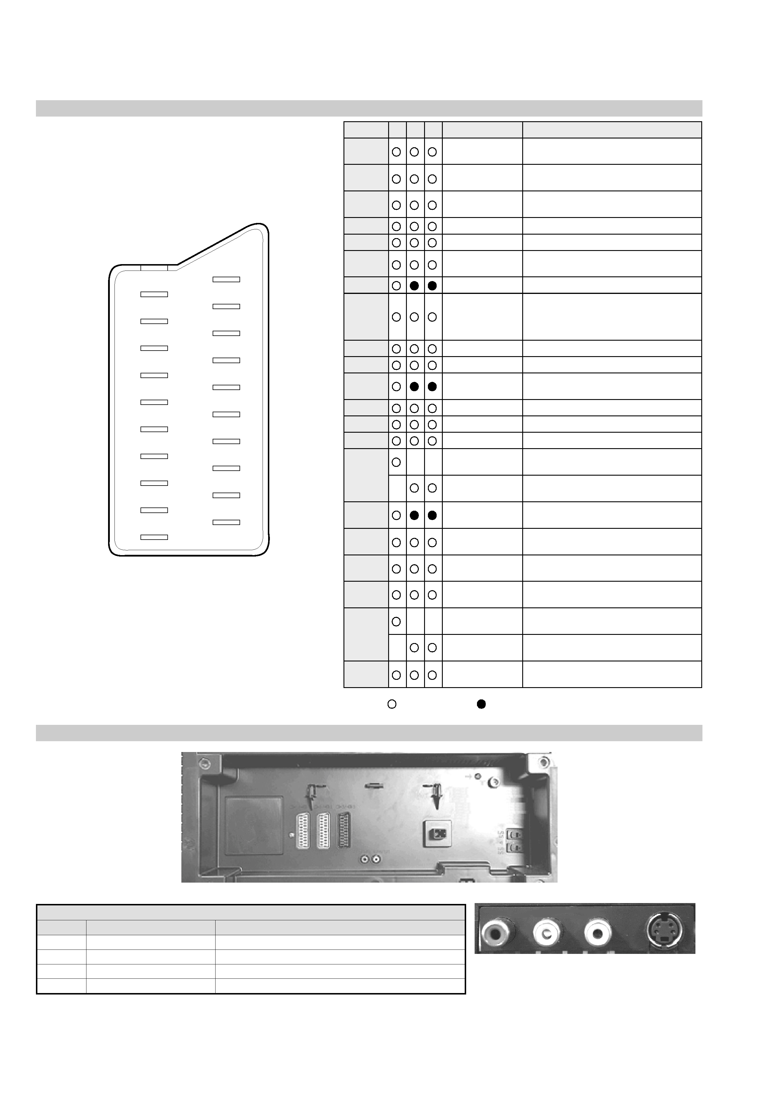
21 pin connector
Connected
Not Connected (open)
* at 20Hz - 20kHz
Pin No
1
2
4
Signal
Signal level
1
Audio output B
(right)
Standard level : 0.5V rms
Output impedence : Less than 1kohm*
2
Audio output B
(right)
Standard level : 0.5V rms
Output impedence : More than 10kohm*
3
Audio output A
(left)
Standard level : 0.5V rms
Output impedence : Less than 1kohm*
4
Ground (audio)
5
Ground (blue)
6
Audio input A
(left)
Standard level : 0.5V rms
Output impedence : More than 10kohm*
7
Blue input
0.7 +/- 3dB, 75 ohms positive
8
Function select
(AV control)
High state (9.5-12V) : Part mode
Low state (0-2V) : TV mode
Input impedence : More than 10K ohms
Input capacitance : Less than 2nF
9
Ground (green)
10
Open
11
Green
Green signal : 0.7 +/- 3dB, 75 ohms,
positive
12
Open
13
Ground (red)
14
Ground (blanking)
15
_
_
Red input
0.7 +/- 3dB, 75 ohms, positive
_
(S signal Chroma
input)
0.3 +/- 3dB, 75 ohms, positive
16
Blanking input
(Ys signal)
High state (1-3V) Low state (0-0.4V)
Input impedence : 75 ohms
17
Ground (video
output)
18
Ground (video
input)
19
Video output
1V +/- 3dB, 75ohms, positive sync 0.3V
(-3+10dB)
20
_
_
Video input
1V +/- 3dB, 75ohms, positive sync 0.3V
(-3+10dB)
_
Video input
Y (S signal)
1V +/- 3dB, 75ohms, positive sync 0.3V
(-3+10dB)
21
Common ground
(plug, shield)
19
17
15
13
11
9
7
5
3
1
20
18
16
14
12
10
8
6
4
2
21
Rear Connection Panel
n
o
i
t
a
r
u
g
i
f
n
o
c
n
i
p
t
e
k
c
o
s
o
e
d
i
V
S
o
N
n
i
P
l
a
n
g
i
S
l
e
v
e
L
l
a
n
g
i
S
1d
n
u
o
r
G-
2d
n
u
o
r
G-
3t
u
p
n
i
)
l
a
n
g
i
s
S
(
Y
B
d
0
1
+
3
-
V
3
.
0
.
c
n
y
S
e
v
i
t
i
s
o
p
,
m
h
o
5
7
B
d
3
-
/
+
V
1
4t
u
p
n
i
)
l
a
n
g
i
s
S
(
C.
c
n
y
S
e
v
i
t
i
s
o
p
,
m
h
o
5
7
B
d
3
-
/
+
V
3
.
0
S-Video
socket
5
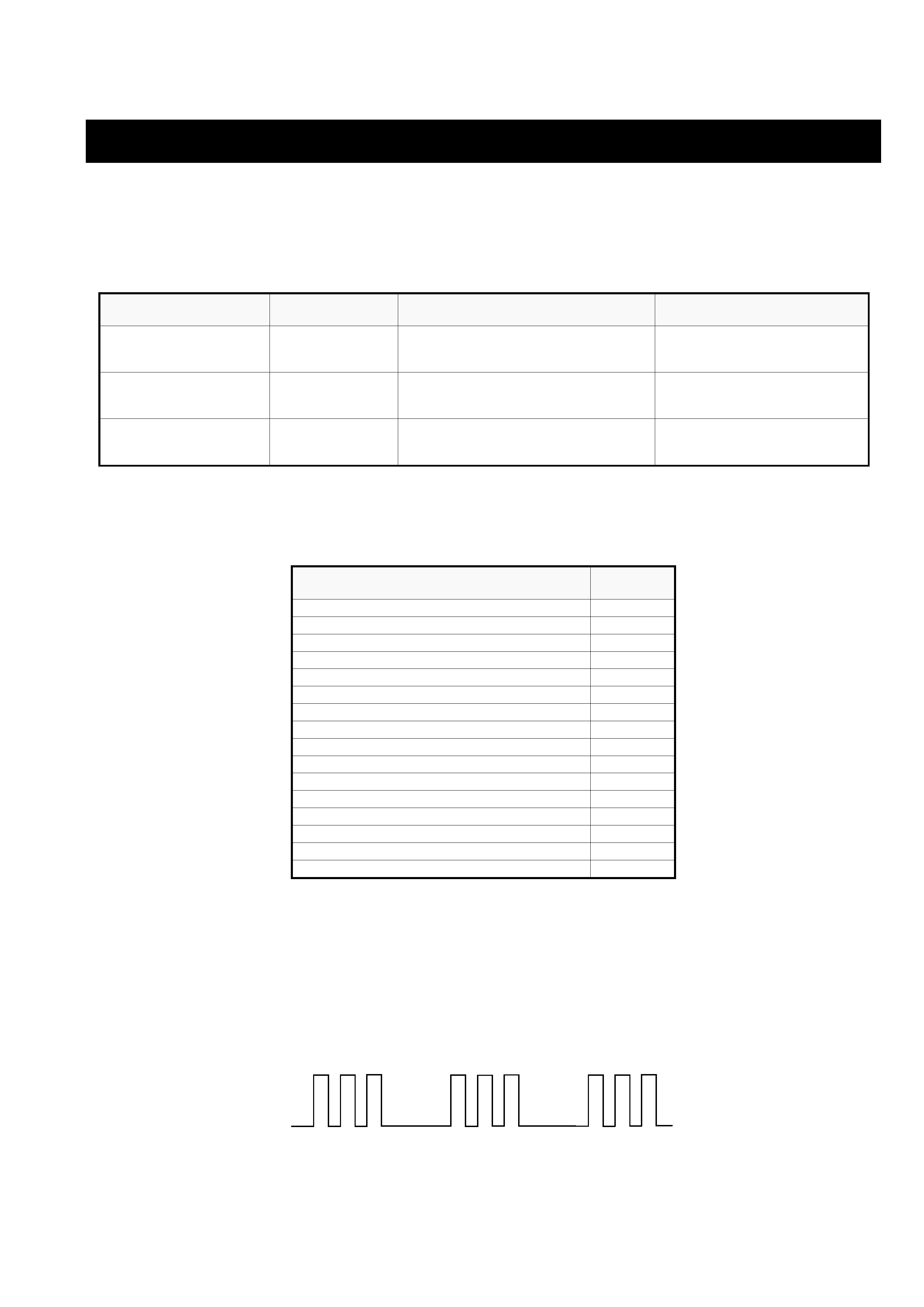
AE-5 SELF DIAGNOSTIC SOFTWARE
The identification of errors within the AE-5 chassis is triggered in one of two ways :- 1: Busy or 2: Device failure to respond to IIC. In the event
of one of these situations arising the software will first try to release the bus if busy (Failure to do so will report with a continuous flashing LED)
and then communicate with each device in turn to establish if a device is faulty. If a device is found to be faulty the relevant device number will
be displayed through the LED (Series of flashes which must be counted) See table 1., non fatal errors are reported using this method.
m
e
t
I
c
i
t
s
o
n
g
a
i
D
n
o
i
t
p
i
r
c
s
e
D
y
b
d
n
a
t
S
s
e
m
i
t
f
o
o
N
s
e
h
s
a
l
F
D
E
L
e
s
u
a
c
e
l
b
a
b
o
r
P
n
o
i
t
a
c
o
L
s
m
o
t
p
m
y
S
d
e
t
c
e
t
e
D
n
o
n
r
u
t
t
o
n
s
e
o
d
r
e
w
o
Pt
h
g
il
t
o
n
s
e
o
D
.
n
i
d
e
g
g
u
l
p
t
o
n
s
i
d
r
o
c
r
e
w
o
P
.
t
i
u
c
r
i
c
n
e
p
o
s
i
e
s
u
F
n
o
e
m
o
c
t
o
n
s
e
o
d
r
e
w
o
P
V
T
e
h
t
o
t
d
e
il
p
p
u
s
s
i
r
e
w
o
p
o
N
y
t
l
u
a
f
s
i
y
l
p
p
u
s
r
e
w
o
p
C
A
)
P
C
O
(
t
n
e
r
r
u
c
r
e
v
O
B
+s
e
m
i
t
2
)
d
r
a
o
B
D
(
.
d
e
t
r
o
h
s
s
i
)
4
0
8
6
/
3
0
8
6
Q
(
T
U
O
.
H
)
d
r
a
o
B
D
(
.
d
e
t
r
o
h
s
s
i
)
6
0
8
6
Q
(
T
E
F
y
t
i
r
a
e
n
i
L
)
d
r
a
o
B
D
(
.
d
e
t
r
o
h
s
s
i
C
I
r
e
w
o
P
4
0
6
6
C
I
n
o
e
m
o
c
t
o
n
s
e
o
d
r
e
w
o
P
d
e
t
r
o
h
s
s
a
h
e
n
il
r
e
w
o
p
n
o
d
a
o
L
d
e
p
p
o
t
s
n
o
i
t
c
e
l
f
e
D
l
a
c
i
t
r
e
Vs
e
m
i
t
4
)
d
r
a
o
B
D
(
n
e
p
o
5
3
8
6
R
d
e
il
p
p
u
s
t
o
n
s
i
V
5
1
+
)
d
r
a
o
B
D
(
n
e
p
o
4
3
8
6
R
d
e
il
p
p
u
s
t
o
n
s
i
V
5
1
-
)
d
r
a
o
B
D
(
d
e
t
r
o
h
s
s
i
0
0
7
6
C
I
d
e
p
p
o
t
s
s
a
h
e
s
l
u
p
n
o
i
t
c
e
l
f
e
d
l
a
c
i
t
r
e
V
d
e
t
r
o
h
s
s
a
h
e
n
il
r
e
w
o
P
Flash Timing Example : e.g. error number 3
StBy LED
ON
ON
ON
OFF
OFF
e
g
a
s
s
e
M
r
o
r
r
E
D
E
L
e
d
o
C
r
o
r
r
e
o
N0
0
r
o
r
r
e
s
u
b
C
2
I1
0
)
n
o
i
t
c
e
t
o
r
P
t
n
e
r
r
u
C
r
e
v
O
(
P
C
O2
0
)
n
o
i
t
c
e
t
o
r
P
e
g
a
t
l
o
V
r
e
v
O
(
P
V
O3
0
n
o
i
t
c
e
t
o
r
P
l
a
c
i
t
r
e
V4
0
d
e
v
r
e
s
e
R5
0
n
o
i
t
c
e
t
o
r
P
l
a
t
n
o
z
i
r
o
H6
0
n
o
i
t
c
e
t
o
r
P
r
e
k
a
e
p
S7
0
r
e
d
o
c
e
D
t
x
e
t
e
l
e
T
.
B
-
M8
0
M
V
N
,
2
3
C
4
2
T
S
.
B
-
M9
0
r
e
d
o
c
e
D
r
u
o
l
o
C
n
i
a
M
,
0
2
3
9
A
D
T
,
B
-
J0
1
x
o
B
e
r
u
t
a
e
F
,
B
-
2
B
/
1
B1
1
r
e
t
r
e
v
n
o
C
A
/
D
,
B
-
1
B2
1
d
n
e
k
c
a
B
.
B
-
E3
1
r
o
s
s
e
c
o
r
P
d
n
u
o
S
,
D
0
1
4
3
P
S
M
.
B
-
J4
1
e
d
i
W
o
t
u
A
,
7
5
0
2
D
X
C
.
B
-
J5
1