
SERVICE MANUAL
BA-6 CHASSIS
TRINITRON
® COLOR TELEVISION
MODEL NAME
REMOTE COMMANDER
DESTINATION
CHASSIS NO.
9-965-938-04
KV-21FA210
RM-Y180
LATIN NORTH
SCC-S60P-A
KV-21FA210
RM-Y180
LATIN SOUTH
SCC-S60Q-A
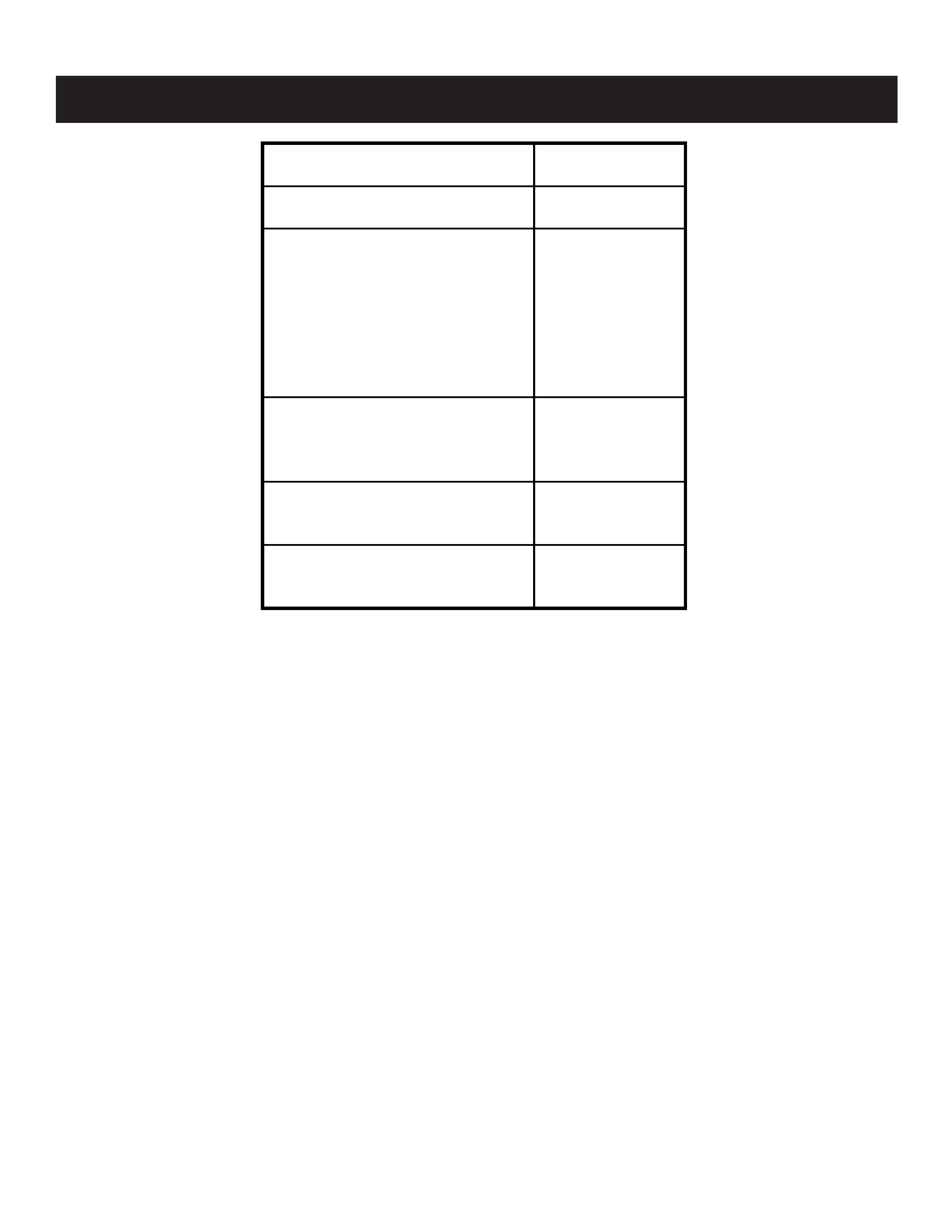
HISTORY INFORMATION FOR THE FOLLOWING MANUAL:
ORIGINAL MANUAL ISSUE DATE: 3/2003
:UPDATED ITEM
REVISION DATE
SUBJECT
3/2003
No revisions or updates are applicable at this time.
4/2003
Replaced A Board Transistor Voltage List (Q600, Q601) (Replace Page 34)
Replaced A Board IC Voltage List (IC600) (Replace Page 35)
9/2003
Added assembly P/N for Woofer Assembly (Replace Page 43)
11/2003
Replaced A Board Schematic to correct T603 PIN Connection (Replace Page 31)
SERVICE MANUAL
BA-6CHASSIS
TRINITRON® COLOR TELEVISION
MODEL NAME
REMOTE COMMANDER
DESTINATION
CHASSIS NO.
9-965-938-04
KV-21FA210
RM-Y180
LATIN NORTH
SCC-S60P-A
KV-21FA210
RM-Y180
LATIN SOUTH
SCC-S60Q-A
Self Diagnosis
Supported model
KV-21FA210
RM-Y180

-- 3 --
KV-21FA210
TABLE OF CONTENTS
SECTION TITLE
PAGE
Specifications ............................................................................................................................................................................. 4
Warnings and Cautions .............................................................................................................................................................. 5
Safety Check-Out ....................................................................................................................................................................... 6
Self-Diagnostic Function............................................................................................................................................................. 7
SECTION 1: DISASSEMBLY............................................................................................................................................................. 9
1-1. Rear Cover Removal.......................................................................................................................................................... 9
1-2. Chassis Assembly Removal............................................................................................................................................... 9
1-3. Service Position ................................................................................................................................................................. 9
1-4. Picture Tube Removal...................................................................................................................................................... 10
Anode Cap Removal Procedure....................................................................................................................................... 10
SECTION 2: SET-UP ADJUSTMENTS.............................................................................................................................................11
2-1. Beam Landing...................................................................................................................................................................11
2-2. Convergence.................................................................................................................................................................... 12
2-3. Focus ............................................................................................................................................................................... 13
2-4. Screen (G2)...................................................................................................................................................................... 14
2-5. Method of Setting the Service Adjustment Mode ............................................................................................................. 14
2-6. White Balance Adjustments ............................................................................................................................................. 14
SECTION 3: SAFETY RELATED ADJUSTMENTS......................................................................................................................... 15
3-1. X R565 Confirmation Method (HV Hold-Down Confirmation) and Readjustments ........................................................ 15
3-2. B+ Voltage Confirmation and Adjustment ........................................................................................................................ 15
SECTION 4: CIRCUIT ADJUSTMENTS.......................................................................................................................................... 17
4-1. Setting the Service Adjustment Mode .............................................................................................................................. 17
4-2. Memory Write Confirmation Method ................................................................................................................................ 17
4-3. Remote Adjustment Buttons and IndicatorS .................................................................................................................... 17
4-4. ID Map Table.................................................................................................................................................................... 26
4-5. A Board Adjustments........................................................................................................................................................ 26
SECTION 5: DIAGRAMS................................................................................................................................................................. 29
5-1. Circuit Boards Location.................................................................................................................................................... 29
5-2. Printed Wiring Board and Schematic Diagram Information.............................................................................................. 29
5.3 Block Diagram and Schematics ....................................................................................................................................... 30
A Board Schematic Diagram............................................................................................................................................ 31
M3 Board Schematic Diagram ......................................................................................................................................... 36
HR Board Schematic Diagram......................................................................................................................................... 38
CV Board Schematic Diagram ......................................................................................................................................... 39
K Board Schematic Diagram............................................................................................................................................ 41
KB Board Schematic Diagram ......................................................................................................................................... 41
5-4. Semiconductors ............................................................................................................................................................... 42
SECTION 6: EXPLODED VIEWS.................................................................................................................................................... 43
6-1. Picture Tube..................................................................................................................................................................... 43
6-2. Chassis ............................................................................................................................................................................ 44
SECTION 7: ELECTRICAL PARTS LIST........................................................................................................................................ 45
-- 4 --
KV-21FA210
SPECIFICATIONS
Design and specifications are subject to change without notice.
1) 1 Vp-p 75 ohms unbalanced, sync negative
2) Y: 1 Vp-p 75 ohms unbalanced, sync negative
C: 0.286 Vp-p (Burst signal), 75 ohms
3) Y: 1.0 Vp-p, 75 ohms, sync negative; PB: 0.7 Vp-p, 75 ohms;
PR Vp-p, 75 ohms.
4) 500 mVrms (100% modulation), Impedance: 47 kilohms
5) More than 408 mVrms at the maximum volume setting (variable)
More than 408 mVrms (fix); Impedance (output): 2 kilohms
Television system
American TV Standard, NTSC
Channel coverage
VHF: 2-13/ UHF: 14-69/ CATV: 1-125
Picture tube
FD Trinitron
® tube
Antenna
75 ohm external terminal for VHF/UHF
Supplied Accessories
Remote Commander:
RM-Y180
Size AA (R6) batteries (2)
Antenna, Telescopic
Visible screen size
20 inch picture measured diagonally
Actual screen size
21 inch measured diagonally
(
·)SRS(SOUNDRETRIEVALSYSTEM)
The (
·)SRS(SOUNDRETRIEVALSYSTEM)ismanufacturedby
Sony Corporation under license from SRS Labs, Inc. It is covered by U.S.
Patent No. 4,748,669. Other U.S. and foreign patents pending.
The word `SRS' and the SRS symbol (
·)areregisteredtrademarksof
SRS Labs, Inc. BBE and BBE symbol are trademarks of BBE Sound, Inc.
and are licensed by BBE Sound, Inc. under U.S. Patent No. 4,638,258.
KV-21FA210
Power requirements (Latin North)
120V, 60Hz
Power requirements (Latin South)
220V, 50/60Hz
Number of Inputs/Outputs
Video 1)
2
S Video 2)
1
Y, PB, PR 3)
1
Audio 4)
2
Speaker output (W)
6 W x 2
External Subwoofer
14W
Headphones 5)
1
Power Consumption (W)
In use (Max) (Latin North)
145W
In use (Max) (Latin South)
140W
In Standby
1W
Dimensions(W/H/D)
mm 609 x 488 x 503 mm
in
24 x 19 1/4 x 20
Mass
kg
29 kg
lbs
63 lbs. 9 oz.

-- 5 --
KV-21FA210
WARNINGS AND CAUTIONS
CAUTION
Short circuit the anode of the picture tube and the anode cap to the metal chassis, CRT shield, or carbon painted on the CRT, after
removing the anode.
WARNING!!
An isolation transformer should be used during any service to avoid possible shock hazard, because of live chassis. The chassis of
this receiver is directly connected to the AC power line.
! SAFETY-RELATED COMPONENT WARNING!!
Components identified by shading and ! mark on the schematic diagrams, exploded views, and in the parts list are critical for safe
operation. Replace these components with Sony parts whose part numbers appear as shown in this manual or in supplements
published by Sony. Circuit adjustments that are critical for safe operation are identified in this manual. Follow these procedures
whenever critical components are replaced or improper operation is suspected.