
COLOR REAR VIDEO PROJECTOR
SERVICE MANUAL
RA-3A CHASSIS
MODEL NAME
REMOTE COMMANDER
DESTINATION
CHASSIS NO.
KP-43T75
RM-Y906
US/CND
SCC-P43C-A
KP-48S75
RM-Y906
US/CND
SCC-P43B-A
KP-53N77
RM-Y906
US/CND
SCC-P43D-A
KP-53S75
RM-Y906
US/CND
SCC-P43A-A
KP-61S75
RM-Y906
US/CND
SCC-P43E-A
HISTORY INFORMATION FOR THE FOLLOWING MANUAL:
ORIGINAL MANUAL ISSUE DATE: 5/2000
ALL REVISIONS AND UPDATES TO THE ORIGINAL MANUAL ARE APPENDED TO THE END OF THE PDF FILE.
REVISION DATE
REVISION TYPE
SUBJECT
5/2000
No revisions or updates are applicable at this time.
2/2001
Correction - 1
Safety related components addition.
5/2003
Correction - 2
T601 Pin Number corrected on Block Diagram and G Board.
9-965-414-03
MC-Service
CHASSIS
SERVICE MANUAL
MODEL
COMMANDER
DEST. CHASSIS NO.
MODEL
COMMANDER
DEST. CHASSIS NO.
Please file according to model size. .......
RA-3A
KP-43T75
RM-Y906
US
SCC-P43CA
KP-43T75
RM-Y906 Canadian
SCC-P43CA
KP-48S75
RM-Y906
US
SCC-P43BA
KP-48S75
RM-Y906 Canadian
SCC-P43BA
43
COLOR REAR VIDEO PROJECTOR
48
KP-53N77
RM-Y906
US
SCC-P43DA
KP-53N77
RM-Y906 Canadian
SCC-P43DA
KP-53S75
RM-Y906
US
SCC-P43AA
KP-53S75
RM-Y906 Canadian
SCC-P43AA
KP-61S75
RM-Y906
US
SCC-P43EA
KP-61S75
RM-Y906 Canadian
SCC-P43EA
53
61
KP-43T75
EXCEPT KP-43T75
RM-Y906
TV
2
5
8
0
1
4
7
3
6
9
ENTER
JUMP
GUIDE
INDEX
RESET
MENU
CODE SET
VOL
CH
POWER
MUTING
FREEZE
AUDIO
ANT
TV/VIDEO
DISPLAY
MTS/SAP
CC
PICTURE
MODE
POSITION
ACTIVE
SWAP
PIP
TV/VTR
SYSTEM
OFF
DVD/VTR SAT/CABLE
TV
DVD/
VTR
SAT/
CABLE
FUNCTION
SLEEP
m
N
M
x
z
X
TV
MC-Service

2
KP-43T75/48S75/
53N77/53S75/61S75
RM-Y906
SPECIFICATIONS
Projection system
3 picture tubes, 3 lenses, horizontal in-line system
Picture tube
7-inch high-brightness monochrome tubes (6.3 raster size),
with optical coupling and liquid cooling system
Projection lenses
High performance, large diameter hybrid lens F1.05
Television system
American TV standard
Channel coverage
VHF: 213/UHF: 14 69/CATV: 1 125
Antenna
75 ohm external terminal for VHF/UHF
Screen size (measured diagonally)
43 inches (KP-43T75)
48 inches (KP-48S75)
53 inches (KP-53S75/53N77)
61 inches (KP-61S75)
Inputs/outputs
VIDEO 1 IN
VIDEO 2 INPUT
S VIDEO IN (4-pin mini DIN):
Y: 1 Vp-p, 75-ohms unbalanced, sync negative
C: 0.286 Vp-p (Burst signal), 75 ohms
VIDEO (phono jack): 1 Vp-p, 75-ohms unbalanced, sync
negative
AUDIO (phono jacks): 500 mVrms (100% modulation),
Impedance: 47 kilohms
VIDEO 3 IN
S VIDEO IN (4-pin mini DIN):
Y: 1 Vp-p, 75-ohms unbalanced, sync negative
C: 0.286 Vp-p (Burst signal), 75 ohms
VIDEO (phono jack): 1 Vp-p, 75-ohms unbalanced, sync
negative
Y: 1 Vp-p, 75 ohms, sync negative
PB: 0.7 Vp-p, 75 ohms
PR: 0.7 Vp-p, 75 ohms
AUDIO (phono jacks): 500 mVrms (100% modulation),
Impedance: 47 kilohms
MONITOR OUT
VIDEO (phono jack): 1 Vp-p, 75-ohms unbalanced, sync
negative
AUDIO (phono jacks): 470 mVrms (100% modulation),
Impedance: 470 ohms
AUDIO (VAR/FIX) OUT (phono jacks): 500 mVrms
(100% modulation), Impedance: 470 ohms
CONTROL S OUT: minijack
Speaker
For KP-53N77
Tweeter: 66 mm (2 5/8") x 2
Woofer: 130 mm (5 1/8") x 2
Except for KP-53N77
100 mm (4") x 2
Speaker output
15W x 2 (Except for KP-53N77)
20 W x 2 (KP-53N77)
Power requirement
120 V AC, 60 Hz
Power consumption
In use (Max.): 160 W
In standby: 1 W
Dimensions (W/H/D)
965 x 1,058 x 510 mm (38 x 41 5/8 x 20 1/8 inches)
(KP-43T75)
1,105 x 1,338 x 579 mm (43 1/2 x 52 5/8 x 22 3/4 inches)
(KP-48S75)
1,216 x 1,417 x 632 mm (47 7/8 x 55 3/4 x 24 7/8 inches)
(KP-53S75)
1,216 x 1,417 x 632 mm (47 7/8 x 55 3/4 x 24 7/8 inches)
(KP-53N77)
1,370 x 1,560 x 670 mm (54 x 61 3/8 x 26 3/8 inches)
(KP-61S75)
Mass
64.6 kg (141 lbs 10 oz) (KP-43T75)
64 kg (141 lbs 2 oz) (KP-48S75)
67.6 kg (149 lbs) (KP-53S75)
75.2 kg (165 lbs 13 oz) (KP-53N77)
84.6 kg (186 lbs 8 oz) (KP-61S75)
Supplied accessories
Remote control RM-Y906 (1)
Batteries (2) size AA (R6)
Optional accessories
Connecting cables
RK-G34, RK-74A, RK-G69HG, VMC-10HG,
VMC-720M, VMC-810S/820S, YC-15V/30V
U/V mixer EAC-66
Design and specifications are subject to change without notice.
3
KP-43T75/48S75/
53N77/53S75/61S75
RM-Y906
SAFETY CHECK-OUT
( US model only )
After correcting the original service problem, perfom the follow-
ing safety checks before releasing the set to the customer:
l.
Check the area of your repair for unsoldered or poorly-sol-
dered connections. Check the entire board surface for solder
splashes and bridges.
2. Check the interboard wiring to ensure that no wires are
"pinched" or contact high-wattage resistors.
3. Check that all control knobs, shields, covers, ground straps,
and mounting hardware have been replaced. Be absolutely
certain that you have replaced all the insulators.
4. Look for unauthorized replacement parts, particularly tran-
sistors, that were installed during a previous repair. Point them
out to the customer and recommend their replacement.
5. Look for parts which, through functioning, show obvious
signs of deterioration. Point them out to the customer and
recom mend their replacement.
6. Check the line cords for cracks and abrasion. Recommend
the replacement of any such line cord to the customer.
7. Check the condition of the monopole antenna (if any). Make
sure the end is not broken off, and has the plastic cap on it.
Point out the danger of impalement on a broken antenna to
the customer, and recommend the antenna's replacement.
8. Check the B+ and HV to see they are at the values specified.
Make sure your instruments are accurate;be suspicious of
your HV meter if sets always have low HV.
9. Check the antenna temminals, metal trim, "metallized" knobs,
screws, and all other exposed metal parts for AC leakage.
Check leakage as described below.
LEAKAGE TEST
The AC leakage from any exposed metal part to earth ground and
from all exposed metal parts to any exposed metal part having a
return to chassis, must not exceed 0.5mA (500 microampers) . Leak-
age current can be measured by any one of three methods.
1. A commercial leakage tester, such as the Simpson 229 or
RCA WT-540A. Follow the manufacturers' instructions to
usc these instruments.
2. A battery-operated AC milliammeter. The Data Precision 245
digital multimeter is suitable for this job.
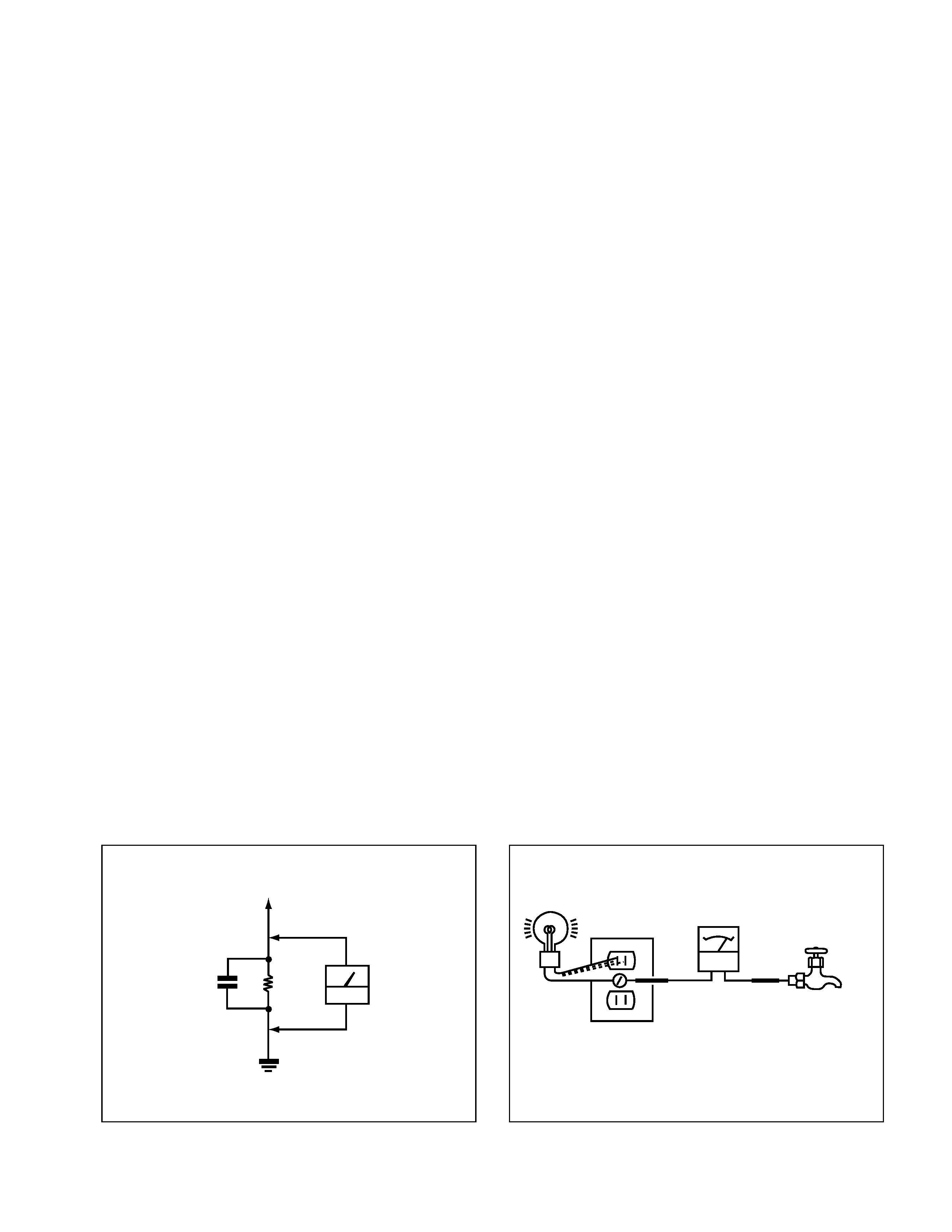
3. Measuring the voltage drop across a resistor by means of a
VOM or battery-operated AC voltmeter. The "limit" indica-
tion is 0.75V, so analog meters must have an accurate low-
voltage scale. The Simpson 250 and Sanwa SH-63Trd are
examples of a passive VOM that is suitable. NearIy all bat-
tery operated digital multimeters that have a 2V AC range
are suitable. (See Fig. A)
HOW TO FIND A GOOD EARTH GROUND
A cold-water pipe is guaranteed earth ground;the cover-plate re-
taining screw on most AC outlet boxes is also at earth ground. If
the retaining screw is to be used as your earth-ground, verify that it
is at ground by measuring the resistance between it and a cold-
water pipe with an ohmmeter. The reading should be zero ohms. If
a cold-water pipe is not accessible, connect a 60-l00 watts trouble
light (not a neon lamp) between the hot side of the receptacle and
the retaining screw. Try both slots, if necessary, to locate the hot
side of the line, the lamp should light at normal brilliance if the
screw is at ground potential. (See Fig. B)
To Exposed Metal
Parts on Set
AC
voltmeter
(0.75V)
1.5k
Earth Ground
Fig. A. Using an AC voltmeter to check AC leakage.
1.5
µ F
Fig. B. Checking for earth ground.
Trouble Light
AC Outlet Box
Ohmmeter
Cold-water Pipe
MC-Service
4
KP-43T75/48S75/
53N77/53S75/61S75
RM-Y906
SELF DIAGNOSIS FUNCTION
* : 000 the range of values for number of operations is 000-255. For 256 or higher there is
no count up and the number remains at 255.
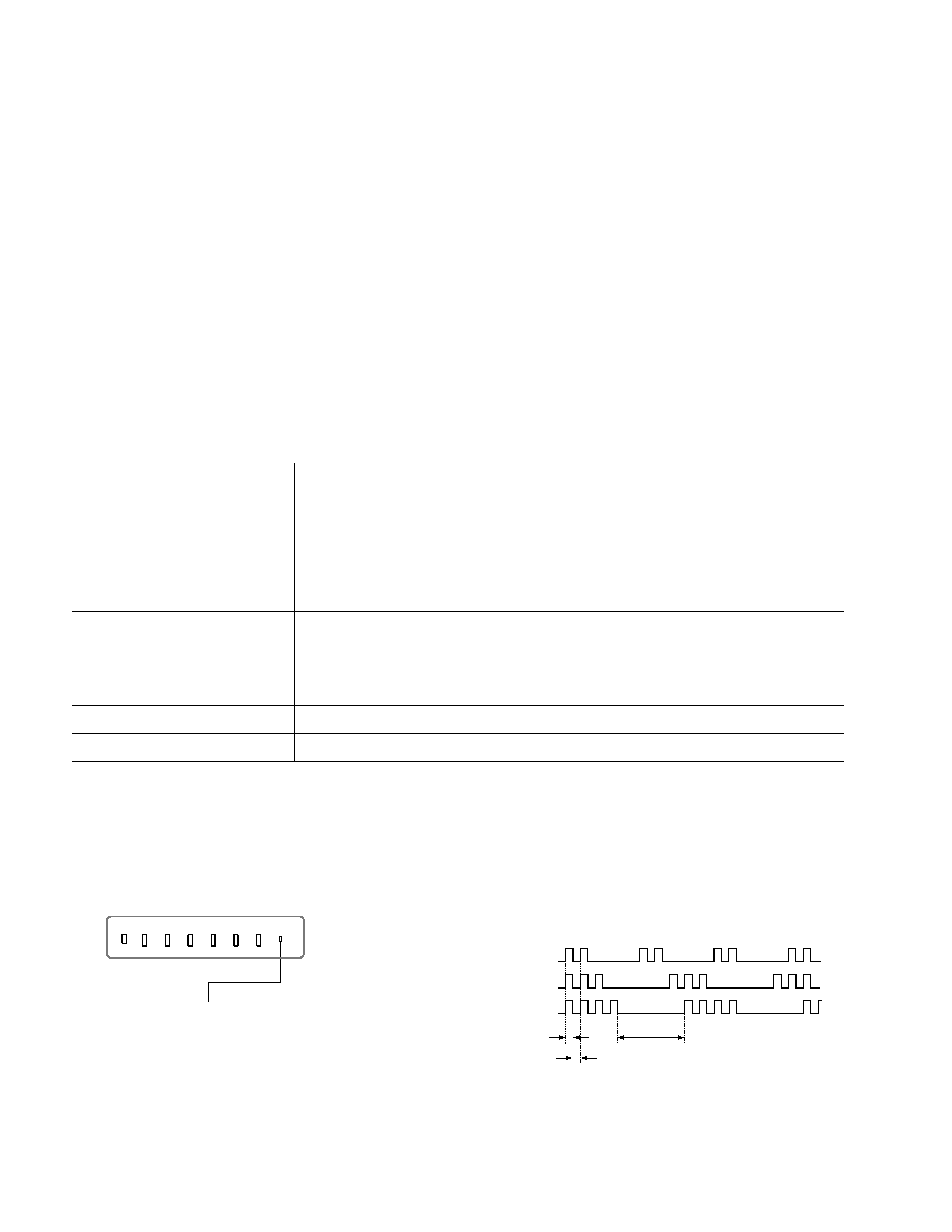
3.
Blinking count display of TIMER/STANDBY indicator
< FRONT PANEL >
TIMER/STANDBY indicator
Lamp OFF :
3.0 seconds
Lamp ON : 0.3 seconds
Lamp OFF : 0.3 seconds
Release of TIMER/STANDBY indicator blinking.
·
The TIMER/STANDBY indicator blinking display is released by turning OFF the power switch
on the TV main unit or removing the plug from the power.
* One blink is not used for self-diagnosis.
·EXAMPLE
<Diagnosis Items>
<Number of Blinks>
· +B overcurrent
2 times
· +B overvoltage
3 times
· Vertical deflection stop
4 times
TV/VIDEO
FLASH FOCUS
VOLUME
POWER TIMER/STAND BY
+
CHANNEL
+
1.
Summary of Self-Diagnosis Function
·
This device includes a self-diagnosis function.
·
In case of abnormalities, the TIMER/STANDBY indicator automatically blinks. It is possible to predict the abnormality location
by the number of blinks. The Instruction Manual describes blinking of the TIMER/STANDBY indicator.
·
If the symptom is not reproduced sometimes in case of a malfunction, there is recording of whether a malfunction was generated
or not. Operate the remote command to confirm the matter on the screen and to predict the location of the abnormality.
2.
Diagnosis Items and Prediction of Malfunction Location
·
When a malfunction occurs the TIMER/STANDBY indicator only blinks for one of the following diagnosis items. In case of two
or more malfunctions, the item which first occurred blinks. If the malfunctions occurred simultaneously, the item with the lower
blink count blinks first.
·
The screen display displays the results regarding all the diagnosis items listed below. The display " 0 " means that no malfunc-
tions occurred.
m
e
t
i
s
i
s
o
n
g
a
i
D
Y
B
D
N
A
T
S
/
R
E
M
I
T
r
e
t
a
c
i
d
n
I
s
k
n
i
l
b
f
o
r
e
b
m
u
N
n
o
i
t
c
n
u
f
l
a
m
d
e
s
o
p
p
u
Sn
o
i
t
i
d
n
o
C
s
i
s
o
n
g
a
i
d
-
f
l
e
S
,
y
a
l
p
s
i
d
n
e
e
r
c
s
s
t
l
u
s
e
R
:
m
e
t
i
s
i
s
o
n
g
a
i
D
N
O
t
o
n
r
e
w
o
P
·0
]
m
e
t
s
y
S
y
l
p
p
u
S
r
e
w
o
P
y
b
d
n
a
t
S
[
.
n
e
p
o
1
0
6
F
.
n
e
p
o
7
0
6
R
t
i
u
c
r
i
c
t
r
o
h
s
1
0
6
Q
]
m
e
t
s
y
S
y
l
p
p
u
S
r
e
w
o
P
n
i
a
M
[
.
n
e
k
o
r
b
e
r
a
2
1
6
R
d
n
a
1
0
6
C
I
t
i
u
c
r
i
c
-
t
r
o
h
s
1
0
6
R
D
V
.
r
e
w
o
p
e
h
t
n
o
n
r
u
t
t
o
n
n
a
C
.
k
n
il
b
t
'
n
s
e
o
d
D
E
L
n
o
i
t
c
e
t
e
d
P
C
O
B
+s
e
m
i
t
2.
t
i
u
c
r
i
c
h
c
a
e
n
i
m
e
t
s
y
s
y
l
p
p
u
s
r
e
w
o
p
f
o
t
i
u
c
r
i
c
t
r
o
h
S
e
d
o
m
y
b
d
n
a
t
s
e
h
t
o
t
s
e
o
G
e
n
il
B
+
f
o
t
i
u
c
r
i
c
t
r
o
h
S
0
0
0
P
C
O
B
+
:
2
n
o
i
t
c
e
t
e
d
P
V
O
B
+s
e
m
i
t
3
.
n
e
p
o
8
7
n
i
p
3
0
6
T
.
n
e
p
o
2
7
6
R
e
d
o
m
y
b
d
n
a
t
s
e
h
t
o
t
s
e
o
G
t
i
u
c
r
i
c
y
l
p
p
u
s
r
e
w
o
p
f
o
n
o
i
t
c
n
u
f
l
a
M
0
0
0
P
V
O
B
+
:
3
p
o
t
s
n
o
i
t
c
e
l
f
e
d
l
a
c
i
t
r
e
Vs
e
m
i
t
4
.
n
e
k
o
r
b
s
i
)
t
u
o
V
(
9
0
5
1
C
I
.
n
e
k
o
r
b
s
i
)
r
e
f
f
u
B
e
s
l
u
P
V
(
5
0
5
1
Q
o
e
d
i
v
n
e
h
t
d
n
a
A
,
y
ll
a
t
n
o
z
i
r
o
h
e
n
il
e
n
o
o
t
s
e
o
g
r
e
t
s
a
R
.
d
e
t
u
m
s
i
l
a
n
g
i
s
0
0
0
p
o
t
S
V
:
4
n
o
i
t
c
e
t
e
d
y
t
il
a
m
r
o
n
b
a
t
u
o
o
e
d
i
Vs
e
m
i
t
5
d
r
a
o
b
C
n
i
s
r
e
h
t
o
d
n
a
1
6
7
,
2
3
7
,
5
0
7
Q
,
t
u
o
o
e
d
i
V
.
t
i
u
c
r
i
c
)
d
r
a
o
b
A
(
0
2
2
,
9
1
2
,
8
1
2
Q
,
s
d
n
o
c
e
s
0
3
.
x
o
r
p
p
a
s
k
n
il
b
D
E
L
Y
B
D
N
A
T
S
/
R
E
M
I
T
.
s
i
s
o
n
g
a
i
d
f
l
e
s
e
h
t
r
o
f
s
k
n
il
b
n
e
h
t
d
n
a
0
0
0
B
K
A
:
5
p
o
t
s
n
o
i
t
c
e
l
f
e
d
l
a
t
n
o
z
i
r
o
Hs
e
m
i
t
6
.
n
e
p
o
6
1
5
,
5
1
5
C
.
n
e
k
o
r
b
s
i
)
e
l
g
n
u
J
C
Y
(
6
0
2
C
I
.
r
a
e
p
p
a
t
'
n
s
e
o
d
r
e
t
s
a
R0
0
0
p
o
t
S
H
:
6
n
o
i
t
c
e
t
e
d
y
t
il
a
m
r
o
n
b
a
o
i
d
u
As
e
m
i
t
8
.
n
e
k
o
r
b
s
i
)
.
p
m
a
o
i
d
u
A
(
6
0
4
C
I
.
n
e
p
o
2
0
4
,
1
0
4
S
P
.
t
u
o
t
o
n
s
i
d
n
u
o
s
e
h
T
e
d
o
m
y
b
d
n
a
t
s
e
h
t
o
t
s
e
o
G
0
0
0
o
i
d
u
A
:
8