CHASSIS
MODEL
MODEL
SERVICE MANUAL
MICROFILM
CHASSIS No.
CHASSIS No.
COMMANDER
DEST.
COMMANDER DEST.
LCD PROJECTION DATA MONITOR
37
* Please file according to model size...
50
LJ-2T
KL-W9000
KL-W9000
KL-W7000
KL-W7000
KL-W7000
KL-W9000
RM-Y980
SCC-N56B-A
SCC-N56B-A
RM-Y980
RM-Y980
US
Canadian
RM-Y980
RM-Y980
US
Canadian
SCC-N56A-A
SCC-N56A-A

KL-W7000/W9000
RM-Y980
2
Specifications
Acceptable signal NTSC video signal, RGB signal
(For details, see page 9.)
Projection system 3 LCD panels, 1 lens projection
system
LCD panel
1.35-inch TFT LCD panel
Approx. 1.54 million dots
(512,880 pixels)
1068.5
× 480 dots × 3 panels
Lamp
XL-100U: HID lamp, 100 W
Lens
Large diameter hybrid lens F2.4
Screen size (measured diagonally)
KL-W7000: 37 inches (942 mm)
KL-W9000: 50 inches (1,272 mm)
Viewable image size (for RGB input)
KL-W7000: Approx. 36.3 inches
(921 mm) (diagonally)
Approx. 803
× 452 mm (w/h)
KL-W9000: Approx. 49.1 inches
(1247 mm) (diagonally)
Approx. 1087
× 611 mm (w/h)
Deflection frequency
Horizontal: 31.548 kHz
Vertical: 5085 Hz
Inputs/outputs
VIDEO 1, 2 and 3 IN
S VIDEO (VIDEO 1, 3 IN only)
(4-pin mini-DIN):
Y: 1 Vp-p, 75 ohms
unbalanced, sync negative
C: 0.286 Vp-p (burst signal), 75
ohms
VIDEO (phono jacks):
1 Vp-p, 75 ohms unbalanced,
sync negative
AUDIO (phono jacks):
2 channels, 500 mVrms
Impedance: more than 47
kohms
VIDEO OUT
S VIDEO (4-pin mini-DIN):
Y: 1 Vp-p, 75 ohms
unbalanced, sync negative
C: 0.286 Vp-p (burst signal), 75
ohms
VIDEO (phono jacks):
1 Vp-p, 75 ohms unbalanced,
sync negative
AUDIO (phono jacks):
2 channels, 500 mVrms
Impedance: less than 5 kohms
RGB 1, 2 IN
VIDEO (D-sub 15-pin, female):
R, G, B: 0.7 Vp-p, positive, 75
ohms terminated
Sync on Green: 0.286 Vp-p
SYNC/HD: Composite sync:
TTL, high impedance,
sync positive/negative
Horizontal sync: TTL, high
impedance, sync positive/
negative
VD: Vertical sync: TTL, high
impedance, sync positive/
negative
AUDIO (RGB 1 IN) (phono
jacks)
2 channels, 500 mVrms
Impedance: more than 47
kohms
AUDIO (RGB 2 IN) (stereo
minijack)
500 mVrms
Impedance: more than 47
kohms
Power requirement
100 to 120 V AC, 50/60 Hz
Power consumption
190 W (MAX)
Standby mode: 2 W
Dimensions
KL-W7000: 920 x 825 x 390 mm
(361/4
× 321/2 × 153/8 inches)
(w/h/d)
KL-W9000: 1,228
× 1,055 × 565
mm (483/8
× 415/8 × 221/4
inches) (w/h/d)
Mass
KL-W7000: Approx. 30 kg
(68 lbs 2 oz)
KL-W9000: Approx. 43 kg
(106 lbs 8 oz)
Supplied accessories
Remote control RM-Y980 (1)
Size AA (R6) batteries (2)
AC power cord (1)
RGB signal cable (D-sub 15-pin
~ D-sub 15-pin) (1)
HD15-HD15 (male, without the
No. 9 pin) adaptor (1)
Macintosh adaptor (1)
Windows 95 Monitor
Information Disk (1)
Brackets (2)
Screws for brackets (2)
Buckle (1)
Hexagon head wrench (1)
Dust remover (1)
Optional accessories
Lamp unit XL-100U
Design and specifications are subject to change
without notice.
3
KL-W7000/W9000
RM-Y980
SAFETY CHECK-OUT
(US Model only)
LEAKAGE TEST
The AC leakage from any exposed metal part to earth ground
and from all exposed metal parts to any exposed metal part having a
return to chassis, must not exceed 0.5 mA (500 microampers).
Leakage current can be measured by any one of three methods.
1. A commercial leakage tester, such as the Simpson 229 or
RCA WT-540A. Follow the manufacturers' instructions to
use these instruments.
2. A battery-operated AC milliammeter. The Data Precision 245
digital multimeter is suitable for this job.
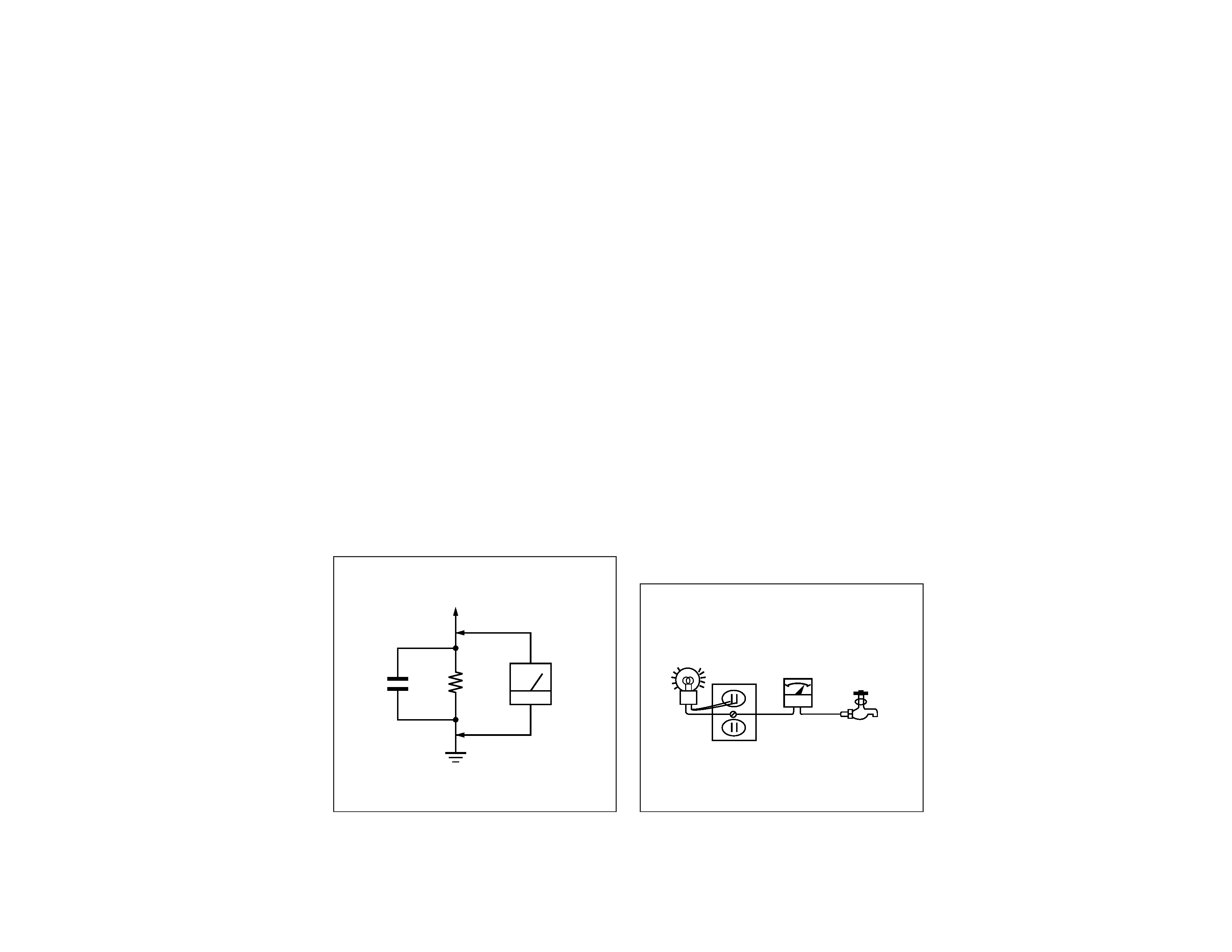
3. Measuring the voltage drop across a resistor by means of a
VOM or battery-operated AC voltmeter. The "limit" indica-
tion is 0.75 V, so analog meters must have an accurate low-
voltage scale. The Simpson 250 and Sanwa SH-63Trd are ex-
amples of a passive VOMs that are suitable. Nearly all battery
operated digital multimeters that have a 2 V AC range are suit-
able. (See Fig. A)
HOW TO FIND A GOOD EARTH GROUND
A cold-water pipe is guaranteed earth ground; the cover-plate
retaining screw on most AC outlet boxes is also at earth ground. If
the retaining screw is to be used as your earth-ground, verify that it
is at ground by measuring the resistance between it and a cold-
water pipe with an ohmmeter. The reading should be zero ohms. If
a cold-water pipe is not accessible, connect a 60 100 watts
trouble light (not a neon lamp) between the hot side of the recep-
tacle and the retaining screw. Try both slots, if necessary, to locate
the hot side of the line, the lamp should light at normal brilliance if
the screw is at ground potential. (See Fig. B)
After correcting the original service problem, perform the fol-
lowing safety checks before releasing the set to the customer:
1. Check the area of your repair for unsoldered or poorly-sol-
dered connections. Check the entire board surface for solder
splashes and bridges.
2. Check the interboard wiring to ensure that no wires are
"pinched" or contact high-wattage resistors.
3. Check that all control knobs, shields, covers, ground straps,
and mounting hardware have been replaced. Be absolutely
certain that you have replaced all the insulators.
4. Look for unauthorized replacement parts, particularly transis-
tors, that were installed during a previous repair. Point them
out to the customer and recommend their replacement.
5. Look for parts which, though functioning, show obvious signs
of deterioration. Point them out to the customer and recom-
mend their replacement.
6. Check the line cords for cracks and abrasion. Recommend the
replacement of any such line cord to the customer.
7. Check the condition of the monopole antenna (if any).
Make sure the end is not broken off, and has the plastic cap on
it. Point out the danger of impalement on a broken antenna to
the customer, and recommend the antenna's replacement.
8. Check the B+ and HV to see if they are specified values. Make
sure your instruments are accurate; be suspicious of your HV
meter if sets always have low HV.
9. Check the antenna terminals, metal trim, "metallized" knobs,
screws, and all other exposed metal parts for AC Leakage.
Check leakage as described below.
1.5 k
0.15 µF
AC
Voltmeter
(0.75 V)
To Exposed Metal
Parts on Set
Earth Ground
Fig. A. Using an AC voltmeter to check AC leakage.
Trouble Light
AC Outlet Box Ohmmeter
Cold-water Pipe
Fig. B. Checking for earth ground.

4
KL-W7000/W9000
RM-Y980
TABLE OF CONTENTS
Section
Title
Page
Section
Title
Page
1. GENERAL ..................................................................
5
2. DISASSEMBLY
2-1.
Rear Cover Removal ........................................... 18
2-2.
Chassis Assy Removal ........................................ 18
2-3.
Service Position ................................................... 18
2-4.
U Board Removal ................................................ 18
2-5
Power Block and K Board Removal ................... 19
2-6.
Filter Removal ..................................................... 19
2-7.
Lamp Removal .................................................... 20
2-8.
HA and HB Boards Removal .............................. 20
2-9-1. Screen Frame Removal [W7000] ........................ 20
2-9-2. Screen Frame Removal [W9000] ........................ 20
2-10-1.C Board Removal ................................................ 21
2-10-2.Extension Cable (C Board) .................................. 21
2-11.
Optical Unit Removal .......................................... 21
3. CIRCUIT ADJUSTMENTS ................................ 22
4. DIAGRAMS
4-1.
Block Diagrams ................................................... 39
4-2.
Circuit Boards Location ....................................... 53
4-3.
Schematic Diagrams and Printed
Wiring Boards ................................................. 54
(1)
Schematic Diagrams of HA,HB, K,
TA and TB Boards ........................................... 55
(2)
Schematic Diagram of A (1/3) Board ................... 63
(3)
Schematic Diagram of A (2/3) Board ................... 67
(4)
Schematic Diagram of A (3/3) Board ................... 71
(5)
Schematic Diagram of BB Board .......................... 75
(6)
Schematic Diagram of U Board ............................ 83
(7)
Schematic Diagram of C (1/2) Board .................... 87
(8)
Schematic Diagram of C (2/2) Board .................... 91
(9)
Schematic Diagrams of G and GA Boards ............ 95
4-4.
Semiconductors ................................................... 99
5. EXPLODED VIEWS
5-1.
Chassis [W7000] ................................................. 101
5-2.
Front Cover [W7000] .......................................... 102
5-3.
Screen Mirror Block and Optics Unit [W7000] .. 103
5-4.
Chassis [W9000] ................................................. 104
5-5.
Front Cover [W9000] .......................................... 105
5-6.
Screen Mirror Block and Optics Unit [W9000] .. 106
6. ELECTRICAL PARTS LIST ............................ 107
SAFETY-RELATED COMPONENT WARNING!!
COMPONENTS IDENTIFIED BY SHADING AND MARK
¡
ON THE SCHEMATIC DIAGRAMS, EXPLODED VIEWS
AND IN THE PARTS LIST ARE CRITICAL TO SAFE
OPERATION. REPLACE THESE COMPONENTS WITH
SONY PARTS WHOSE PART NUMBERS APPEAR AS
SHOWN IN THIS MANUAL OR IN SUPPLEMENTS
PUBLISHED BY SONY.
ATTENTION AUX COMPOSANTS RELATIFS À LA
SÉCURITÉ!!
LES COMPOSANTS IDENTIFIÉS PAR UNE TRAME ET
UNE MARQUE
¡ SONT CRITIQUES POUR LA
SÉCURITÉ. NE LES REMPLACER QUE PAR UNE PIÈCE
PORTANT LE NUMÉRO SPECIFIÉ. LES RÉGLAGES DE
CIRCUIT DONT L'IMPORTANCE EST CRITIQUE POUR
LA
SÉCURITÉ
DU
FONCTIONNEMENT
SONT
IDENTIFIÉS DANS LE PRÉSENT MANUEL. SUIVRE CES
PROCÉDURES LORS DE CHAQUE REMPLACEMENT DE
COMPOSANTS CRITIQUES, OU LORSQU'UN MAUVAIS
FONCTIONNE-MENT EST SUSPECTÉ.
5
SECTION 1
GENERAL
The operating instructions mentioned here are partial abstracts
from the Operating Instruction Manual. The page numbers of
the Operating Instruction Manual remain as in the manual.
4-EN
Welcome!
Precautions
This projection monitor operates on extremely high
voltage. To prevent fire or electric shock, please follow
the precautions below.
On safety
· Operate the monitor only on 100 V to 120 V AC.
· One blade of the plug is wider than the other for
safety purposes and will fit into the power outlet
only one way. If you are unable to insert the plug
fully into the outlet, contact your dealer.
· Should any liquid or solid object fall into the
cabinet, unplug the monitor and have it checked by
qualified personnel before operating it further.
· Unplug the monitor from the wall outlet if you are
not going to use it for several days or more. To
disconnect the cord, pull it out by the plug. Never
pull the cord itself.
· The fans inside the monitor continue working for a
while even after the monitor has been turned off.
Do not unplug the monitor from the AC outlet
while the fans are working.
On installation
· To prevent internal heat build-up, do not block the
ventilation openings.
· Do not install the monitor in a hot or humid place,
or in a place subject to excessive dust or mechanical
vibration.
On screen
The screen surface is easily scratched. Do not rub,
touch or tap it with sharp or abrasive objects.
Be especially careful when transporting the monitor.
On LCD panel
· Do not expose the screen to direct sunlight. It may
damage the LCD panel.
· When the monitor is used in a cold place, the image
may look lengthened. This is not a malfunction. The
image will become normal when the temperature
rises.
· When the same static picture has been displayed
continuously, an afterimage impression of that
picture may remain on the screen. This will
disappear after a certain time.
· If you turn on the monitor immediately after power
has been restored at an interruption, an LCD burn
may occur. This is not a malfunction. The image will
become normal after a certain time.
On blanking around the pciture
The monitor displays black masks between the picture
and the screen vessel because the monitor under-scans
to obtain the necessary space on the screen to display
the picture. This is called blanking. Note that the black
masks on each vessel are not uniform.
The blanking on the video picture will be wider to
optimize picture.
On moisture condensation
If the projection monitor is transported directly from a
cold to a warm location, or if the room temperature
has changed suddenly, the picture may be blurred or
show poor color. This is because moisture has
condensed on the lenses inside. If this happens, let the
moisture evaporate before using the monitor.
On cleaning
· Clean the cabinet of the monitor with a dry soft
cloth. Stubborn stains may be removed with a cloth
slightly dampened with solution of mild soap and
water, then wipe it with a dry soft cloth.
Do not use any type of solvent such as alcohol,
benzine, thinner or insecticide. Such solvent may
damage the finish of the monitor or erase the
indications on the panel.
· Wipe the screen with a dust remover (supplied)
occasionally, as the screen easily catches dust. The
dust remover is washable. Wash it with warm water
or mild detergent solution.
· Stubborn stains on the screen may be removed with
a soft cloth slightly dampened with solution of mild
soap and water.
· If the picture becomes dark after using the monitor
for a long period of time, it may be necessary to
clean the inside of the monitor. Consult qualified
service personnel.
Screen vessel
Picture
Blanking
Getting Started
5-EN
EN
p
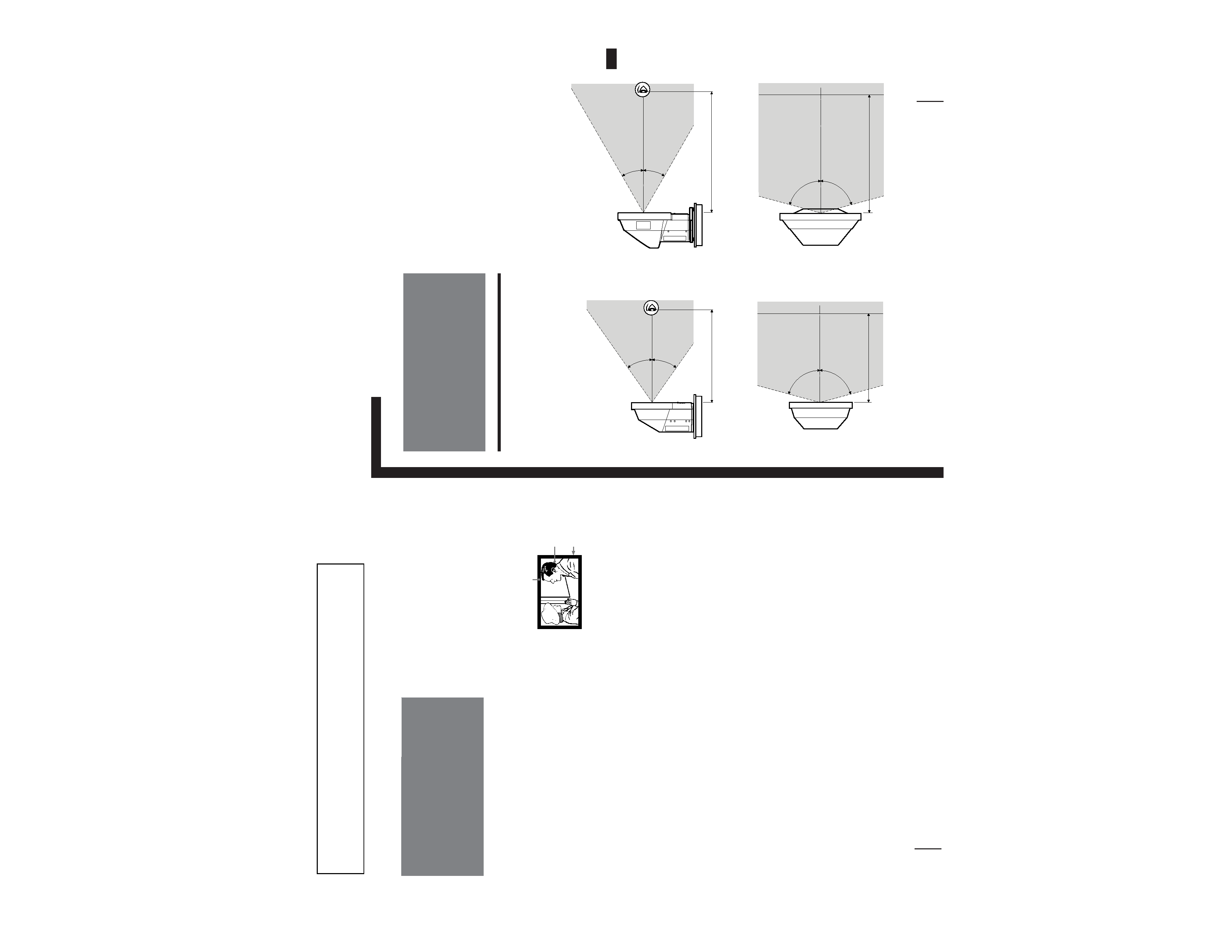
for KL-W9000
Vertical viewing area (side view)
Horizontal viewing area (top view)
Getting Started
Step 1: Installing
the projection
monitor
Optimum viewing area
For the best picture quality, install the monitor within
the areas shown below.
p
for KL-W7000
Vertical viewing area (side view)
Horizontal viewing area (top view)
30
°
30
°
2 m
75
°
75
°
2 m
35
°
35
°
75
°
75
°
1.5 m
1.5 m