SERVICE MANUAL
SPECIFICATIONS
WAX CHASSIS
KLV-S19A10/S23A10
FLAT PANEL COLOR TV
US Model
Canadian Model
KLV-S19A10
KLV-S23A10
Television system:
American TV standard
Channel coverage:
VHF: 2-13/UHF: 14-69/CATV: 1-125
Antenna:
75-ohm external terminal for VHF/UHF
Screen size (measured diagonally):
KLV-S19A10: 19 inches
KLV-S23A10: 23 inches
Panel System:
LCD (Liquid Crystal Display) Panel
Display resolution (horizontal
× vertical):
KLV-S19A10: 1,280 dots
× 768 lines
KLV-S23A10: 1,366 dots
× 768 lines
VIDEO IN 1/2/3:
S VIDEO (4-pin mini DIN):
Y: 1.0 Vp-p, 75 ohms unbalanced, sync
negative
C: 0.286 Vp-p (Burst signal), 75 ohms
VIDEO:
1 Vp-p, 75 ohms unbalanced, sync negative
AUDIO:
500 mVrms (100% modulation)
Impedance: 47 kilohms
HD/DVD IN 4:
YPBPR (Component Video):
Y: 1.0 Vp-p, 75 ohms unbalanced, sync
negative
PB:0.7 Vp-p, 75 ohms
PR:0.7 Vp-p, 75 ohms
Signal format: 480i, 480p, 720p, 1080i
AUDIO:
500 mVrms (100% modulation)
500 mVrms (100% modulation)
500 mVrms (100% modulation)
Impedance: 47 kilohms
Impedance: 47 kilohms
HDMI IN 5:
HDMI:
Video:480i, 480p, 720p, 1080i
Audio:Two channel linear PCM 32, 44.1
and 48 kHz, 16, 20 and 24 bits
AUDIO:
AUDIO OUT:
More than 1 Vrms at the maximum volume setting (Variable)
More than 500 mVrms (Fixed)
PC IN 6:
D-sub 15-pin, analog RGB, 0.7 Vp-p, 75 ohms, positive
PC AUDIO INPUT:
Stereo mini jack, 0.5 Vrms, 1 kilohm
Headphones:
Stereo mini jack
Impedance:
16 ohms
KLV-S19A10/S23A10 (UC)
2
Speaker:
Full range:
4
× 10 cm (15 7/8 × 39 3/8 inches) (2)
Speaker output:
5 W + 5 W
Power requirement:
KLV-S23A10: 120-240 V AC, 50/60 Hz
KLV-S19A10: 18 V DC, with AC power adaptor
AC power adaptor for KLV-S19A10:
Model name:
AC-FD008
Rating:
Input AC 100 V-240 V
50/60 Hz, 128 W
Output DC 18 V 6.11 A
Power consumption:
In use:
KLV-S19A10: 95 W
KLV-S19A10: Less than 1.3 W
KLV-S23A10: Less than 1 W
KLV-S23A10: 110 W
In standby:
Dimensions (W/H/D):
KLV-S19A10: (with stand) 468
× 402 × 218 mm
(18
1/2
× 15 7/8 × 8 5/8 inches)
(18
1/2
× 14 3/8 × 3 3/8 inches)
(without stand) 468
× 364 × 84 mm
KLV-S23A10: (with stand) 566
× 448 × 218 mm
(22
3/8
× 17 3/4 × 8 5/8 inches)
(22
3/8
× 16 1/4 × 3 5/8 inches)
(without stand) 566
× 411 × 89 mm
Mass:
KLV-S19A10: (with stand) 9.9 kg (21 lb. 14 oz.)
(without stand) 6.3 kg (13 lb. 15 oz.)
KLV-S23A10: (with stand) 12.3 kg (27 lb. 2 oz.)
(without stand) 8.7 kg (19 lb. 3 oz.)
Supplied accessories:
Remote control RM-YA001 (1)
Size AA batteries (2)
75-ohm coaxial cable (1)
AC power cord (1)
AC power adaptor (1) (KLV-S19A10 only)
HD15-HD15 cable (1)
Support belt (1), securing screw (1) and wood screw (1)
Operating Instructions (1)
Quick Setup Guide (1)
Leaflet (Installing the Wall-Mount Bracket to the TV) (1)
Warranty Card (1)
Optional accessories:
Headphones plug adaptor
Connecting cables
Wall-Mount Bracket SU-WL11 (KLV-S19A10)
SU-LW1 (KLV-S23A10)
Design and specifications are subject to change
without notice.
Optional accessories' availability may
depend on its stock.
KLV-S19A10/S23A10 (UC)
3
WARNINGS AND CAUTIONS
KLV-S19A10/S23A10 (UC)
4
SAFETY CHECK-OUT
After correcting the original service problem, perform the
following safety checks before releasing the set to the customer:
1. Check the area of your repair for unsoldered or poorly-sol-
dered connections. Check the entire board surface for solder
splashes and bridges.
2. Check the interboard wiring to ensure that no wires are
"pinched" or contact high-wattage resistors.
3. Check that all control knobs, shields, covers, ground straps,
and mounting hardware have been replaced. Be absolutely cer-
tain that you have replaced all the insulators.
4. Look for unauthorized replacement parts, particularly transis-
tors, that were installed during a previous repair. Point them
out to the customer and recommend their replacement.
5. Look for parts which, though functioning, show obvious signs
of deterioration. Point them out to the customer and recom-
mend their replacement.
6. Check the line cords for cracks and abrasion. Recommend the
replacement of any such line cord to the customer.
7. Check the antenna terminals, metal trim, "metallized" knobs,
screws, and all other exposed metal parts for AC Leakage.
Check leakage as described right.
LEAKAGE TEST
The AC leakage from any exposed metal part to earth ground and
from all exposed metal parts to any exposed metal part having a
return to chassis, must not exceed 0.5 mA (500 microamperes).
Leakage current can be measured by any one of three methods.
1. A commercial leakage tester, such as the Simpson 229 or RCA
WT-540A. Follow the manufacturers' instructions to use these
instruments.
2. A battery-operated AC milliammeter. The Data Precision 245
digital multimeter is suitable for this job.
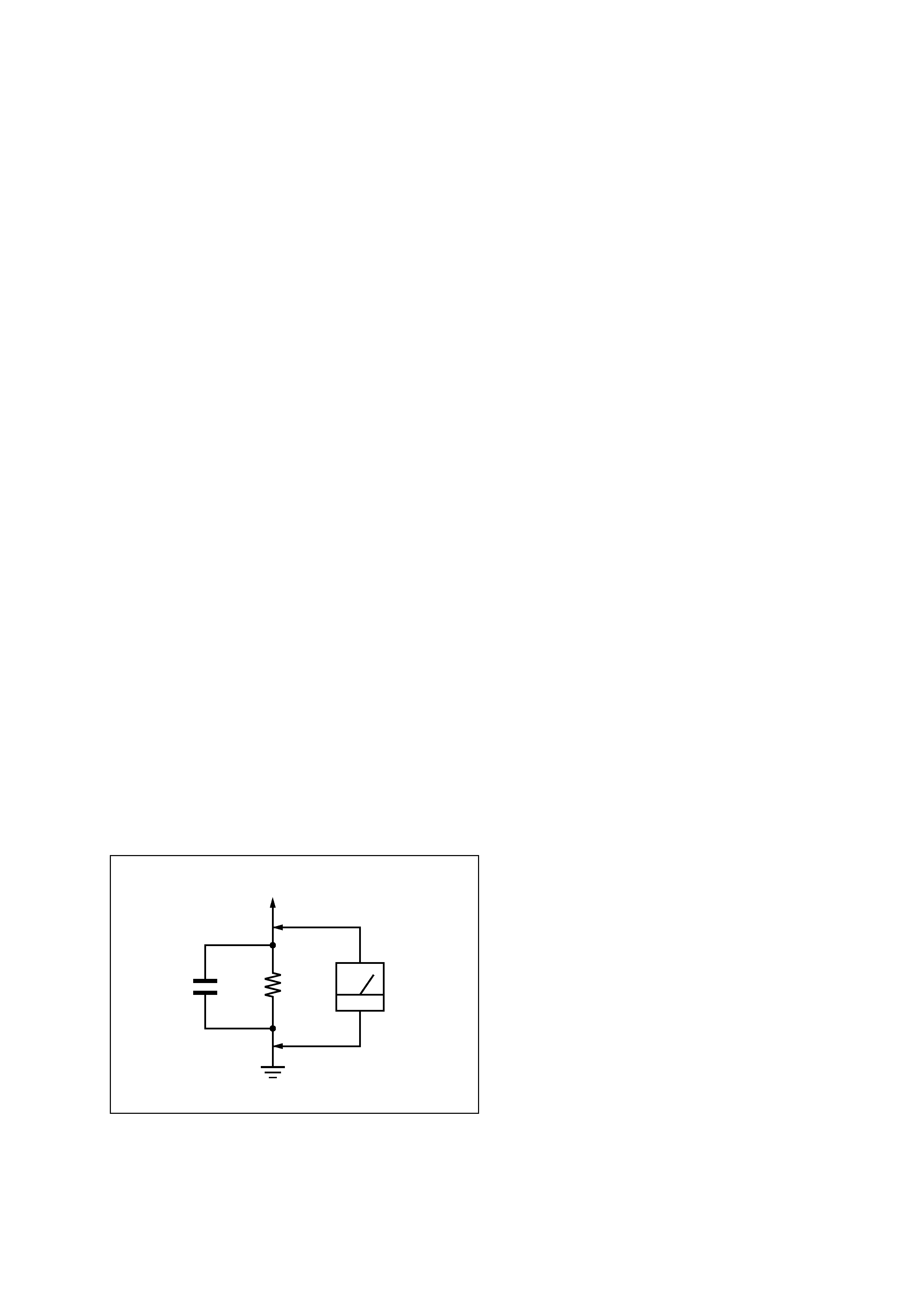
3. Measuring the voltage drop across a resistor by means of a
VOM or battery-operated AC voltmeter. The "limit" indica-
tion is 0.75 V, so analog meters must have an accurate low-
voltage scale. The Simpson 250 and Sanwa SH-63Trd are ex-
amples of a passive VOMs that are suitable. Nearly all battery
operated digital multimeters that have a 2 V AC range are suit-
able. (See Fig. A)
Fig. A. Using an AC voltmeter to check AC leakage.
1.5 k
0.15 µF
AC
Voltmeter
(0.75 V)
To Exposed Metal
Parts on Set
Earth Ground
WARNING!!
SAFETY-RELATED COMPONENT WARNING!!
COMPONENTS IDENTIFIED BY SHADING AND MARK
!
ON THE SCHEMATIC DIAGRAMS, EXPLODED VIEWS
AND IN THE PARTS LIST ARE CRITICAL FOR SAFE
OPERATION. REPLACE THESE COMPONENTS WITH
SONY PARTS WHOSE PART NUMBERS APPEAR AS
SHOWN IN THIS MANUAL OR IN SUPPLEMENTS PUB-
LISHED BY SONY. CIRCUIT ADJUSTMENTS THAT ARE
CRITICAL FOR SAFE OPERATION ARE IDENTIFIED IN
THIS MANUAL. FOLLOW THESE PROCEDURES WHEN-
EVER CRITICAL COMPONENTS ARE REPLACED OR
IMPROPER OPERATION IS SUSPECTED.
AVERTISSEMENT!!
ATTENTION AUX COMPOSANTS RELATIFS À LA
SÉCURITÉ!!
LES COMPOSANTS IDENTIFIÉS PAR UNE TRAME ET
UNE MARQUE ! SONT CRITIQUES POUR LA
SÉCURITÉ. NE LES REMPLACER QUE PAR UNE
PIÈCE PORTANT LE NUMÉRO SPECIFIÉ. LES
RÉGLAGES DE CIRCUIT DONT L'IMPORTANCE EST
CRITIQUE POUR LA SÉCURITÉ DU
FONCTIONNEMENT SONT IDENTIFIÉS DANS LE
PRÉSENT MANUEL. SUIVRE CES PROCÉDURES
LORS DE CHAQUE REMPLACEMENT DE
COMPOSANTS CRITIQUES, OU LORSQU'UN MAUVAIS
FONCTIONNEMENT EST SUSPECTÉ.

KLV-S19A10/S23A10 (UC)
5
TABLE OF CONTENTS
1. SELF-DIAGNOSIS FUNCTION .................... 1-1
1-1.
CONTROL BUTTONS ...................................... 1-1
1-2.
LED BLINKING PATTERNS AND
MONITORING ITEMS ..................................... 1-2
2. DISASSEMBLY ............................................ 2-1
2-1.
KLV-S19A10 ..................................................... 2-1
2-1-1. STAND ASSY REMOVAL .......................... 2-1
2-1-2. REAR CABINET ASSY REMOVAL .......... 2-1
2-1-3. H1 BOARD REMOVAL ............................... 2-2
2-1-4. VESA BRACKET, SIDE BRACKET ASSY
AND S1 SHEILD TOP REMOVAL ............. 2-2
2-1-5. A1U BOARD AND SIDE JACK HOLDER
ASSY REMOVAL ......................................... 2-3
2-1-6. P BOARD REMOVAL .................................. 2-3
2-1-7. TU BOARD REMOVAL .............................. 2-4
2-1-8. B BOARD REMOVAL ................................. 2-4
2-1-9. H3 BOARD AND SPEAKER REMOVAL
........................................................................ 2-5
2-1-10. LCD PANEL REMOVAL ............................. 2-6
2-2.
KLV-S23A10 ..................................................... 2-7
2-2-1. STAND ASSY REMOVAL .......................... 2-7
2-2-2. REAR CABINET REMOVAL ...................... 2-7
2-2-3. H1 BOARD REMOVAL ............................... 2-8
2-2-4. PLATE BRIDGE ASSY AND ARM (L), (R)
REMOVAL .................................................... 2-8
2-2-5. S1 SHEILD TOP, SIDE BRACKET ASSY
AND BOTTOM BRACKET REMOVAL .... 2-9
2-2-6. G1 AND H2 BOARDS REMOVAL ............. 2-9
2-2-7. A2U BOARD REMOVAL ............................ 2-10
2-2-8. P AND TU BOARDS REMOVAL ............... 2-10
2-2-9. B BOARD REMOVAL ................................. 2-11
2-2-10. H3 BOARD AND SPEAKER REMOVAL
........................................................................ 2-11
2-2-11. LCD PANEL REMOVAL ............................. 2-12
3. SERVICE MODE ........................................... 3-1
3-1.
DISPLAYING SERVICE MENU ..................... 3-1
3-2.
ADJUSTMENT USING THE SERVICE MENU
............................................................................ 3-1
4. DIAGRAMS ................................................... 4-1
4-1.
BLOCK DIAGRAMS ........................................ 4-1
(1)
A1U (1/2) and TU boards
(KLV-S19A10 Only) ..................................... 4-1
(2)
A1U (2/2) board (KLV-S19A10 Only) ......... 4-2
(3)
A2U (1/2), TU and H2 boards
(KLV-S23A10 Only) ..................................... 4-3
(4)
A2U (2/2) board (KLV-S23A10 Only) ......... 4-4
(5)
B, H1and H3 boards ....................................... 4-5
(6)
G1 board (KLV-S23A10 Only) ..................... 4-6
(7)
P board ........................................................... 4-7
4-2.
FRAME DIAGRAMS ........................................ 4-8
4-2-1. KLV-S19A10 ................................................. 4-8
4-2-2. KLV-S23A10 ................................................. 4-9
4-3.
CIRCUIT BOARDS LOCATION ..................... 4-10
4-3-1. KLV-S19A10 ................................................. 4-10
4-3-2. KLV-S23A10 ................................................. 4-10
4-4.
SCHEMATIC DIAGRAMS AND PRINTED
WIRING BOARDS ........................................... 4-10
(1)
Schematic Diagrams of A1U Board
(KLV-S19A10 Only) ..................................... 4-11
(2)
Schematic Diagrams of A2U Board
(KLV-S23A10 Only) ..................................... 4-17
(3)
Schematic Diagram of G1 Board
(KLV-S23A10 Only) ..................................... 4-23
(4)
Schematic Diagram of H1 and H2 Boards
(H2:KLV-S23A10 Only) ............................... 4-25
(5)
Schematic Diagram of H3 Board .................. 4-26
(6)
Schematic Diagram of TU Board .................. 4-27
(7)
Schematic Diagram of P Board ..................... 4-28
4-5.
SEMICONDUCTORS ....................................... 4-30
5. EXPLODED VIEWS ...................................... 5-1
5-1.
KLV-S19A10 ..................................................... 5-2
5-1-1. REAR CABINET ASSY AND STAND ASSY
........................................................................ 5-2
5-1-2. CHASSIS-1 ...................................................... 5-3
5-1-3. CHASSIS-2 ...................................................... 5-4
5-1-4. CHASSIS-3 ...................................................... 5-5
5-1-5. LCD PANEL .................................................... 5-6
5-1-6. PACKING MATERIALS ................................ 5-7
5-2.
KLV-S23A10 ..................................................... 5-8
5-2-1. REAR CABINET ASSY AND STAND ASSY
........................................................................ 5-8
5-2-2. CHASSIS-1 ...................................................... 5-9
5-2-3. CHASSIS-2 ...................................................... 5-10
5-2-4. CHASSIS-3 ...................................................... 5-11
5-2-5. CHASSIS-4 ...................................................... 5-12
5-2-6. LCD PANEL .................................................... 5-13
5-2-7. PACKING MATERIALS ................................ 5-14
6.
ELECTRICAL PARTS LIST ........................ 6-1