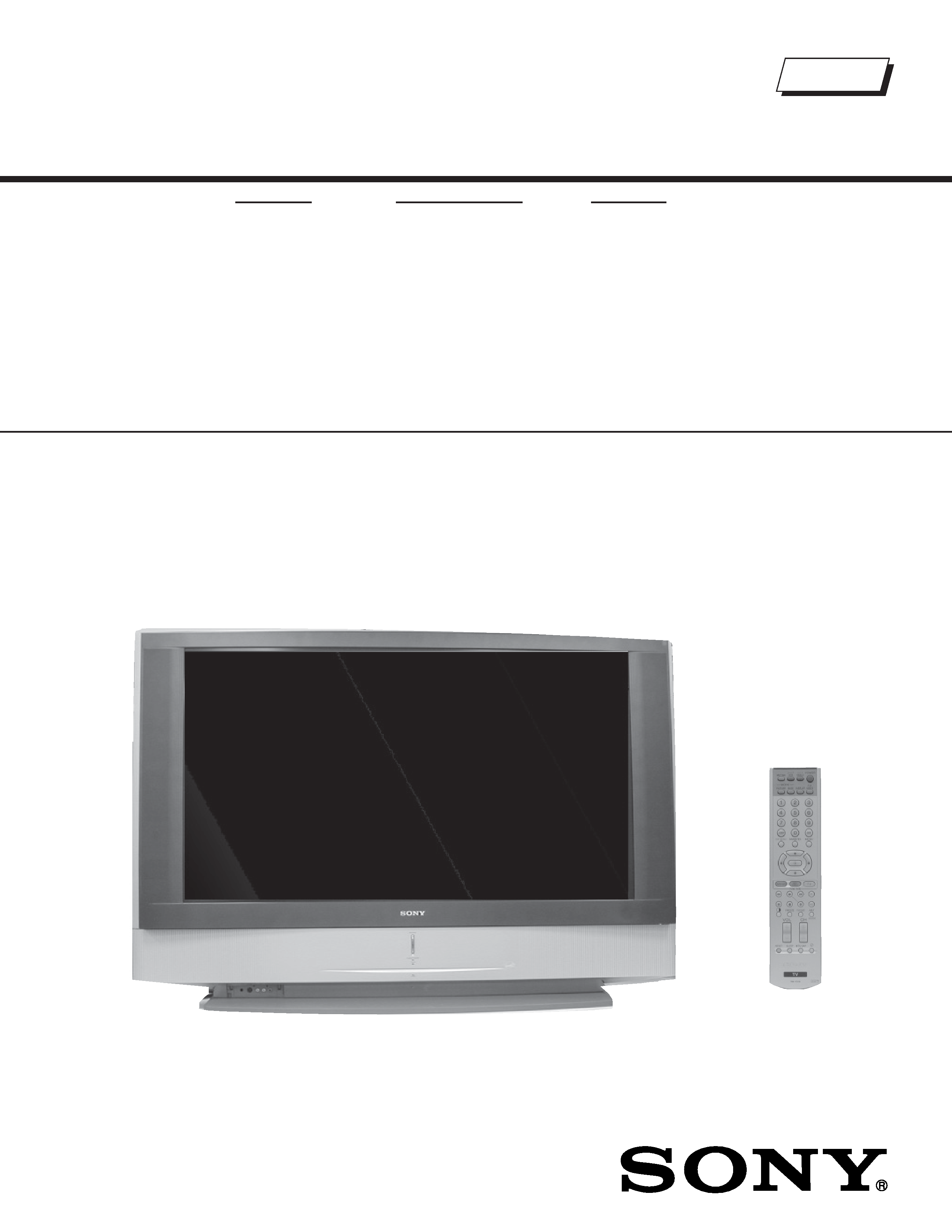
LCD PROJECTION TELEVISION
SERVICE MANUAL
LA-2 CHASSIS
MODEL NAME
REMOTE COMMANDER
DESTINATION
9-965-969-04
KF-42WE620
RM-Y916
US/CND/MEXICO
KF-50WE620
RM-Y916
US/CND/MEXICO
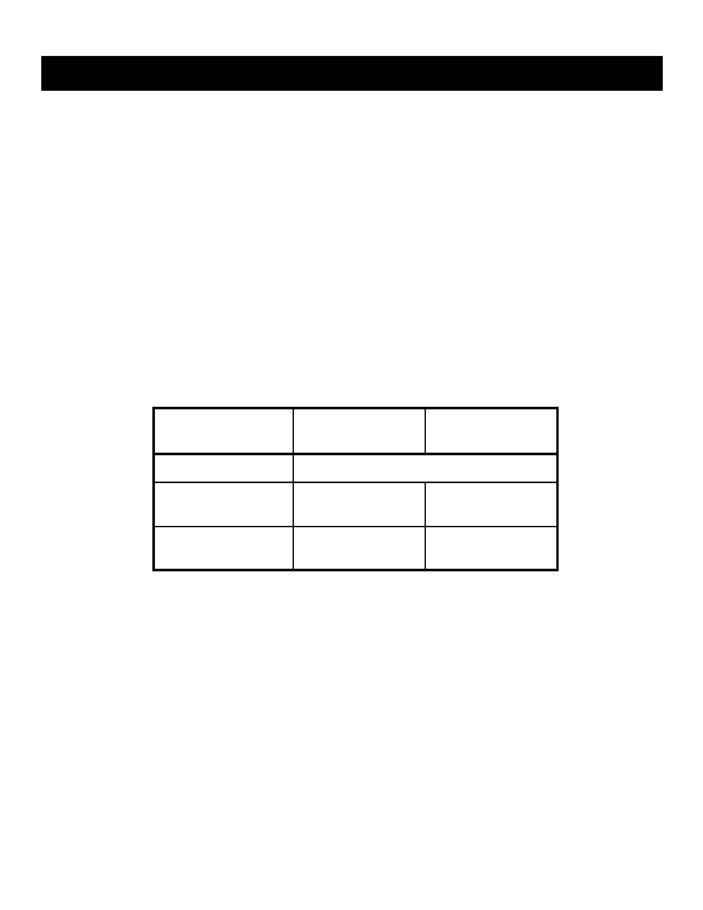
HISTORY INFORMATION FOR THE FOLLOWING MANUAL:
ORIGINAL MANUAL ISSUE DATE: 7/2004
:UPDATED ITEM
REVISION DATE
SUBJECT
7/2004
No revisions or updates are applicable at this time.
11/2004
Added new assembly part numbers to replace Screen Mirror Block Assy, Updated line art drawing
(Replaced Pg. 131 with Pg. 131)
Corrected line art drawing to show T Board, Added/Updated mechanical parts to exploded view section
Corrected page header (Replaced Pgs. 132 -135 with Pgs. 132 -135 )
Added/Updated Miscellaneous parts list (Replaced Pg. 159 with Pg. 159)
12/2004
Added Power Button Bracket part to Exploded View section (Replaced Pg. 131 with Pg. 131)
1/2005
Added Caution statement (Replaced Page 5 with Page 5)
LCD PROJECTION TELEVISION
SERVICE MANUAL
LA-2 CHASSIS
MODEL NAME
REMOTE COMMANDER
DESTINATION
9-965-969-04
KF-42WE620
RM-Y916
US/CND/MEXICO
KF-50WE620
RM-Y916
US/CND/MEXICO
Self Diagnosis
Supported model
KF-50WE620
RM-Y916

3
KF-42WE620/50WE620
KF-42WE620/50WE620
TABLE OF CONTENTS
Specifications ................................................................................. 4
Warnings and Cautions .................................................................. 5
Safety Check-Out ........................................................................... 6
Self-Diagnostic Function................................................................. 7
SECTION 1: DISASSEMBLY............................................................... 10
1-1. Rear Cover Removal............................................................ 10
1-2. Center Pillar Removal .......................................................... 10
1-3. Service Position ...................................................................11
1-4. Chassis Assembly and D.C. Fan Removal ...........................11
1-5. Power Supply Block Removal (Lamp Drive Unit)................. 12
1-6. UD Board and RF Antenna Switch Removal........................ 12
1-7. U Board Removal................................................................. 13
1-8. F and G1 Board Removal .................................................... 13
1-9. DIC Block, AU Board and C2 Board Removal ..................... 14
1-10.A Board Removal ................................................................. 14
1-11. T Board Removal ................................................................. 15
1-12.Front Cover Assembly Removal........................................... 15
1-12-1. Replacing the Lamp................................................. 15
1-13.H3 Board Removal (KF-42WE620 Only) ............................. 16
1-14.H4 Board Removal (KF-42WE610 Only) ............................. 16
1-15.H3 and H4 Board Removal (KF-50WE620 Only)................. 17
1-16.H2 Board Removal............................................................... 17
1-17.H1 Board Removal............................................................... 18
1-18.Screen Mirror Block Assembly Removal .............................. 18
SECTION 2: CIRCUIT ADJUSTMENTS.............................................. 19
2-1. Setting the Service Adjustment Mode .................................. 19
2-2. Service Adjustment Mode Memory ...................................... 19
2-3. Memory Write Confirmation Method .................................... 20
2-4. Remote Adjustment Buttons and Indicators ......................... 20
2-5. Service Data......................................................................... 21
2-6. ID Map Table ........................................................................ 93
SECTION 3: DIAGRAMS..................................................................... 94
3-1. Circuit Boards Location ........................................................ 94
3-2. Printed Wiring Boards and
Schematic Diagrams Information ......................................... 94
3-3. Block Diagrams .................................................................... 96
A Block Diagram (1 of 2) ................................................. 96
A Block Diagram (2 of 2) ................................................. 97
AU Block Diagram ........................................................... 98
G1 Block Diagram ........................................................... 99
H3, H1, H2, and T Block Diagrams ............................... 100
U Block Diagram ........................................................... 101
3-4. Schematics and Supporting Information ............................ 102
A Board Schematic Diagram (1 of 4).................................. 102
A Board Schematic Diagram (2 of 4).................................. 103
A Board Schematic Diagram (3 of 4).................................. 104
A Board Schematic Diagram (4 of 4).................................. 105
AU Board Schematic Diagram (1 of 2)............................... 108
AU Board Schematic Diagram (2 of 2)............................... 109
G1 Board Schematic Diagram ............................................ 111
F Board Schematic Diagram ...............................................112
U Board Schematic Diagram (1 of 3) ..................................115
U Board Schematic Diagram (2 of 3) ..................................116
U Board Schematic Diagram (3 of 3) ..................................117
UD Board Schematic Diagram (1 of 2)................................119
UD Board Schematic Diagram (2 of 2)............................... 120
H1 Board Schematic Diagram............................................ 122
H2 Board Schematic Diagram............................................ 124
H3 Board Schematic Diagram............................................ 126
H4 Board Schematic Diagram............................................ 128
T Board Schematic Diagram .............................................. 129
3-5. Semiconductors ................................................................. 130
SECTION 4: EXPLODED VIEWS ...................................................... 131
4-1. Cover, Screen Mirror Block ................................................ 131
4-2. Bottom Block ...................................................................... 132
4-3. Chassis - 1 ......................................................................... 133
4-4. Chassis - 2 ......................................................................... 134
4-5. Optical Unit Block............................................................... 135
SECTION 5: ELECTRICAL PARTS LIST.......................................... 136
SECTION TITLE
PAGE
SECTION TITLE
PAGE
4
KF-42WE620/50WE620
KF-42WE620/50WE620
SPECIFICATIONS
Design and specifications are subject to change without notice.
120V AC, 60Hz
210W
Under 1 W
DVI-HDTV
1 terminal, 3.3V T.M.D.S., 50 ohms
The DVI-HDTV input terminal is compliant with the EIA-861
standard and is not intended for use with personal computers.
Video (IN)
4 total
1Vp-p, 75ohms unbalanced, sync negative
S Video (IN)
4 total
Y: 1Vp-p, 75ohms unbalanced, sync negative
C: 0.286Vp-p (Burst signal), 75ohms
Audio (IN)
6 total
500 mVrms (100% modulation)
Impedance:47 kilo ohms
Power Requirements
Power Consumption (W)
In Use (Max)
In Standby
Inputs/Outputs
Audio (VAR/FIX)
1 total
500 mVrms at the maximum volume setting (Variable)
500 mVrms (Fixed)
Impedance (Output):2 kilo ohm
Control S (IN/OUT)
1 total
Minijacks
Component Video Input
2 (Y, PB, PR)
Y: 1.0 Vp-p, 75 ohms unbalanced, sync negative
PB: 0.7 Vp-p, 75 ohms;
PR: 0.7 Vp-p, 75 ohms
RF Inputs
2 total
Converter
1 total
KF-42WE620
KF-50WE620
Speaker Output (W)
Woofer
Dimensions (W x H x D)
mm
1,201 x 819 x 371 mm
1,377 x 928 x 452 mm
in
47
1/4 x 32 1/4 x 14 1/2 in
54
1/4 x 36 1/2 x 17 3/4 in
Mass
kg
32 kg
39.5 kg
lbs
70 lbs 12 oz
87 lbs 1 oz
5W x 2
20W
Television system
American TV standard, NTSC
Channel coverage
VHF: 2-13/ UHF: 14-69/ CATV: 1-125
Antenna
75-ohm external antenna terminal for VHF/UHF
Projection System
3 LCD Panels, 1 lens projection system
LCD Panel
0.87 inch TFT LCD panel Approx. 3.28 million dots (1,092,168
pixels)
Projection Lens
High Performance, large diameter hybrid lens F2.4
Lamp
UHP lamp, 100W
XL-2100U
Supplied Accessories
Remote Commander RM-Y916
Two Size AA (R6) Batteries
Cleaning Cloth
Optional Accessories
TV Stand
SU-GW2 (KF-42WE620 Only)
SU-GW1 (KF-50WE620 Only)
Lamp
XL-2100U
Control S Cable
RK-G69
Component Video Cable
VMC-10/30
AV Receiver
STR series or equivalent

5
KF-42WE620/50WE620
KF-42WE620/50WE620
WARNINGS AND CAUTIONS
CAUTION
These servicing instructions are for use by qualified service personnel only. To reduce the risk of electric shock, do not perform any
servicing other than that contained in the operating instructions unless you are qualified to do so.
WARNING!!
An isolation transformer should be used during any service to avoid possible shock hazard, because of live chassis. The chassis of
this receiver is directly connected to the ac power line.
! SAFETY-RELATED COMPONENT WARNING!!
Components identified by shading and ! mark on the schematic diagrams, exploded views, and in the parts list are critical for safe
operation. Replace these components with Sony parts whose part numbers appear as shown in this manual or in supplements
published by Sony. Circuit adjustments that are critical for safe operation are identified in this manual. Follow these procedures
whenever critical components are replaced or improper operation is suspected.
ATTENTION!!
Ces instructions de service sont à l'usage du personnel de service qualifié seulement. Pour prévenir le risque de choc électrique, ne
pas faire l'entretien autre que celui contenu dans le Mode d'emploi à moins que vous soyez qualifié faire ainsi.
Afin d'eviter tout risque d'electrocution provenant d'un chássis sous tension, un transformateur d'isolement doit etre utilisé lors de tout
dépannage. Le chássis de ce récepteur est directement raccordé à l'alimentation du secteur.
! ATTENTION AUX COMPOSANTS RELATIFS A LA SECURITE!!
Les composants identifies par une trame et par une marque ! sur les schemas de principe, les vues explosees et les listes de pieces
sont d'une importance critique pour la securite du fonctionnement. Ne les remplacer que par des composants Sony dont le numero
de piece est indique dans le present manuel ou dans des supplements publies par Sony. Les reglages de circuit dont l'importance
est critique pour la securite du fonctionnement sont identifies dans le present manuel. Suivre ces procedures lors de chaque
remplacement de composants critiques, ou lorsqu'un mauvais fonctionnement suspecte.